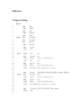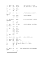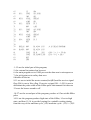
1
14
machine cycle * 5 = 12us.14
17-20 are the program produce low state of the 40khz, the method as use
as 14-16, two of them will add to the full cycle = 12us +12us = 24us,
nearly to the 40khz, 1/25us = 40khz, 1/24us = 38khz, because that the
40khz = 1/25us/2 = 12.5us(half on/off cycle) in 12Mhz clock, the
machine cycle = 1us, the IC can’t provide less than 1us clock.
So 38khz is the best resolution to this situation.
21 is use the looping provide 0.3ms timing 24us * 6 times * 2machine
cycle(2us) = 0.3ms
22-27 is use to do the looping to prevent the cross talk of the two sensor
because the transmits will need two time so the looping will use 0.6ms
29-38,42-61 is the receiver program
29, 30 is use to setup the Int0 and enable the trigger, 32 R7 is use to limit
the detect range(10feet+/-1feet)
33 & 34 is use observe that the detect range has been out now.
35 is use to call 1 feet time counter delay to counter feet.
38 is use to disable the input signal after the counting feet.
42-52is a Int0 service routine,
42 is use to set the flag(R6) to Ack. the main program that is the signal is
receive.
45-52 is use to feet counter to generate the sound, when the less feet has
been count, the sound will be generate more frequently. There is about 0.1
second generate in every period.
54-61 is a delay program to counter the 1 feet ultrasound transmits in the
air the ultrasound transmits has been cal to 1836us.
39-40,63-84 is the sound generate program
39-40 is use to call the sound program to generate system normal “beep”
sound(no detect)
63-84 is the procedure that generate single beep sound.
63 is use to enable the sound
64-84 is the procedure that make a 0.5s delay.
14