1
Mercury Four & Six Cylinder (1955-1965)
OLD OUTBOARD MOTOR
MERCURY FOUR & SIX CYLINDER
(1955-1965)
MODELS
FOUR CYLINDER MODELS
Y«ar Produced
1955
1956
1957
1958
1959
1960
1961
1962
1963
1964
1965
Mk 55
Mk 55. 55H
Mk 55, 55H
Mk 55, 55H
Mk 35A
Merc 300
Merc 350
Mk 30V 30H
Mk 30, 30H
Mk 30. 30H
Mk 58
Mk 55A. 58A
Merc 400
Merc 400, 500
Merc 450, 500
Merc 500
Merc 500
Merc 500
Merc 650
Merc 650
Merc 650
40 • 50
5500 - 5800
65
5200
2A
27/t
2.3
CONDENSED SERVICE DATA
TXJNE-UP
Rated Horsepower
Rated rpm
Bore—Inches
Stroke—Inches
Displacement—Cu. In
Firing Order
Compression (a^ Cranking Speed
30
5400
2 7/64
2 Ve
29.78
35-40
5500 - 5800
21/e
39.6
2^8
44
1-3-2-4
60
- Not more than 15 psi variation between cylinders
Spark Plug
Champion
AC
Electrode gap
IGNITION SYSTEM
Make
Point gap
Carburetor
Make
jgj
M44C
0.025
Fuel—Oil Ratio
161
I6J
M44C
0.025
M44C
0.025
HI
0.025
-Kiekhaeler or FM
0.008 - 0.010
0.008-0.010
Kiekhaefer
0.008-0.010
Kiekhaefer
0.008-0.010
TUlotson
TiUotson
TiUotson
See Text
See Text
20:1
TiUotson
or Carter
20:1
SIZES—CLEARANCES
Piston Rings
End gap
Side clearance
Publication Not Authorized by Manufacturer
Piston Skirt Clearance.
Crankshaft Bearing Type—
Top main bearing
Intermediate main bearings
Center main bearing
No. used
Bottom Main Bearing
Crankpin
No. each rod
Piston Pin Bearing
No. used, each
tSome early models use 56 rollers
Ball Bearing
Bushing
Roller
56
Ball Bearing
Roller
25
Roller
22
BaU Bearing
Bushing
RoUer
56
BaU Bearing
RoUer
25
Roller
22
BaU Bearing
Bushing
RoUer
28t
BaU Bearing
RoUer
25
RoUer
22
TIGHTENING TORQUES
(AU Values In Inch-Pounds Unless Noted)
Connecting Rod
180
Flywheel Nut—
70 hp and below.
65 Ft.-Lbs.
80 hp and up
85 Ft.-Lbs.
Reed Valves
35-40
Crankcase Screws
150
Cylinder Cover
.60
Exhaust Cover
60
Intake Manifold
45-60
Spark Plug
240
102
BaU Bearing
Bushing
RoUer
56
BoU Bearing
RoUer
32
RoUer
29
i
SERVICE MANUAL
Mercury Four & Six Cylinder (1955-1965)
MERCURY FOUR & SIX CYLINDER
(1955-1965)
MODELS
SIX CYLINDER MODELS
Year Produced
1957
1958
1959
1960
1961
1962
1963
1964
1965
Mk75E
Mk75E
Mk78E
Mk75A, 78A
Merc 600, 700
Merc 600, 700
Merc 800
Merc 800
Merc 850
Merc 1000
Merc 850. 1000
Merc 850. 1000
Merc 900. 1000
CONDENSED SERVICE DATA
TUNE-UP
Rated Horsepower
Rated rpm
Bore—Inches
Stroke—Inches
Displacement—Cu. In
Firing Order
Compression @ Cranking Speed
Spark Plug
Champion
AC
Electrode g a p
Distributor
Make
Point g a p
Carburetor
Make
Fuel—Oil Ratio
60
60-70
80-85
85-100
5500
5500
5200
5200
2^
2^
2V4
1V%
IWt
2Vi
2»/8
2.3
59.4
66
76
90
1-6-4-2-5-3
1-4-5-2-3-6
Not more than 15 psi variation
between cylinders
I6J
J6J
I4J
JiJ
0.025
0.025
0.025
0.025
Own
90" DweU
Own
90*^ DweU
Own
90" Dwell
Own
90° Dwell
TiUotson
20:1
TiUotson
20:1
TiUotson
20:1
TUlotson
See Text
SIZES—CLEARANCES
Piston
End
Side
Piston
Rings
gap
clearance
Skirt Clearance.
Crankshaft Bearing Type —
Top Main Bearing
Main Bearing (2, 4 & 6)
Main Bearing (3 & 5)
No. Used Each
Bottom Main Bearing
Crankpin
No. Each Rod
Piston Pin Bearing
No. used, each
Publication Not Authorized by Manufacturer
BaU Bearing
RoUer
56
BaU Bearing
RoUer
25
RoUer
22
BaU Bearing
BaU Bearing
Bushing with Reed Valve
RoUer
RoUer
56
56
BaU Bearing
BaU Bearing
RoUer
RoUer
25
30
RoUer
RoUer
22
25
BaU Bearing
RoUer
56
BaU Bearing
RoUer
30
RoUer
25
TIGHTENING TORQUES
{AU Values In Inch-Pounds Unless Noted)
Connecting Rod
180
Flywheel Nut —
70 hp and below
65 Ft.-Lbs.
80 hp and up
..85 Ft.-lbs.
Reed Valves
35-40
Crankcase Screws
150
Cylinder Cover
60
Ebchaust Cover
60
Intake Manifold
45-60
Spark Phig
...240
103
Mercury Four & Six Cylinder (1955-1965)
OLD OUTBOARD MOTOR
LUBRICATION
The power head is lubricated by oil
mixed with the fuel. For motors with "Quicksilver" lower units, one 12 ounce can of
"Formula 2 Quicksilver" 2-cycle engine oil
should be mixed with each gallon of gasoline. Other oils and fuel oil ratios are not
recommended for these motors.
For motors except those with "Quicksilver" lower unit, observe the foUowing.
If "Formula 2 Quicksilver" two-cycle engine oil is used, one 12 ounch can should
bo mixed with each 2 gallons of gasoline.
If "Formula SO Quicksilver" oil is used on
1963 and later motors, one 12 ounce can
should be mixed with each 5 gallons of
gasoline. If "Quicksilver" oil is not available, a good grade, non-detergent, SAE
30 motor oil may be substituted by increasing oil ratio to y2-pint oU with each gallone of gasoline (1:16 ratio).
Tho lower unit gears and bearings are
lubricated by oil contained in the gear case.
Only "EXTRA-DUTY Quicksilver Outboard
Gear Lubricant" should be used. Gearcase is fiUed through the filler hole until
lubricant reaches the level of the vent hole.
NOTE: On most models, the plugs are located on port side of gearcase. If both
plugs are the same height, the forward
plug is the fiUer hole. If one plug is above
the other, the LOWER plug is the fiUer
h ole. Lubricant should be maintained at
level of vent plug.
1 4
5 6
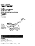
Fig. M7-1—Exploded view
of Carter corburefor used
on some Mork 55H models.
1.
2.
3.
4.
5.
6.
7.
8.
9.
10.
11.
12.
13.
H.
15.
16.
17.
Throttle shaft
Spring
Throttle valve
Body
Spring
Idle needle
Choke detent
Choke valve
Choke shaft
Inlet needle & seat
Main nozzle
Float shaft
Spring
Float
Gasket
High speed needle
Cap screw
throttle while tightening screws. Always
use new screws to secure the valve.
TUlotson Carburetors: Fig. M7-2 shows an
exploded view of carburetor typical of that
used on aU models. Minor difference wiU be
FUEL SYSTEM
apparent upon examination. AI-49A carCARBURETOR. TiUotson carburetors are buretors used on some early models do not
used on all models except some Mark 55H use the fuel filter (1 through 4). Some early
motors, which use Carter Type N carbure- carburetors employ an adjustable high speed
tors. Two carburetors are used on four cyl- needle instead of the fixed jet (17).
inder motors; three carburetors on six cylInitial setting for carburetors equipped
inder models. Refer to the appropriate following paragraphs for overhaul and adjust- with the high speed adjustment needle is
one tum open from closed position for the
ment procedures.
idle needle (16); and 1^2 turns open for the
Carter Model N-2537S: Refer to Fig. M7-1. high speed adjustment needle (which reInitial setting is IVA turns open for both the places the high speed jet 17). Run motor
idle adjusting needle (6) and high speed until operating temperature is reached, then
adjusting needle (16). Final adjustment shift to forward gear and open the throtUe.
must be made under load after operating Slowly turn the high speed adjustment
temperature has been reached. Adjust the needle clockwise untU engine misses, then
high-speed needle to provide the leanest back needle out approximately 1^2-turn. Adsetting which wiU permit full power and just the high speed needle for aU carbureacceleration. Adjust the idle needle after tors in the same manner, for equal perhigh speed needle has been adjusted, to formance. After high speed needles have
provide smooth operation under load at been properly adjusted, regulate the idle
slow speeds. Clockwise rotation of the high adjustment needles (18) for aU carburetors
speed adjusting needle leans the mixture. untU engine runs smoothly under load at
Clockwise rotation of the idle needle pro- slow speed. Turning idle mixture needle
vides a richer mixture.
clockwise wiU lean the mixture.
To disassemble the carburetor, scribe a
On carburetors employing the fixed main
line on the body and bowl to assure proper jet, high speed mixture adjustment may be
assembly, then remove the bowl nut and made for special conditions by changing
fuel bowl. To check and adjust the float the size of jet (17). The standard jet should
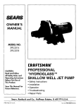
Fig. M7-2—Exploded view of Ttllotson carlevel, invert the carburetor body with bowl normaUy be used. If motor is operated at
buretor of tKe general type used on most
removed, and measure the clearance be- altitudes above 2500 feet, performance can
models.
tween nearest edge of float and gasket usuaUy be improved by instaUing a smaller
11. Throttle lever
Strainer
cover
surface of body flange. This clearance jet. Be sure the same size jet is used in all
12. Throttle shaft
Gasket
should be 11/64-inch with inlet needle carburetors on the motor.
13. Idle tube
Strainer
14. Throttle valve
Gasket
seated. Adjust by bending Up of float.
15. Body
Bowl cover
On carburetors employing the fixed main
lG. Idle needle
Inlet
needle
&
seat
When instaUing throttle valve (3). make jet. initial setting for the idle adjustment
IT. High speed Je'
Shaft
sure the "C" trademark is toward idle port. needle (16) is one tum open from the closed
18. Main nozzle
Secondary lever
19. Spring
Primary lever
Center throttle valve by completely closing position. Idle needle must be adjusted under
10. Float
19
104
(
SERVICE MANUAL
Mercury Four & Six Cylinder (1955-1965)
Fig. M7-4 — Corburetor
connecting linkage used
on six cylinder models.
Four cylinder models are
similar.
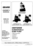
Ffg. M7-3—Schemotic view of float mecKonfsm showing points of adjustment. Refer
to text.
A. Closing adjustment
B. Open adjustment
G. Inlet needle
I
8. Secondary lever
9. Primar>' iever
10. Float
load to obtain smooth operation at
speeds. Turning needle clockwise wiU lean
the mixture.
The recommended fuel level is approximately f^-inch below gasket surface of
float bowl. To adjust the float, remove bowl
cover (5) and refer to Fig. M7-3. Invert the
cover and. with inlet needle (6) closed.
measure the distance between primary
lever (9) and gasket surface of bowl cover
as shown at (A). This distance should be
Jl-inch; if it is not, bend the curved tang
on secondary lever (8) untU correct measurement is obtained. After adjustment is made,
bend the vertical tang on primary lever (9)
to allow a maximum clearance (B) of 0.040,
between the secondary lever (8) and inlet
needle (6), The contact spring located in
center of float should extend 5/64-inch
above top of float (10). Check to see that
spring has not been stretched or damaged.
Standard main jet size (diameter) for carburetors with fixed type main jet (17—Fig.
M7-2) are as follows:
Model A7-54A
Main jet
0.055
Model AJ-55A
Main jet
0.055
Model KA.2A
Main jet
0.063
Model KA-7A
Main jet
0.081
Model ICA.8A
Main jet
0.061
Model KA-9A
Main jet
0.061
Model KA-lOA
Main jet
0.065
Model KA-UA
Main jet
0.065
Model KA-12A
Main jet
0.061
1.
2.
3.
4.
5.
6.
7.
8.
9.
10.
Choke solenoid
Plunger
Choke button
Link
Choke rod
Choke valve
Carburetor
Cluster lever
Clamp
Pickup bracket
Model KA-13A
Main jet
0.059
Model KA-14A
Main jet
0.069
Modal KA-IBA
Main jet
0.069
Model KA-17A
Main jet
0.059
Model KA-18A
Main jet
0.059
M>del KA-19A
Main jet
0.059
Model KB-2A
Main jet
0.055
Model KB-3A
Main jet
0.057
Model KC-IA
Main jet
0.071
Model KC-2A
Main jet
0.071
Model KC-3A
Main jet
0.055
Model KC-5A
Main jet
0.069
Model KC-6A
Main jet
0.049
Model KC-7A
Main jet
0.065
SPEED CONTROL LINKAGE. The speed
control lever is directly attached to the
magneto or distributor to advance or retard
the ignition timing. The throttle valve is
synchronized to open as the timing is advanced. It is extremely important that ignition timing and throttle valve opening be
correctly synchronized to obtain satisfactory
operation. When synchronizing the speed
control linkage, first adjust the timing as
ouUined in the IGNITION section; then proceed as outlined in the appropriate foUowing paragraphs:
Fig. M7-5—Speed control mechanism used
on Mark 30 & 55 series. Refer to text for
details.
1. Actuating bracket
2. Throttle pickup
3. Follower roller
105
OLD OUTBOARD MOTOR
Mercury Four & Six Cylinder (1955-1965)
A
3
Fig. M7-6—Throttle control mechanism used
on late four cylinder models.
1.
2.
3.
4.
A.
Cluster finger
Pickup pin
Adjusting cap screw
F\in throttle stop screw
Adjustment clearance
Fig. M7-8—Cluster lever (3) must be adjusted on throttle shaft on some early
models. Refer to text.
A.
S.
3.
5.
Clearance
Set screw
Cluster finger
No. 1 pickup pin
Fig. M7-T0—Reverse throttle pickup adjustment used on older models.
1. Reverse lever
2. Reverse pickup finger
Fig. M7-9—Latch spring adjustment is required on some early models.
Fig. M7-7—Throttle control mechanism used
on early six cylinder models.
A. Adjusting screw
L. Latch
P. Sector pin
shown in Fig. M7-9. Hold the speed coitrol
sector and move the distributor body ounter-clockwise toward the advance stop. Note
the clearance between latch spring (L) and
sector pin (P) while torque is appUed. The
spring should latch over the pin with no
more than 1/64-inch clearance between pin
and latch spring. Adjust by loosening the
screws retaining latch (L) to distribvitor.
After the adjustment is made, move control
lever untU distributor advance stop contacts
the crankcase; then adjust the screw (A)
untU latch (L) is unhooked from pin (P).
Synchronize the reverse throttle mechanism with motor in operation a& foUf»ws:
attaching screws. Move the speed control
Loosen the screws which retain the reverse
lever to 'Tast" position and adjust the fuU throttle lever (1 Fig. M7-10) to the sector
throttle stop screw (4) to aUow throttle levei
cjear and move the lever as far as possible
(1) 1/64-inch travel to full open throttle
Gway from throttle reverse pickup (2). Adposition.
vance the distributor in the "Reverse' diMark 30 and 55 Series: Make certain
Move speed control lever fuUy to "Slow"
rection until engine speed is 1000 pm.
that magneto is properly timed and adposition and adjust the idle limiter screw
Move the lever (1) untU it just touches rejusted; then adjust carburetor to obtain a
(opposite full throttle stop screw 4) untU the verse pickup (2) and tighten the 8cr*>WB.
smooth idle speed of 600 rpm. Loosen the
recommended slow idle speed of 525 rpm Limit the maximum reverse speed to iOOO
cap screws retaining the actuating bracket
is obtained.
rpm or less by moving the lever stof on
(.1—Fig. M7-5) to magneto frame and slide
th© foUower roUer (3) crway from throttle
Mark 75. 75A. 78 and 78A: First make the lower cowl.
pick-up (2). With motor at operating temcertain that the distributor is properly timed
Merc 600, 700 and 800 Direct Reverfting:
perature, shift to forward gear and move
and adjusted. On Mark 75 and 75A, fuUy
the speed control lever until engine speed
retard the throttle and, with throtUe valve First make certain that distributor is f roperly timed and adjusted. To synchrcnize
increases to 1000-1100 rpm for Mark 30, 30E.
closed, loosen the set screw (S—Fig. M7-8)
the forward throttle refer to Fig. M7-11. A^ith
30H or Mark 55H with TUlotson carburetor;
in throttle valve cluster (3). Move the clusthe engine not running, move the s})eed
1100-1200 rpm for Mark 55 and 55E; or
ter (3) on throttle valve shaft untU a clearcontrol lever until distributor pilot just
2000-2400 rpm for Mark 55H vrith Cccrter
ance (A) of ^-inch exists between pickup
touches the maximum advance stop screw.
carburetor. With engine speeds as indicated,
finger and No. 1 pickup pin (5). On later
Loosen the screws (S) attaching pickup >>late
move actuating bracket (1) until foUower
motors, the cluster is automaticaUy posi(2) to the sector gear and move the >)late
roUer (3) just touches throttle pick-up arm
tioned by the set screw.
until the nylon covered pickup pin (i) is
(2); then tighten the retaining screws.
On aU models, slowly move the speed
not touching the cluster finger (6); then
Other Four-Cylinder Models: First make
control lever in the "forward" position (enbend pickup tab (3) in or out untU a No. 48
certain that magneto is properly timed and
gine not running) untU the magneto advance
twist driU (0.076 gage) can just be ins^»rted
adjusted. With the engine not running,
stop just touches the crankcase. Refer to
between port side of throttle valve and carslowly move the speed control lever toward
Fig. M7-7. Loosen the screws securing the
buretor barrel as shown at (D\ Remove the
Ihe "Fast" position until magneto advance
throttle actuator assembly (1) to sector gear;
drill or gage. Move the speed control fever
stop just touches the crankcase. Hefer to
then move the plate until -j^-inch clearance
to retard the ignition until spark occurs at
Fig. M7-6. Loosen the screws (3) securing
exists between pickup finger (4) and pickup
0.030 (inches) before TDC of piston.
the throttle actuator assembly to economizer
pin (2). Secure advance plate in this position.
collar; then move the actuator plate until
NOTE: This inteTmediate timing advance
On older models, move the speed control
0.015 clearance (A) exUts between foUower lever slightly toward "Slow" position and
position can be determined using Meicury
(2) and throttle cluster lever (1). Tighten tht
Timing Gage 91-31161 Al for gear shift
check the adjustment of the latch spring a&
1.
2.
3.
4.
5.
106
Actuator assembly
Pickup pin
Cluster lever
Pickup finger
No. 1 pickup pin
i
SERVICE MANUAL
Mercury Four & Six Cylinder (1955-1965)
Fig. M7-12—Reverse pickup finger adjustment used on some models. Refer to text.
' »r
Fig. M7-11—Forward throttle control mechanism used on late models. Refer to text for
method of adjustment.
1.
2.
3.
4.
I
Cluster lever
Pickup plate
Pickup tab
Pickup finger
'>. Pickup pin
t'». Pickup finger
D. Drill (gage)
S. Attaching screw
models: or 91-30290Al for direct reversing
models. Thread timing gage into No, 4 (from
top) spark plug hole on Merc 600 or 700
models: or No. 3 spark plug hole ior Merc
800 models. Make sure that center plunger
of gage fits into notches of threaded outer
body. Turn flywheel until the piston strikes
gage: then thread gage out until crankpin
will pass over center while in contact with
gage plunger. Rotate flywheel counterclockwise: then without moving threaded
outer gage body, depress center plunger
and turn plunger Vi-turn. Rotate flywheel
ciocJcwise until piston crown strikes the
plunger. Attach one lead of a timing test
light to the No. 1 Coil Primary (White) Lead
of Terminai Block, and ground the other
test lead. Retard the distributor (clockwise)
until test bulb lights: then move to the advance direction (counter-clockwise) until test
bulb just goes out.
With intermediate timing position determined, move pickup plate (2—Fig. M7-U)
until tab (3) just touches the cluster finger
(4) and tighten the attaching screws. Again
move the speed control lever untU distributor pUot just touches the maximum advance
stop screw; then bend the nylon covered
pickup pin (5) untU 0.000-0.015 clearance
exists between pickup finger (5) and cluster
finger (6).
To synchronize the reverse throttle, proceed as follows:
On Merc 600 and 700. make sure that
throttle valves are closed; then loosen
clamp screw (1—Fig. M-712) and position reverse pickup finger (2) so that leading edge
is approximately ^e-inch in front of carburetor float bowl as shown. Loosen the
screws attaching the reverse pickup stop to
the distributor sector gvXir and adjust tho
reverse timing untU points break at 0.030
(inches) before Top Dead Center of the
piston.
1. Clamp screw
2. Reverse pickup finger
Fig. M7-14 — With distributor in intermediate advance position, loosen screws (S)
and reposition pickup plate (2) until tab
(3) just touches cluster finger ( 4 ) .
1.
2.
3.
4.
5.
6.
S.
Carburetor cluster
Pickup plate
Pickup tab
Cluster finger
Pickup pin
Cluster finger
Cap screws
Merc 700. 800, 850, 1000, FuU Gear Shift:
Firs! make sure that distributor is properly
timod and adjusted. Correct synchronization requires that an intermediate timing
advance position of 0.015 (inches for piston
crown before TDC) be determined. This is
most conveniently done by using the special Mercury Timing Gage (Part No. 9131161A1) and a continuity timing light.
Fig. H7-13—Reverse throttle pickup adjustMake sure center plunger of gage is seated
ment used on Merc 800.
in notches of threaded outer case and
thread the gage into No. 4 spark plug
1. Pickup stop
2. Pickup finder
hole for Merc 700; or No. 3 spark plug
3. Drill (gage)
hole for other modeb. Turn flywheel until
the respective piston is in approximately
NOTE: Proceed as previously outlined ior Top Dead Center position, then thread the
determirung intermediate advance: except gage in or out until crankshaft will rock
rotate flywheel clockwise from top dead
over TDC while piston crown is in contact
center, then counter-clockwise to the ad- with gage plunger. Rotate crankshaft
vance REVERSE position. Move distributor counter-clockwise; then, without moving
COUNTERCLOCKWISE until test bulb lights:threaded portion of gage, depress center
then CLOCKWISE to the timing position. plunger and turn plunger V4 turn. Rotate
When intermediate timing position has flywheel clockwise until piston crown strikes
been determined, move the reverse pickup the plunger. Attach one lead of timing test
light to the No. 1 CoU Primary (White) lead
stop to just contact reverse finger (2) and
cf Terminal Block, and ground the other test
tighten the attaching screws.
On Merc 800 direct reversing motors refer lead. Retard the distributor (clockwise) until
to Fig. M7-13. The reverse pickup lever (1) test bulb lights; then move in the advance
should be moved to the end of slot away direction until test bulb just goes out.
Refer to Fig. M7-14. With distributor in
from pickup finger (2) and the retaining
screw tightened and safety wired. If cor- previously established intermediate advance
rectly adjusted, this lever should not be position, loosen the cap screws (S) securing
moved. Move the speed control lever to- pickup plate (2) to distributor body, and
ward "Fast" (reverse) direction until dis- move the plate untU the tab (3) just touches
tributor contacts the maximum (reverse) the cluster finger (4). Tighten the cap screws.
stop. Loosen the screw which clamps the Move the control lever to advance timing
reverse pickup lever to throttle shaft. Man- until the maximum timing advance screw
uaUy open the carburetor throttle untU a just touches distributor body and bend the
No. 40 (0.098) driU bit can be inserted be- nylon covered pickup pin (5) until a cleartween throttle valve and port side of car- ance of 0.0000 0.015 exists between pickup
buretor barrel as shown at '3). With driU pin and cluster finger (6).
bit holding throttle valve open, move the
Move the speed control lever fully to
pickup finger (2) on throttle shaft untU it
"Fast" position and adjust the full throttle
contacts pickup stop (1) and tighten the stop screw (2~Fig. M7-15) to aUow the
clamping screw. Remove the driU.
throttle shaft 1/64-inch travel to fuU open
107
Mercury Four & Six Cylinder (1955-1965)
OLD OUTBOARD MOTOR
Fig. M7-18 ~ Exploded
view of fuel pump and associated parts.
1.
2.
3.
4.
5.
6.
7.
8.
9.
10.
11.
12.
13.
Pump body
Valve gasket
Outlet check valve
Inlet check valve
Retainer
Gasket
Diaphragm
Gasket
Outlet hose
Inlet hose
Spring
Adapter valve
Adapter
Fig. M7-15—View of stop bracket showing
location of throttle stop screws.
1. ispark advance stop
2. Throttle stop
3. Idle stop
When overhauling the fuel pump, ise
position. Adjust the idle stop screw (3) to
Fig. M7-18 as a guide. All defective or quescbtain an idle speed of 500 rpm in forward
gear with motor at operating temperature. tionable parts should be renewed.
RS RP
Fig. M7-16 — Intermediate main bearing
showing inlet reed valves. Reed petals (RP)
are right and left hand units. When installing reed petals, place the reed with the
cut-out notch (N) on the left as shown.
Adfust free height of reed stop (RS).
REED VALVES. The inlet reed valves are
located on the crankshaft second and fourth
main bearing assembUes on four cylinder
models; and on the second, fourth and sixth
main bearings on six cylinder models. Each
reed valve unit suppUes fuel mixture from
one of the carburetors to the two adjoining
cylinders.
Reed petals (RP—Fig. M7-16) should be
perfecUy flat and have no more than 0.007
clearance between free end of reed petal
and seating surface of center main bearing.
The reed stop (RS) must be carefuUy adjusted to TiT-inch on Merc 650 and 1000;
and yiv.-inch on other models. This clearance is measured between end of stop
and seating surface of reed plate as
shown at (A). Seating surface of bearing must be smooth and flat, and may
be refinished on a lapping plate after removing reed stops, reed valves and dowels.
Do not attempt to bend or straighten a reed
petal to modify performance or to salvage
a damaged reed. Never instaU a bent reed.
Lubricate the reed valve units with "QuicksUver" Multipurpose Lubricant or a light
distributor cam grease when reassembling.
Each reed valve unit has eight reeds
which are right-hand and left-hand units,
and are avaUable only as a matched set.
When instaUing reed valves, place the reed
petal with the cut-out notch (N) to the left
as shown. Crankshaft must be removed before reed valve units can be serviced.
FUEL PUMP. Diaphragm type fuel pumps
are used. Two fuel pumps are used on six
cylinder models. Pressure and vacuum pulsations from the crankcases alternate to puU
fuel from the supply tank and supply the
carburetor. Most of the work is performed
by the main supply chamber (5—-Fig. M7-17).
Vacuum in the crankcase puUs the diaphragm (2) downward causing fuel to be
drawn through inlet line (8). past inlet
Fig. M7-T7—Schematic view of diaphragm
check valve (7) into main pump chamber (5).
type fuel pump. Pump body mounts on side
of cylinder block and is ported to two The alternate pressure forces diaphragm out
and fuel leaves the chamber through outlet
crankcases as shown. Six cylinder models
use fwo fuel pumps.
check valve (6). The booster pump chamber
(3) serves to dampen the action of the larger,
5. Main fuel chamber
1. Pressure ports
6. Outlet check valve
2. Dlaphra^i^m
main pump chamber (5), and increase the
7. Inlet check valve
3. Booster chamber
maximum potential fuel flow.
8. Fuel Inlet
4. To carburetor
108
IGNITION
Four cyUnder models use a belt driven
magneto. Six cylinder models use a belt
driven distributor. Refer to the appropnate
following paragraphs.
MAGNETO. Breaker point gap should be
set to provide 48 degrees dwell for all
models except MK30 and 55. DweU for
Mark 30 and 55 should be 54 degrees.
Breaker point gap wiU normaUy be O.')080.010. Dwell plate (part number C-91-3184A2)
is available for setting angle that breoker
points are closed. Breaker point spring ension should be 33-37 ounces, measvred
from curve of breaker arm next to rub! ing
block.
A quick test of magneto condition car. be
made by removing high tension wire from
one spark plug with engine running. S^'ark
should jump a ^^-inch gap at idle speed
To instaU the magneto drivo belt, remove
the flange plate on top of magneto pulley:
then remove the flywheel using a puUer.
Tum the magneto puUey untU the arrow
cast into top of pulley points toward crmkshaft as shown in Fig. M7-20. When instillation is complete, flywheel and magneto timing marks must be toward each other and
on the axis of a line connecting the crankshaft and magneto shaft as shown at (TM).
The magneto shaft has a blind spline wliich
aligns with a simUar spline in magneto
pulley shaft.
DISTRIBUTOR. Distributors are equipped
with two sets of altemcrte firing bre^aker
points. Motor is equipped with two coils;
each of which is connected to its owr set
of points and completing a separate ignition
system for three of the motor's six cylin lers.
The contact points must be adjusted to 90*
dwell period and a 60* alternate opening
position; using the Mercury Distributor Point
DweU and Synchronizing Plate C-91-455 OAl
or a distributor stroboscope.
To instaU the distributor drive belt remove the distributor puUey flange plate (15
^Fig. M7-21); then remove the flywheel using a puUer. Tum the distributor puUey untU
i
SERVICE MANUAL
Mercury Four & Six Cylinder (1955-1965)
iiAii
iinii
6
Fig. M7-22—To install and time the distributor on direct reversing models, turn the
drive tang until the offset end of tang faces
forward as shown at ( A ) . On gearshift
models, cut-out notch should be facing forward as shown in view (B). Align pulley
timing marks as shown in Fig. M7-20.
Fig. M7-19—Recommended timing gage
showing adjusting position (left) and advance timing position (right). Refer to
text.
<
Fig. M7-20—When timing the magneto or
distributor; or installing a new timing drive
belt, timing marks (TM) must be aligned
as shown.
the arrow cast into top of puUey points
toward crankshaft as shown in Fig. M7-20.
Install drive belt and flywheel with timing
marks aUgned as shown at (TM).
To InstaU the distributor to the drive
puUey and housing, align drive end of distributor shaft as shown in Fig. M7-22. NOTE:
The arrow Indicates direction of boat travel
in forward gear.
Firing order is 1-4-5-2-3-6 for Merc 800,
B50 or 1000; or 1-6-4-2-5-3 for other models.
TIMING. Maximum timing advance is
32»/2° BTDC for Merc 650. Merc 1000 and
the 1963 (90 cu. in.) Merc 850. Maximum
advance for Mark 30H and Mark 55H is
40^2° BTDC; and for aU other four and
six cylinder models, 341^2° BTDC.
The advance timing mark is not indicated
on flywheel on most models. The manufacturer recommends that the special timing gage (Fig. M7-19) designed for the
motor be used. This gage is threaded into
No. 1 (top) spark plug hole on four cylinder models; No. 3 spark plug hole on Merc
800. 850 and 1000; or No. 4 spark plug hole
on other models. Make sure that center
Fig. M7-21—Exploded view of distributor
mounting bracket and drive mechanism used
on some models. Others, including magnetos, are similar.
1.
2.
3.
4.
5.
G.
7.
8.
9.
10.
11.
Cap
Wave washer
Tab washer
Thrust washer
Adaptor
Nylon pin
Actuator assembly
Advance collar
Retainer pin
Terminal pin
Retard iprlns
12.
13.
14.
15.
16.
17.
18.
19.
20.
21.
Ball bearing
Pilot assembly
Key
Flange plate
Key
Drive pulley
Thrust washer
Drive shaft
Ball bearing
Snap ring
plunger of gage fits into notches of threaded,
outer body as shown in left hand view.
Turn flywheel until piston is at top dead
center, then thread the gage in or out until
crankpin will pass over center while piston
is in contact with gage plunger. Rotate flywheel counter-clockwise; then without moving threaded outer gage body, depress
center plunger and turn V4-turn. Rotate flywheel until piston strikes the plunger to
establish crankshaft position for maximum
advance timing. NOTE: If a protractor is
used to scribe a degree mark on flywheel
for timing purposes, be sure to check for
proper TDC position. The timing mark inscribed in the flywheel is for magneto or
distributor INSTALLATION purposes only.
The No. 1 piston is 20"* ATDC on most
models when magneto or distributor timing
marks are aligned.
Fig. M7-23—Distributor cap is marked as
shown for installing spark plug wires. The
inside numbers (A) are for eorly 60 and
66 cubic inch motors. The outside numbers
(B) are for 76 cubic inch and larger motors
except those with "Thunderbolt" ignition.
Numbers (c) inside the squares are for
Merc 950SS and 1100SS models with
^'Thunderbolt" ignition.
With the advance timing position established, connect a continuity test light to
the No. 1 Coil Primary (White) Lead on
distributor models, or to primary ground
terminal on magneto models. Attach the
other test lead to a suitable ground. Rotate
the magneto or distributor body clockwise
until points are closed as indicated by continuity light, then counter-clockwise until
points )ust open. Limit magneto or distributor advance at this point by means of the
spark advance stop screw (1 —Fig. M7-15)
on models so equipped; or by sliding magneto stop bracket against crankcase.
COOLING SYSTEM
WATER PUMP. The rubber ImpeUer type
water pump is contained in the lower unit
gearcase housing and can be removed cdter
removing the gearcase. The pump housing
is offset in relation to the drivtshaft q^ propeUer shaft as shown in Fig. M7-24. The
water pump on direct reversing models contains a valve which permits reversal of
water pump rotation without affecting water
flow.
1
109
Mercury Four & Six Cyiinder (1955-1965)
Fig. M7-24—Schematic view of rubber impeller type water pump. Flexing of impeller
blades in offset housing causes water to be
drown through inlet ports (fN) and forced
into power head through outlet ports
(OUT). At high speeds, blades remain
curved m shown by broken lines (HS) and
pump becomes o centrifugal pump.
1.
2.
3.
4.
5.
6.
7.
8.
9.
10.
11.
12.
13.
14.
15.
16.
17.
18.
19.
OLD OUTBOARD MOTOR
Oil seal
End cap
Shim
"O" ring
Ban bearing
Crankcase half
Dowel pin
Ball bearing
"O" ring
Shina
on seal
Oil seal
End cap
Transfer port
cover
Cylinder half
Cylinder cover
Check valve
Exhaust plate
Exhaust rover
When cooUng system problems are encountered, first check the water inlet for
plugging or partial stoppage, then if not
corrected, remove the gearcase housing as
outlined In LOWOi UNIT section cmd examine the water pumpi water tubes and
seals. The water inlet Is located on the
anti-cavitation plate Immediately above the
propeUer.
POWER HEAD
R&R AND DISASSEMBLE. To remove the
power head assembly^ first remove the top
and side cowling, remove th© electric starter
assembly; then disconnect aU intwiering
wiring and linkage. Remove the stud nuts
which secure the power head to lower unit
then jar power head on exhaust side to
loosen gasket. Lift power head from lower
unit and install on a suitable stand. Remove the flywheel, magneto or distributor,
alternator-generator and the carburetors. Exhaust manifold cover. cyUnder block cover
and transfer port covers should be removed
for cleaning and inspection.
Remove tho upper and lower crankcase
end caps by using a suitable puUer attached to threaded holes in caps. Remove
the main bearing locking bolts from front
crankcase hall, remove the flange bolts;
then remove crankcase front haU by Inserting screwdriver in the recesses provided on
side flanges. Use extra care not to spring
the parts or to mar the machined, mating
surfaces. The crankcase half (6—Fig. M7-25)
and cylinder assembly (15) ore matched
and align bored, and are available only
as an assembly.
i
Fig. M7-25—Exploded view of crankcase and associated parts used on six cylinder models.
Four cylinder models are similar.
ASSEMBLY. Because of the two-cycle design, crankcase must be completely sealed
against both vacuum and pressure. Exhaust
manifold and water passages must be
sealed against water leakage. Whenever
power head is disassembled, it is recommended that aU gasket surfaces be carefully
checked for nicks and burrs which might
interfere with a tight seal. Machined sealing surfaces without gaskets should be
similarly checked. SUght damage can sometimes be remedied by lapping the surfaces
on a lapping block using No. 00 emery
paper. Remove only the high spots without
lowering the surface. If parts are warped,
sprung or excessively damaged, renew the
oarts.
AU gasket and sealing surfaces should
be lightly and carefuUy coated with cm
impervious liquid sealer such as Mercury
Gasket Sealer Compound (92-28804). Surface
must be completely coated, using care that
Crankshaft, pistons, bearings and con- excess sealer d o ^ not squeeze out into
bearings, crankcase or other pxissages.
necting rods may now be removed for servLubricate aU bearing and friction surfaces
ice as outlined In the appropriate foUowing
thoroughly with engine oU. Loose needle
paragraphs. When assembling, ioUow the
procedures outlined in the ASSEMBLY parabearings may be held in place during asgraph.
sembly by using a Ught, non-fibrous grease.
110
Check the assembly by turning the
crankshaft after each step to check for
binding or locking which might indi< ate
improper assembly. Remove the caxise before proceeding. After piston and cranksiiaft
assembly is instaUed and secured, rotate
the shaft untU each piston ring in rum
appears in one of the exhaust portB, tiien
check by pressing on ring with a bj.unt
tool. Ring should spring back when released; if it does not, a broken or binding
ring is indicated, and the trouble shotild be
corrected.
The recommended crankshait end play of
0.008-0.012 is controUed by means of shima
(3 & 10—Fig. M7-25) placed under each
crankcase end cap. Shims are avaUabli in
thicknesses of 0.002, 0.003, 0.005 and 0. UO,
and a shim pack of approximately equal
thickness should be used under each end
cap. To check the end play, tempororily
install Ihe crankshaft and end caps on the
cylinder block, omitting the sealing rings
(4 & 9). Use the removed shims in the "rial
instaUation. Install and tighten the end =ap
retaining screws. Tap the crankshaft each
way with a plastic hammer; then measure
the clearance between ball bearing inner
race and thrust face of crankshaft usin j a
SERVICE MANUAL
feeler gage. Determine the shims to be
added or removed; then equalize the shim
pack thickness on final assembly.
Tighten the crankcase exhaust cover and
cylinder cover cap screws by first tightening the center screws, then tightening
screws evenly working toward top of power
head. When upper half Is tightened, again
start at the center and tighten screws alternately toward bottom of power head. Tightening torques are given in the CONDENSED
SERVICE DATA table.
PISTONS, PINS, RINGS AND CYLINDERS.
Before detaching connecting rods from
crankshaft, make sure that rod and cap are
properly identified for correct assembly to
each other and in the correct cyUnder.
Each piston is fitted with three rings
which are interchangeable In the ring
grooves and are pinned in place in the
piston.
Piston pin Is pressed In piston bosses and
secured with retaining rings. Piston end of
connecting rod is fitted with 25 loose needle
bearings in Merc 800, 850 & 1000; and 22
loose needle roUers in other models. The
needle rollers use the connecting rod bore
and the piston pin as bearing races. When
I
Mercury Four& Six Cylinder (1955-1965)
13
Fig. M 7 - 2 7 — E x p l o d e d
view of recoil starter used
on models so equipped.
1.
2.
3.
4.
5.
6.
7.
8.
9.
10.
11.
12.
13.
14.
15.
Retainer
Recoil spring
Bushing
Sheave
Wave washer
Pawl
Spacer
Retainer
Washer
Wave washer
Plate
Sheave shaft
Cable
Handle
Anchor
assembling, install bearing washers and
needle bearings in piston end of connecting
rod using light non-fibrous grease to hold
them in place, then instaU and center the
piston pin using Mercury tool (91-24263).
Piston must be installed so that sharp, vertical side of deflector wiU be to starboard
(intake) side of cyUnder block.
Assemble the connecting rod and piston
assembUes, together with the main bearing
units to the crankshaft; then instaU the
complete assembly in cylinder half of block.
1.
2.
3.
4.
5.
6.
7.
8.
9.
10.
15
11.
12.
13.
14.
15.
16.
Piston rings
Piston
Piston pin
Retainer
Bearing washer
Needle roller
Connecting rod
Needle roller
Crankshaft
Intermediate main
bearing
Reed petal
Reed stop
Main bearing
Outer race
Needle roller
Retaining ring
Fig. M7-26—Exploded view of crankshaft and associated parts used on four cylinder
models. Six cylinder models are similar.
On four cylinder models No. 2 and No. 3
piston should be started into cyUnders first.
On six cyUnder models No. 2 and No. 4
pistons should be started first. Use the Mercury Ring (Compressor Kit (O91-31461A2), if
avaUable; or caiefuUy compress each ring
with the fingers if kit is not available.
Thoroughly lubricate pistons and rings during assembly. Pistons and rings are available in 0.015 oversize.
CONNECTING RODS. BEARINGS AND
CRANKSHAFT. Upper and lower ends of
crankshaft are carried by a baU bearing.
The second and fourth main bearings (10—
Fig. M7-26) on four cylinder models; or the
second, fourth and sixth main bearings on
six cylinder models also contain the inl^
reed valves. The third main bearing (13) om
four cylinder models; or the third and fifth
main bearings on six cylinder models; each
contain two rows of 28 loose needle loUers
(15) which ride in a spUt type outer race
(14), held together by a retaining ring (16).
The connecting rod for Merc 800, 850 and
1000 rides in 25 loose needle roUers at piston
end and 30 loose needle rollers at crankpin
end. On other models, the connecting rod
contains 22 loose needle rollers at piston end
and 25 loose needle roUers at crankpin end.
Check rod for alignment, using Mercury Alignment Tool (91-28441A1), or by placing ro<f on
a surface plate and checking with a light.
If bearing surface of rod and cap is
rough, scored, worn or shows evidence of
overheating, renew the connecting rod. Inspect crankpin and main bearing journals.
Ill
OLD OUTBOARD MOTOR
Mercury Four & Six Cylinder (1955-1965)
Ii scored, out-of-round or worn, renew the
crankshait. Check the crankshaft for straightness using a dial indicator and vee-blocks.
Inspect and adjust the reed valves as
outlined in REED VALVE paragraph, and
reassemble as outlined in ASSEMBLY paragraph.
MANUAL STARTER
Refer to Fig. M7-27 for a starter of the
general type used on models so equipped.
To disassemble the starter, remove the top
cowl; then remove the screw and trim cap
from top to cowl. Insert a screwdriver in
slot in top of sheave shaft (12) and loosen
the shaft nut (left hand thread). Allow the
shaft and screwdriver to turn clockwise
until recoil spring (2) is completely unwound.
Pry the anchor (15) out of starter handle (14)
and remove the anchor and handle. Remove
the nut from upper end of sheave shaft (12),
invert the assembly; cmd remove the parts,
making sure that recoil spring (2) remains
in housing recess as sheave (4) is removed.
Protect hands with cotton gloves or a cloth,
grasp recoil spring (2), remove spring and
allow it to unwind slowly to prevent personal injury.
Lubricate the parts with Multipurpose
Lubricant and assemble by reversing the
disassembly procedure. Make sure that
pawls (6) are all installed the same way,
with flat radius to outside. Install wave
washer retainer (9) with cup end up and
make sure the tab in spring retainer (1)
engages slot in sheave shaft (12). Loosely
install the shaft nut, pull free end of cable
through cowl and install handle (14) and
anchor (15). After handle is installed, turn
sheave shaft (12) counter-clockv\rise with a
screwdriver until cable handle is pulled
against top cowl; then turn shaft an additional IV4 turns and tighten the shcrft nut.
LOWER UNIT
PROPELLER AND DRIVE CLUTCH. Protection for the motor is provided by a special
cushioning clutch built into the propeller
hub. Propeller is splined to the shaft. No
adjustment is possible on the propeller or
cushioning clutch. Various pitch propellers
are provided, and propeller should be selected for best performance under applicable conditions. PropeUers other than
those designed for the motor must not be
installed.
R&R AND OVERHAUL. Lower units are
divided into two main types; the gear shift
type used on early models, late four cylinder motors; and late six cylinder Full Gear
Shift motors; and the straight drive type
used on direct reversing motors. Direct drive
models are further subdivided into standardrotation cmd counter-rotation types which
are designed to be paired for twin-motor
installation.
Most service on the lower unit can be
performed by detaching the gearcase housing from the driveshaft housing. When removing the housing check carefully at the
locations shown in Fig. M7-28, to make sure
that all securing cap screws or stud nuts
are removed. On some early motors the
gearcase housing was secured by two
112
Fig. M7-28—View of typical lower unit
showing location of attaching screws securing gearcase housing. Refer to text for
details.
studs. On some later units, securing studs
will be found at all of the indicated locations. NOTE: On motors equipped with trim
tab on water intake as shown at (4), remove
the intake by removing plug and screw on
top side of anti-cavitation plate; then check
for cap screw under water intake. On
models not equipped with propeller liub
exhaust, the cap screw on trailing e^lge
will be found in exhaust outlet.
Remove the housing plugs and drain the
housing. Secure the gearcase in a vise between two blocks of soft wood with propeller up. Wedge a piece of wood between
propeller blade and anti-cavitation plat^> to
hold propeller; then remove propeller nut
and propeller.
Overhaul the unit as outlined in the appropriate following pcrragTaphs.
Gear Shift Type: Measure and record the
backlash in forward and reverse gears before disassembling the gearcase. To disassemble the gearcase after the propeller
is removed, clamp the housing in a protected vise and remove the gearcase over
(50 Fig. M7-29 or 62- Fig. M7-30) wi'h a
suitable spanner wrench such as 91-2 U19
for four cylinder models; or 91-30291 A: for
six cylinder models. Grasp the propeller
shaft in the vise and remove shaft and \*eaiings by tapping housing off with a soft
mallet. Forward gear (13—Fig. M7-29 cr 24
Fig. M7-30) will remain in housing. On
four cylinder models, remove the adc pter
ring (25—Fig. M7-29) and save the siims
(24). Shims control the backlash of reverse
gear (23).
Clutch dog can be removed from propeller
shaft by removing the retaiiiing ring; then
(
1.
2.
3.
•i.
5.
6.
7.
8.
9.
10.
11.
12.
13.
14.
15.
16.
17.
18.
19.
20.
21.
22.
23.
24.
25.
26.
27.
28.
29.
30.
31.
32.
33.
34.
35.
36.
37.
38.
39.
40.
Reverse lock cam
Reverse lock cam
o n seal
Bushing
" O " ring
Shift shaft
Shift cam
Shift plunger
Slide
Spring
Shim
Ball bearing
Forward gear
Needle bearing
Retaining ring
Clutch dog
Cross pin
Drive shaft
Needle bearing
Drive pinion
Cap screw
Propeller shaft
Reverse gear
Shim
Adaptor ring
Ball bearing
" O " ring
Sllnger
Oil seal
Cover
Outlet plate
Impeller
Drive pin
Insert
Cartridge
Key
o n seal
" O " ring
Retaining ring
Ball bearing
44
41.
42.
43.
44.
Shim
Inlet tube
Gearcase
Water Inlet
45.
46.
47.
48.
45 46 47 49
Bearing carrier
Needle bearing
Oil seal
" O " Hng
49.
50.
51.
52.
Washer
Gearcase over
Tab wash«r
Propeller lut
Fig. M7-29—Exploded view of gearcose assembly used on Four Cylinder models.
SERVICE MANUAL
1. Spacer
2. Reverse lock cam
3. Reverse lock cam
4. Oil seal
5. Bushing
6. " O " ring
7. Shift shaft
8. Shift cam
9. Plunger
10. Slide
U. Spring
12. Shim
13. Bearing cup
14. Needle bearing
15. Bearing cone
16. Shim
IT. Retaining ring
18. Ball bearing
19. Shim
20. Drive shaft
21. Needle bearing
22. Drive pinion
23. Shaft nut
24. Forward gear
25. Retaining ring
26. Clutch dog
27. Cross pin
28. Propeiler shaft
29. Reverse gear
30. Ball bearing
31. Shim
32. Thrust washer
33. " O " ring
34. Guide sleeve
35. Slinger
36. on seal
37. Rubber seal
38. Fitting
39. Clamp
40. Inlet line
41. Pump body
42. Insert
43. Impelier
44. Drive pin
45. Gasket
46. Face plate
47. Gasket
48. P*ump base
49. Oil seal
50. " O " ring
51. Gearcase
I
Mercury Four & Six Cylinder (1955-1965)
22NJ
10 y 12 13 2 3 V
25 26
Fig. M7-31—Before disassembling the direct
drive lower unit, check to see if it is
Stondord Rotation (A) or Counter RotaHon (B).
59 60 6.1 62 63 64 65 1 ^ 6 6 6^7 69
52. Gasket
53. Water pickup &
trim tab
54. " O " ring
55. Needle bearing
56. Needle bearing
58.
59.
60.
61.
62.
63.
Bearing carrier
o n seal
Oil seal
Washer
Gearcaae cover
Thrust waah»r
04.
65.
66.
67.
68.
69.
Thrust hub
Cupped washer
Propeller
Splined waaher
Tab washer
Propeller nut
Fig. M7-30—Exploded view of lower unif gearcose and associated parts used on six
cylinder, full gear shift models.
applying slight pressure on shift plunger
while cross pin is removed.
To disassemble the drive shaft, the water
pump must first be removed. On four cylinder models, remove the water pump cover
(30—Fig. M7-29) using Mercury tool 91-22119
or a suitable spanner Tvrench. Lift off tho
outlet plate (31); then remove impeUer (32)
by prying it out with two screwdrivers. Remove the impeller drive pin (33). Removal
of the water pump cartridge (35) requires
the use of Mercury Cartridge Removal Tool
(91-22118A1) or equivalent, to pull the
cartridge.
On six cylinder models, disassemble
pump as removed, using Fig. MlOl as a
guide. The flushing plug must be removed
from plug hole (P) before pump base (48)
can be withdrawn.
To remove the drive shaft, remove the
retaining screw (21—Fig. M7-29) or nut ( 2 3 ^
Fig. M7-30). Clamp the drive shaft in a protected vise and tap the housing downward
with a soft mallet. Remove and save the
shim pack (41—Fig. M7-29 or 19—Fig. M7-30)
located under the drive shaft ball bearing.
These shims control the mesh position of
drive pinion. On six cylinder motors, shims
(19—Fig. M7-30) are identical to shims (16)
above the bearing which control shaft end
play. The two shim packs should not be
mixed.
The forward gear (24—Fig. M7-30) on six
cylinder models can be removed after drive
shaft and drive pinion have been removed.
Forward gear (13—Fig. M7-29) on four cylinder models can usually be removed after
drive shaft is out by jarring open end of
gearcase on a wooden block.
If any of the major components aro renewed, or if incorrect before disassembly,
the backlash must be checked and adjusted.
On four cylinder modeb instaU forward
gear (13—Fig. M7-29) and bearing (12) using
the same thickness shims (11) as were removed. Temporarily install drive shaft (18)
and bearing (40) using the removed shim
pack (41). Install pinion (20) and retaining
screw (21); then tighten screw. Backlash
should be 0.003-0.005 and ends of teeth on
gear (13) and pinion (20) should be even
and fully meshed. Adjust backlash by disassembling; then adding or removing shims
(11). If mesh position was incorrect, add or
remove shims (41). Shims are available in
thicknesses of 0.002, 0.003, 0.005 and 0.010.
On six cylinder models make a trial assembly by installing bearing cup (13—Fig.
M7-30) and shims (12); then forward gear
(24) and bearing cone (15). Install driveshaft (20) and bearing (18) using the removed shim pack (19); then install pinion
(22) and nut (23). Tighten the driveshaft nut.
Insert the stripped propeller shaft (28)
through forward gear to hold it in position;
then check the backlash. Adixist to 0.0030.005 by adding or removing shims (12).
Adjust mesh position by means of shims
(19). Shims are available in thicknesses of
0.002. 0.003, 0.005 and 0.010.
When adjustment is complete, reassemble
by reversing the disassembly; then measure
backlash of the reverse gear. Adjust to
0.003-0.005 by means of shims (24—Fig.
M7-29 or 31—Fig. M7.30). NOTE: Adding
shims in four cylinder models will INCREASE backlash.
On six cylinder units, add sufficient
quantity and thickness of shims (16—Fig.
M7-30) to bring the assembled height flush
with seating surface of water pump base
(48). This measurement can best be determined by installing additional shims, then
measuring the resulting gap with a feeler
gage.
Direct Drive Typei: Direct drive type
lower units have no shifting mechanism or
clutches. The direction of travel is reversed
by reversing direction of rotation of the
engine. On late models, the propeller shaft
may rotate in either the standard (counterclockwise) direction as shown in view "A"
(Fig. M7-31) or clockwise as in the counterrotation unit shown in view "B". Refer to
Fig. M7-31 to determine the type of unit
being serviced.
QUICKSILVER UNIT. Refer to Fig. M7-32.
The water pump Is housed on and driven
by the propeller shaft as shown. Gearcaso
cover cone (27) has a left hand thread. Remove cover cone using Mercury tool 9124117 or equivalent. Lift off cover (24) and
remove impeller (20) by prying out with
screwdrivers. Remove water pump cartridge
(18) using Mercury puller 91-24120. Secure
propeller shaft (14) in a protected vise and
tap housing (7) from shaft with a soft mallet.
Remove nut from lower end of drive shaft
(4) then remove the shaft by tapping on
housing (7) to free the pinion and bearing.
AsBemi)le by reversing the disassembly
procedure. Adjust the backlash to 0.0030.005 by adding or removing shims (8);
then adjust propeller shaft to minimum end
113
OLD OUTBOARD MOTOR
Mercury Four & Six Cylinder (1955-1965)
play by adding or removing shims (10).
Shims (8) are available in thicknesses of
0.002, 0.003, 0.005 and 0.010; shims (10) in
thicknesses of 0.003, 0.005 and 0.010.
STANDARD ROTATION UNIT. Refer to
Fig. M7-33. Measure and record the gear
txicklash before disassembling the gearcase.
To remove the propeller shaft, damp the
housing iji a protected vise and remove th©
gearcase cover (45) using the appropriate
Mercury Gearcase Cover Tool or a suitable
spanner wrench. Gearcase cover is secured
by a left hand thread. Grasp propeller shaft
in a vise and remove shaft assembly by
tapping housing (38) from shaft with a soft
mallet. NOTE: On Merc 800 models, the
bearing carrier is similar to that shown at
1.
2.
3.
4.
5.
6.
7.
8.
9.
10.
11.
12.
13.
14.
15.
16.
17.
18.
19.
20.
21.
22.
23.
24.
25.
26.
27.
28.
29.
30.
31.
32.
33.
34.
35.
36.
37.
38.
39.
40.
41.
42.
43.
44.
45.
Ball bearing
Shim
Drive shaft
Needle bearing
Drive pinion
Shaft nut
Driven gear
Drive pin
Propeller shaft
Shim
Adaptor Ting
Ball bearing
Tab waaher
Bearing nut
Washer
Splined washer
Tab washer
Propeller nut
Water tube
Pump cover
Gasket
Face plate
Gasket
Impeller
Drive pin
Insert
Cartridge
Key
Wave washer
Cover
Carrier
Oil seal
" O " ring
Valve adaptor
Shim
Water valve
Rubber seal
Gearcase
Water Inlet
Needle bearing
" O " ring
Bearing carrier
Oil seal
Washer
Housing cover
9401041111243131415161718
<
Fig. M7-33—Exploded view of Standard Rotation gearcase and associated parts used on
direct reversing models. Illustrated is Merc 6(K) unit.
14
10 11 12 13
20 21 22 23 24 25 26 27
/ / r
7
16 17 18
Fig. M7-32—Exploded view of "Quicksilver" gearcase and associated parts used on older
models.
1. on seal
2.
3.
4.
5.
6.
7.
Oil seal
Ball bearing
Drive shaft
Shim
Drive pinion
Gearcase
114
8.
9.
10.
11.
12.
13.
14.
Shim
Driven gear
Shim
Ball bearing
Snap ring
Drive pin
Propeller shaft
15.
16.
17.
18.
19.
20.
21.
Propeller nut
Sea'ing washer
Rubber seal
Cartridge
Drive pin
Impeller
Cover plate
22.
23.
24.
25.
26.
27.
Oil seal
Needle bearing
Pump cover
Needle bearing
Oil seal
Housing cover
(31—Fig. M7-34). Carrier can only be partially removed without first removing cowel
locating pin (32).
Disassemble the propeller shaft by removing the snap ring and shims (narly
models); or the nut (14—Fig. M7-33) (late
models); then pressing bearing off gecr (7).
Check to see if nut (14) is right-hand oi lefthand thread. Nut is stamped "LH" if se^iired
with left-hand thread.
After bearing is removed, withdraw the
pin (8) and press gear (7) from shaft Tho
pin is normally a loose fit, and is ret lined
by the bearing. If pin cannot be jarre<l out,
remove by inserting a small punch in hole
on opposite side of gear and shaft. On early
models without extra hole, the pin must be
drilled out if excessively tight.
To disassemble the drive shaft, remove
the water pump stud nuts and disass-rsmble
the water pump as it is removed. Remove
nut (6) from lower end of drive shaft, secure
upper end of shaft in a protected vise then
tap gearcase from shaft using a soft mallet.
Shims (2) control the mesh position >f the
drive pinion. Mesh position can be determined by making a trial installatim of
drive shaft and bearing, using the rerioved
shim pack. Install drive pinion (5) arid in-
SERVICE MANUAL
>
stall and tighten the retaining nut (6). Aasemble propeller shaft gear (7) to shaft (9);
insert the assembly without bearing Into
gearcase and check for full engagement ol
gear teeth. Add or remove shims (2) as
required.
Install adaptor ring (11), becaing (12),
washer (13) and nut (14) on propeller shaft
and tighten and secure the nut. Install the
assembly in gearcase using the shims (10)
which were removed. Tap the shaft securely
into place and check the backlash; which
should be 0.003-0.005. If backlash is not
correct, add or remove shims (10) as required. Shims are available in thicknesses
of 0.002, 0.003, 0.005 and 0.010 on Merc 800
models; and 0.002, 0.003 and 0.005 on other
models.
When assembling the water pump, check
the neoprene water valves (36) to bo sure
they are in good condition. Install the
adaptors (34) so that flat sides are together,
using a sufficient quantity of shims (35) to
bring top surface of adaptors even and
flush with top of housing. Shims are available in thicknesses of 0.003, 0.005 and 0.010.
COUNTER-ROTATION UNIT. Refer to Fig.
M7-34. Service and adjustment procedures
are similar to that of Standard Rotation
Units covered in the preceding paragraph.
Follow the procedures outlined in the preceding paragraph except for the following
differences.
Propeller shaft cannot be withdrawn
until after driveshaft is removed. After removing the housing cap (39), withdraw
bearing carrier (31). Bend down the locking tabs on washer (14); then remove nut
(15). Remove ball bearing (13) and adaptor
(12) using Mercury puller 91-29456A3. U
puller is not available, jar the end of propeller shaft sharply on a block of wood
to dislodge the bearing.
After bearing has been removed, remove
the drive shaft as outlined for Standard
Rotation Units; then withdraw the propeller
shaft. Adjust the gear backlash by adding
or removing shims (8). NOTE: Adding shims
wiU DECREASE the backlash on CounterRotation units.
Mercury Four & Six Cylinder (1955-1965)
46
50
28 30 31 32 33 34 35 36 37 38 39
/271011 29 12v13v14v15 16 17 18 19 20
Fig.
M7-34—Exploded view of Counter Rotation gearcase and associated parts used on
direct reversing models. Illustrated is Merc 800 unit.
1.
2.
3.
4.
5.
6.
7.
8.
9.
10.
11.
12.
13.
14.
15.
16.
17.
Snap ring
Ball bearing
Shim
Drive shaft
Needle bearing
Drive pinion
Shaft nut
Shim
Driven gear
Drive pin
Propeller shaft
Washer
Ball bearing
Tab washer
Bearing nut
Thrust hub
Cupped waaher
18.
19.
20.
21.
22.
23.
24.
25.
26.
27.
28.
29.
30.
31.
32.
33.
34.
Cupped washer
Propeller nut
Cap
Gaaket
Pump cover
Oil seal
"O" ring
Shim
Gearcase
Needle bearing
"O" ring
Spacer
Needle bearing
Bearing carrier
Locating pin
Needle bearing
OH seal
35.
36.
37.
38.
39.
40.
41.
42.
43.
44.
45.
46.
47.
48.
49.
50.
Sealing sleeve
"O" ring
"O" ring
Waaher
Housing cover
Facing plate
Gasket
Impeller
Drive pin
Insert
Pump body
Inlet line
Water valve
Valve adaptor
Shim
Water Inlet
115