
1
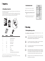
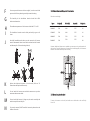
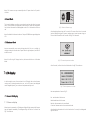
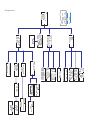
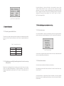
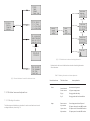
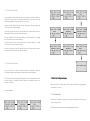
Growatt 10000UE Growatt 12000UE Growatt 18000UE Growatt 20000UE Installation GROWATT NEW ENERGY CO., LTD No.12 Building, Xicheng Industrial Zone, Bao’an District, Shenzhen, P. R.China T F E W + 86 755 2747 1900 + 86 755 2749 1460 [email protected] www.ginverter.com & Operation Manual Directory 1 Introduction 1.1 Validity 1.2 Target Group 1.3 Product Overview 1.4 Safety 2 Unpacking 2.1 Unpacking and Inspection 2.2 Information of Label 3 Mounting 3.1 Selecting Mounting Location 3.2 Dimensions and Required Clearances 3.3 Mounting the Bracket 3.4 Mounting Inverter 4 Electrical connections 4.1 Wiring AC Output 4.2 Wiring DC Input 5 Commissioning 6 Operation Modes 6.1Normal Mode 6.2Fault Mode 6.3Shutdown Mode Introduction 7 LCD display 1 1.1 Validity 7.1 General LCD display 7.2 Operate by knock 7.3 Data checking and parameters setting 7.4 Inverter faulty messages 8 COMMUNICATIONS This installation guide contains installation, commissioning, communication, trouble shooting. information of Growatt UE series inverters: Growatt 10000UE Growatt 12000UE Growatt 18000UE Growatt 20000UE 8.1 ShineNet monitoring software 8.2 Bluetooth Module (opt) 8.3 ShineLogger With this installation guide, users are able to install and operate the inverters easily.This manual does not cover any details concerning equipment connected to the Growatt UE.Store this manual where accessible at all times. 8.4 Shine GPRS collector 1.2 Target Group 9 TROUBLE SHOOTING This manual is for qualified persons such as PV system installers or electricians. 9.1 General question 9.2 Error Messages displayed on LCD 10 SPECIFICATIONS 11 Growatt Factory warranty 12 Warranty conditions Notes : For possible changes in this manual, Growatt New Energy Co., Ltd accepts no responsibilities to inform the users. 1.3 Product Overview Growatt UE series inverters are grid-tied inverters which convert DC current 13 generated by PV modules into AC current and feed it into the public grid in threephase. Growatt UE series inverters are multi-string inverters with multi-MPP trackers, Scope of the factory warranty which mean they are able to connect to different PV module arrays. Inverters Overview: DANGER! Danger to life due to high voltages in the inverter! All work on the inverter may be carried out by qualified personnel only. The appliance is not to be used by children or persons with reduced physical, sensory or mental capabilities, or lack of experience and knowledge, unless they have been given supervision or instruction. Children should be supervised to ensure that they do not play with the appliance. CAUTION! Grid-tied PV system Overview: Input A Danger of burn injuries due to hot enclosure parts! DC Breaker GROWATT UE Inverter AC Breaker Energy meter Public grid During operation, the upper lid of the enclosure and the enclosure body may become hot. Only touch the lower enclosure lid during operation. CAUTION! Possible damage to health as a result of the effects of radiation! Input B DC Breaker Do not stay closer than 20 cm to the inverter for any length of time. As drawings shown above, a complete Grid-tied PV system consists of PV modules, PV inverters, public grid and other components. Moreover, PV inverters always act as key components. When design a PV system contains Growatt UE series inverters or any other Growatt inverters, the system designing software ShineDesign (download from site: www.ginverter.com) will provide adequate supports. Notes : If PV modules of the PV system require POSITIVE or NEGATIVE GROUND, or the capacity relative to ground of the modules is large, please contact Growatt New Energy for technical support before installation. 1.4 Safety Growatt UE is designed to use worldwide, hence the inverters meet different safety standards of variety countries and regions: VDE0126-1-1 AS4777 Dk5940 Grounding the PV generator Comply with the local requirements for grounding the PV modules and the PV generator. Growatt recommends connecting the generator frame and other electrically conductive surfaces in a manner which ensures continuous conduction and ground these in order to have optimal protection of the system and personnel. CAUTION! Possible damage the PV modules as a result of Identification of String Failure! The GROWATT UE Inverter is equipped with a system which recognizes total failure of individual strings or part-strings. 2 Unpacking 2.2 Information of Label The label contains information as below: 2.1 Unpacking and Inspection The inverter type/model (Model Name); Before opening the packing box of Growatt UE, please note that whether there are any visible external damages. Once open the packing box, please check the delivery for completeness and for any visible external damages of the inverter. If there are anything damaged or missing, please contact your dealer. Complete delivery should contain as follows: A The certificates and approvals (Certificate Number and Logos at the bottom of the label); Specifications of the inverter (From U DCmax to Operation Ambient Temperature. C B E D 3 Mounting F G H 3.1 Selecting Mounting Location This is guidance for installer to choose a suitable installation location, to avoid potential damages to device and operators. Item Number Description A 1 Growatt UE inverter B 1 Mounting frame C 6/8 Expansion bolt D 6/8 Screw washer E 6/8 Spring washer F 6/8 Nut G 2 Handle H __ 1 AC connector 1 User manual (not shown in the picture) Hint: Number of C/D/E/F is 6 for Growatt 10000/12000UE, and 8 for Growatt 18000/20000UE. Notes : Though the packaging box of Growatt UE is durable, please treat the packing box gently and avoid dispose the packing box. A The wall selected to install the inverter must be strong and firm enough to support and bear the weight of the inverter for a long period time. (Refer to Chapter 10 Specifications) B The location selected must be suitable for inverters’ dimension. (Refer to 3.2 Dimensions and Required Clearances) C D Do not install the inverter on structures constructed of flammable or thermolabile materials. E Never install the inverter in environment of little or no air flow, nor dust environment. That may derate the efficiency of the cooling fan of the inverter; hence derate the efficiency of PV inverter.The cooling fans and air grills should be cleaned every half or a year. The Ingress Protection rate is IP65 which means the inverter can be installed outdoors and indoors. F G H I J Do not expose the inverter to direct sunlight, in order to avoid the power and efficiency derating caused by excessive heating. 3.2 Dimensions and Required Clearances Dimensions and weight : The humidity of the installation location should be 0~95% without condensation. The ambient temperature of the inverter should be -25℃~+60℃. Types Height(H) Width(W) Depth(D) Weight/kg 10000UE 740 440 235 41 The installation location must be freely and safely to get at all times. 12000UE 740 440 235 41 18000UE 740 520 235 60 Vertically installation and make sure the connection of inverter must be downwards. Never install horizontal and avoids forward and sideways tilt.(Refer to drawings below) 20000UE 740 520 235 60 However, additional clearances are needed to guarantee running and operation of the inverters. Especially when several inverters are installed together, the clearances between the inverters and objects are necessary. K Notice the minimum clearances of the inverter. (Refer to 3.2 Dimensions and Required Clearances). L Do not install the inverter near television antenna or any other antennas and antenna cables. 3.3 Mounting the Bracket M Do not install the inverter in living area, the noise caused by the machine may affect on daily life. To mount the inverter on the wall, we should mount the bracket to the wall firmly first of all. N For security reasons, DON’T install the inverter in place where the children can reach. Overview of the Bracket: 3.4 Mounting Inverter After the bracket is firmly mounted on the wall, then mount the inverter on the bracket. Rise up the Growatt UE a little higher than the bracket. Considered the weight of Growatt UE, you need handles (items G shown in chapter 2.1) to hang on the inverter. During the process please maintain the balance of the Growatt UE. Hang the inverter on the bracket through the match hooks on bracket and the back of the inverter. Hint: Data units in mm Steps: Drill holes for screws while use the mounting frame as template.6 holes for Growatt 10000/12000UE and 8 for Growatt 18000/20000UE. Fix the mounting frame on the wall as the figures shown below, combine as the screws as the Items overview picture shows (items C, D, E, F). Electrical connections 4 4.1 Wiring AC Output Measure the public grid voltage and frequency (Voltage: 400Vac; Frequency: 50Hz/60Hz; in 3-Phase); Open the breaker or fuse between the PV inverter and utility; Notes : Never mount the inverter on the bracket unless you are sure that the mounting frame is really firmly mounted on the wall after carefully checking. * Screw torsional force is 8 kg/cm; * Specification of AC breaker: Growatt 10000UE/ 12000UE: 32A/400V Growatt 18000UE/ 20000UE: 63A/400V Cable requirements: AWG no. Model _(mm) Area(mm²) 10000UE _2.05 3.332 12 12000UE _2.05 3.332 12 18000UE _2.59 5.260 10 20000UE _2.59 5.260 10 4 3 5 Notes : The connector must be screwed firmly. Before you operating and wiring the AC output, please make sure that the AC breaker has been turned off (open). The interface of the connector: E Notes : Detailed information of the connector refer to the manual of the connector in package. N 1 4.2 Wiring DC Input The open circuit voltage of each string should never exceed 1000Vac, while the length must be less than 30m; 3 2 The diagram drawing of DC side is shown as below, notice that the connectors are in paired (male and female connectors). The connectors for PV arrays and inverters are MC (multi-connector) connectors; Connect cables to relative bolts shown in figure above , specifications of cables must meet the requirements shown in the table above; Assemble the connector as figures shown below; 1 2 Connect the positive and negative terminals from the PV panels to positive and negative terminals on the PV inverter. The maximum string currents are varying from different inverter types Commissioning 5 A If the inverter is connected with PV panel arrays and the input voltage is higher than 300Vac, while the AC grid is not connected yet, LCD will display messages in order as below: Company info Basic info State info The LCD will repeat clue to No AC connection at State info and the LED turns red. In State info, operate by knocks will change the LCD display: Type Max. current 10000UE 15Adc 12000UE 17Adc 18000UE 23Adc 20000UE 25Adc State info (knock) Input info (knock) Output info power curve (knock) E_day B Turn on the AC breaker or close the fuse between inverter and grid, the system will operate normally. C Under normal operating conditions, the LCD displays ‘Power: xx.xx Kw’ at State info, this is the power fed into grid. The LED turns green. D Finish commissioning. Cable requirements: AWG no. Model _(mm) Area(mm²) 10000UE _2.05 3.332 12 12000UE _2.05 3.332 12 18000UE _2.05 3.332 12 20000UE _2.05 3.332 12 Notes: Under any conditions the total circuit current should never exceed the Max. Current. Notes: To reduce the risk of electric shock, avoid touching the live components and treat the terminals carefully. Operation Modes 6 6.1 Normal Mode In this mode, the inverter works normally and LED turns green. Whenever the DC voltage is higher than 350Vac, inverter converts power to grid as generated by the PV panels; Whenever the DC voltage is lower than 300Vac, the inverter will work in waiting state and attempt to connect the grid. In waiting state the inverter consumes just enough power generated by the PV panel to monitor the internal system status; Notes: The inverter starts up automatically when DC power from the PV panel is sufficient. 6.2 Fault Mode The internal intelligent controller can continuously monitor and adjust the system status. If inverter finds any unexpected conditions such as system fault and inverter fault, the fault information will be displayed on the LCD. In fault mode the LED turns red. Notes: Detailed fault information refers to Chapter 9.2 ERROR messages displayed on LCD. Fig7.1:Power on Growatt Logo After displaying Growatt Logo for 2 seconds, LCD screen will switch to the second interface, display the figure of inverter, company name, inverter’s power rating, etc. The second interface will last for 3 seconds. See Fig7.2 for reference. 6.3 Shutdown Mode Inverters automatically stop running during periods of little or no sunlight. In shutdown mode the inverters take no power from the grid and panel, and the LCD and LED turns off. Notes: If the PV string DC voltage is too low, the inverter will also turn to Shutdown Mode. Fig 7.2:The second power on interface After 3 seconds, it will switch to the third interface. See Fig7.3 for reference. 7 LCD display In the lower right corner of inverter there is the LCD display. We can check inverter running status, historical generation data, etc, on the LCD screen. Items displayed can be changed by knock, you can also set some parameters by knock. Fig7.3:The third power on interface Here are explanation of items on Fig7.3: 7.1 General LCD display No. : serial number of this inverter. Model:model name of this inverter. 7.1.1 Power on display When inverter is powered on, LCD background light will light automatically. Growatt Logo will appear immediately. The background light will last for 2 seconds. See Fig7.1 for reference. Main Ver: firmware version of control board Comm Ver: firmware version of communication board . After displaying information of the third interface for 3 seconds, the background light will turn off. LCD Display Overview 7.1.2 LCD Display when background light off Interface 3: Output information. See Fig7.6 for reference. This interface displays output information of inverter, including output voltage of each phase, output current of each phase, and output power of each phase. After the power on information is displayed automatically and the background light turns off, the LCD display will switch to the following Interface 1. There are 4 interfaces, which can be displayed in turn by single knock. Interface 1: Running status. See Fig 7.4 as reference. The first line displays inverter’s status description, for example, in faulty state it will display ERROR and followed with faulty codes, which is convenient to compare with error code list in manual. The second line displays inverter’s states name; and the third line displays energy generated today, and the forth line displays the total energy generated since installation. Fig7.6:Interface 3: Output information V: output voltage of each phase I: output current of each phase P: output power of each phase Interface 4: 24 hour’ generation curve. See Fig7.7 for reference. This interface shows the generated power of every hour this day. Fig7.4:Interface 1: Running status Interface 2: Input information. See Fig7.5 for reference. This interface displays parameters of PV input, including input voltage, current, and power of each MPP tracker. V-pv: input voltage of MPPT1 and MPPT2 I-pv: input current of MPPT1 and MPPT2 W-pv: input power of MPPT1 and MPPT2 Fig7.7:Interface 4: 24 hour’s generation curve Max: maximum power of today Power curve: today’s power curve 7.1.3 Connecting messages When inverter started to connect to grid, the following message will appear on LCD screen. See Fig7.8 for reference. Fig7.5:Interface 2: Input information During cloudy days or in the area of low light, it’s inconvenient for users to check inverter running information such as status, input data, output data, energy generated. In this case user can light the background and check those data by single knock, a single knock will switch LCD screen to a following interface. The interface display on LCD screen will circle as follows: Fir7.4 -> Fig7.5 -> Fig 7.6 -> Fig7.7 -> Fig7.8, and then again Fig7.4. Fig7.8 Connect to gird interface 7.3 Data checking and parameters setting 7.2 Operate by knock 7.3.1 First level menu 7.2.1 Knock type and definition It is a little bit different to enter the first level menu, note that using thrice knock to enter first level menu instead of double knock. Fig 7.9 is interface of first level menu. The inverter can support three kinds of knock: single knock, double knock and thrice knock. Each kind of knock has different function. Refer to specified definition in Table 7.1. Table 7.1 Knock definition list Knock type Definition Single knock Double knock KeyDown KeyEnter Thrice knock KeyEsc 7.2.2 Light background light and single knock to check running information Fig 7.9 First level menu In this interface, a single knock will switch the index to next item, a double knock will enter the corresponding second level menu. 7.3.2 Second level menu In first level menu, double knock will lead to next level menu. Before light the background light, the three types of knock functions the same, which is just lighting the background.: just light the background . Note that the background lighting will automatically turn off if there is no knock detected in 10 seconds. The followings are second level menu interfaces for each first level menu items, shown in Fig 7.10 In second level menu, a single knock will switch the index to next item, a double knock will enter the corresponding third level menu. And a thrice knock will back to first level menu. Double knock Single knock Double knock Double knock Double knock Single knock Double knock Single knock Single knock Double knock Fig 7.11 Third level menu interface of working information Explanations of each items in third level menu interface of working information: State information: Table 7.2 Working information sub-items explanation Fig 7.10 Second level menu for each first level menu items Second level menu State 7.3.3 Third level menu and explanations Third level items Item explanation State: Normal Inverter running status Power: xxx.xx AC gross output power E_day Energy produced today E_all Energy produced since installation 7.3.3.1 Working information Input The followings are third level menu interfaces for each second level menu items of working information, shown in Fig 7.11 Power: xxx.xx Gross input power from PV panel V-pv xxx/xxx PV input voltage for each MPP tracker I-pv xx.x/xx.x PV input current for each MPP tracker W-pv xxx/xxx PV input power for each MPP tracker Second level menu Output Power line Third level items Item explanation Explanation of each items in third level menu interface of working information: State information: Table 7.3 Historical information sub-items explanation Power: xx.xx AC output gross power V: xxx.xxx.xxx AC output voltage for each phase I: xx.x/xx.x/xx.x AC output current for each phase P: xxx/xxx/xxx AC output power for each phase Power: xx.x AC output current power Error3: xxx Max: xx.x AC output maximum power Error4: xxx Power curve AC output power curve Second level menu Error Record Third level items Error1: xxx Item explanation Display 4 latest error record. Error2: xxx E in 7Days 7 Days Title indicate this is latest 7 days running data 7.3.3.2 Historical information The followings are third level menu interfaces for each second level menu items of historical information, shown in Fig 7.12 E in This Year MM:DD: xxxx.x Format is Month:Date, xxxx.x is Kwh energy generated in that day. Month Title indicate this is every month’s running data in this year MM: xxxx.x Kwh Double knock xxxx.x is energy generated in that month. E in Each Year Year Title indicate this is latest 10 years running data 20XX: xxxx.x Kwh xxxx.x is energy generated in the corresponding year. Double knock 7.3.3.3 Property information Double knock The followings are second level menu interfaces of property, shown in Fig 7.13 Double knock Double knock Double knock Single knock Fig 7.12 Third level menu interface of historical information Fig 7.13 Property information Explanation of each items in third level menu interface of working information: State information: Table 7.4 Property information First level menu Property Second level items Item explanation No.:xxxxxxxxxx Serial number of this inverter Model:PxUxMxSx Odel name of this inverter Main Ver:D.0.1 Comm Ver:C.0.1 2011-01-01 Date time 07:00:00 System time 7.3.4 Parameters set and auto test The followings are setting information in second level menu and its submenus,shown in Fig 7.14 7.3.4.1 Set inverter’s COM address When communicating with monitoring software or device, the software or device may regard inverter’s COM address as communication address (Also may use inverter’s serial number as communication address).The COM address could be assigned random or fixed. The second level menu “Set COM address” of setting is to set inverter’s COM address. Set random COM address : Setting->Set COM addr->Set Auto, then LCD screen will display “Set OK, Mode: Auto, COM addr: xxx”, see Fig 7.14 for reference. Set fixed COM address: Setting->Set COM addr->Set Manual, then single knock to change value of fixed address, double knock will save changes, and LCD screen will display “Set Addr OK! Current Addr XXX”, see Fig 7.14 for reference. 7.3.4.2 Set language To change inverter’s displaying language, please select Setting->Set language, then LCD screen will display current language type, single knock to change current language, double knock will save changes and displays “Set Language OK! Current Language English” see Fig 7.14 for reference. Please note in order to prevent misoperation, system language won’t be change in second level menu “Set language”, but it will be only if user saves save the choice by double knock and LCD displays “Set OK!” The inverter provides five languages: Italian, English, German, Spanish, and French. The number on Set language interface is sequence number of these five languages, the sequence number and its corresponding language are shown in Table 7.5 Table7.5 sequence number of languages Language Fig 7.14 setting second level menu and its sub-menus Sequence Number Italian 0 English 1 German 2 Spanish 3 French 4 7.3.4.3 Set inverter time 4 5 6 9 8 7 10 11 12 Inverter provides a system clock; user must set the system time after installation, as the historical statistic data for a period were based on the clock. User can set the following time parameters: year, month, day, hour, minute. Set year: Setting->Set time->Set year->Year up or Year down->knock to change year. Thrice knock to exit and save changes. Set month: Setting->Set time->Set month->Month up or Month down->knock to change month. Thrice knock to exit and save changes. Set date: Setting->Set time->Set date->Date up or Date down->knock to change date. Thrice knock to exit and save changes. Set hour: Setting->Set time->Set hour->Hour up or Hour down->knock to change Hour. Thrice knock to exit and save changes. Set minute: Setting->Set time->Set minute->minute up or minute down->knock to change minute. Thrice knock to exit and save changes. 7.3.4.4 Auto test function 13 Auto test function is to check the inverter's protection when grid is abnormal, including over voltage, under voltage, over frequency, and under frequency. To run auto test function please select Setting->Auto test, then double knock to start auto test function. It’s required to connect inverter to computer and run a test software in computer. 7.4 Inverter faulty messages When system fault or inverter error occurs, inverter will display faulty message or error code on LCD screen. Auto test procedure 7.4.1 System fault 1 2 3 System fault is related to the solar system, it may be caused by PV panels wiring, AC wiring, or AC grid faults. The followings are all system faulty messages displayed on inverter: System fault message may display on LCD Communication Explanation and suggestion Auto Test Failed Auto test didn’t pass No AC Connection No utility, no grid connected PV Isolation Low Insulation problem. Residual I High GFCI current high Output High DCI Output current DC offset too high PV Voltage High PV panel voltage too high AC V Outrange Grid voltage out of range AC F Outrange Grid frequency out of range 8 8.1ShineNet monitoring software ShineNet is PC software designed to collect data from Growatt Inverters with strong analytical function. It has multi-communication channels and completed data analysis function. Users are able to monitor the status of Growatt inverters in realtime, browse and analysis the history data that has been recorded. Notes: Users are able to monitor the inverter after the setting of software. Detailed information about setting and functions refer to the ShineNET Manual. 8.2 Bluetooth Module (opt) Bluetooth module is an external device that can be plugged into inverter via RS232 port. Bluetooth RS232 Configuration is a parameter setting software of Bluetooth module to set configuration such as device name, flow control method, encryption password (pair code), etc. 7.4.2 Error message Inverter errors are problems come from interior inverter. DISPLAY OPERATION Error: 100 Fan fault Error: 101 Communication fault Error: 103 EEPROM fault Error: 104 Model Fault Error: 109 Input Current Out of range Error: 110 Output Current Out of range Error: 117 Relay Fault Error: 119 GFCI Fault Error: 120 UHCT Fault Error: 122 Bus voltage out of range Pic: Notes: Before delivery, the Bluetooth module is set to the default configuration parameters: Baud rate 9600 bps Parity bit None Data bit 8 Stop bit 1 Flow control None Master/Slave devices Slave device Bind address None Pair code 1234 Hint: Pair code is encryption password. Customers DON’T need to set the configuration again. Detailed information of configuration and operation refer to Bluetooth module Introduction. This device is optional. Pic: 8.3 ShineLogger ShineLogger is an inverter monitoring product of Growatt New Energy Co., Ltd. It can collect and analyze running data of inverter via Bluetooth connection, and display monitoring data on LCD screen; user can also browse data on computer as well. ShineLogger can monitor up to 4 inverters simultaneity. ShineLogger has standard data communication interface, including RS232/RS485 serial port, USB port, and Bluetooth, it will be compatible with you existing systems smoothly. Pic: Notes: To assure the regular running of collector, user should make sure the GSM signal is stability. Indoor installation only. Detailed information refers to Shine GPRS collector manual. Trouble shooting 9 Notes: Indoor installation. Detailed information refers to ShineLogger Manual. 8.4 Shine GPRS collector PV power station remote data acquisition unit (GPRS data collector) collects inverter operation data, including PV input voltage, PV input current, AC output voltage, AC output current, frequency, output power, etc. via RS-485/RS232 connection and send the above data to website via GPRS, so that users can check power station’s real time status by login to website www.growatt.net, also can browse historical data in the past. Our quality control program assures that every inverter is manufactured to accurate specifications and is thoroughly tested before leaving our factory. If you have difficulty in the operation of your inverter, please read through the following information to correct the problem. 9.1 General question For General question, please visit www.ginverter.com, and find the Q&A column. 9.2 Error Messages displayed on LCD Error message An error message will be displayed on the LCD screen when a fault occurs. The faults consist of system fault and inverter fault. AC F Outrange You may be advised to contact Growatt in some situation, please provide the following information. Information concerning the inverter: • Serial number • Model number • Error message on LCD • Short description of the problem • Grid voltage • DC input voltage • Can you reproduce the failure? If yes, how? • Has this problem occurred in the past? • What was the ambient condition when the problem occurred? Description Suggestion Utility grid frequency 1.Check firmware version (Please out of permissible refer to LCD display section). range. If firmware version is below G.1.3, contact Growatt. 2.Check grid frequency. 3.If the error message is displayed despite the grid frequency being within the tolerable range, contact Growatt. PV Isolation Low Insulation problem 1.Check if panel enclosure ground properly. 2.Check if inverter ground properly. 3.Check if the DC breaker gets wet. Information concerning the PV panels: • Manufacturer name and model number of the PV panel • Output power of the panel • Voc of the panel • Vmp of the panel • Imp of the panel • Number of panels in each string If it is necessary to replace the unit, please ship it in the original box. 4.Check the impedance of PV (+) & PV (-) between ground (must be more than 8 MΩ). If the error message is displayed despite the above checking passed, contact Growatt. Residual I High 9.2.1 System fault Leakage current 1.Restart inverter. too high 2.If error message still exists, contact Growatt. System fault (system faults are mainly caused by system instead of inverter, please check the items as instructed below before replacing inverter) Error message No AC Connection Description No utility grid connected or utility grid power failure. AC V Outrange Output current DC 1.Restart inverter. offset too high 2.If error message still exists, contact Growatt. Suggestion 1.Check AC wiring, especially the ground wire. PV Voltage High 2.Contact Growatt Utility grid voltage I 1.Check grid voltage. s out of permissible 2.If the error message still exists range. Output High DCI despite the grid voltage being within the tolerable range, contact Growatt. The DC input voltage Disconnect the DC wire is exceeding the immediately. maximum tolerable value. Auto Test Failed Auto test didn’t passed Reboot inverter. 9.2.1 Inverter fault Error code Meanings Error code Suggestion Error: 120 Error: 100 Suggestion Meanings For 18K/20K inverter: 1.Replace faulty fan. Problem with fan No.4. 2.If problem still exists after For 8K/10K inverter: replacement, contact Growatt. Output current detection Error: 121 Control board has not Electromagnetic Interference too received data from strong, contact Growatt. Communication board Problem with No. 2 fan. for 5S. Note: If there is problem with other fans, inverter Error: 122 continue running with Bus voltage out of range. warning on LCD showing: Communication board has 2.If input voltage is around 1000V, reboot the inverter with lower not received data from DC supply, and Error message will disappear. seconds. Electromagnetic 2.If the error 101 is often displayed, Interference cause the environment Electromagnetic Interference is too strong. Contact Growatt. Error: 103 EEPROM fault. Contact Growatt. Error: 104 Model setting fault. Reason Contact Growatt.. can be Model and safety set correctly. Input current out of 1.Check input current is within tolerable range or inverter’s the tolerable range. component is damaged. 2.If error message still exists despite the checking was passed, contact Growatt. Error: 110 Inverter’s component is damaged. Error: 117 Error: 119 Relay fault GFCI fault. 3.If error message still exists, contact Growatt. 10 Specifications 10000UE 12000UE 18000UE 20000UE Max. DC power 10200W 12250W 18400W 20000W Max. DC voltage 1000V 1000V 1000V 1000V PV voltage range MPPT 400V-800V 400V-800V 400V-800V 400V-800V Max. input current (input A/input B) 15A / 15A 17A / 17A 22A / 22A 25A / 25A Number of MPP trackers 2 2 2 2 Max. number of parallel strings 2/2 2/2 2/2 2/2 DC Connections MC4(optional MC3) MC4(optional MC3) MC4(optional MC3) MC4(optional MC3) Input Data requirement have not been Error: 109 input voltage. 1.Reboot inverter by cutting off control board for 10 communication problem. 1.Check if input voltage is within the voltage range. Fan Error. Error: 101 Contact Growatt fault. Contact Growatt. Contact Growatt Contact Growatt Growatt Factory warranty 11 10000UE 12000UE 18000UE 20000UE Max. AC power 10KVA 12KVA 18KVA 19.5KVA Nominal output power 10KW 12KW 18KW 19.5KW Max. output current (over 110%) 16A 19A 28.6A 32A AC voltage range 3 / N / PE 230V / 400V 3 / N / PE 230V / 400V 3 / N / PE 230V / 400V 3 / N / PE 230V / 400V AC grid frequency range 50 /60 Hz-6Hz / +5Hz 50 /60 Hz-6Hz / +5Hz 50 /60 Hz-6Hz / +5Hz 50 /60 Hz-6Hz / +5Hz Phase shift (cos φ) 0.8leading0.8laging 0.8leading0.8laging 0.8leading0.8laging 0.8leading0.8laging AC output THD <3%(normal power output) <3%(normal power output) <3%(normal power output) <3%(normal power output) AC connection Three phase Three phase Three phase Three phase Consumption(night) <1W <1W <1W <1W Ground failure detection Yes Yes Yes Yes Max . efficiency 98% 98% 98% 98% Euro-eta 97% 97% 97% 97% (Applicable under normal application, installation, use and service conditions) Growatt warrants the above listed products to be free from defects and/or failure the Proof of Purchase to the Original purchaser. Output Data Efficiency 440/740/235 440/740/235 520/740/235 520/740/235 Weight 41 KG 41 KG 60 KG 60 KG Ambient temperature range –25°C..+60°C –25°C..+60°C –25°C..+60°C –25°C..+60°C Continuous full output power temperature range –25°C..+45°C Cooling concept Fans –25°C..+45°C –25°C..+45°C –25°C..+45°C Growatt 1500, Growatt 2000, Growatt 3000, Growatt 4000, Growatt 5000, Sungold 1500, Sungold 2000, Sungold 5000, Growatt 3600MTL, Growatt 4200MTL, Growatt 5000MTL Growatt 3600MTL-US, Growatt 4200MTL-US, Growatt 5000MTL-US Growatt 10000UE, Growatt 12000UE, Growatt 18000UE, Growatt 20000UE The warranties described in these “Limited Warranties ” are exclusive and are expressly in lieu of and exclude all other warranties, whether written, oral, express or implied, including but not limited to, warranties of merchantability and of fitness the part of GROWATT , unless such other obligations or liabilities are expressly agreed to it in writing signed and approved by GROWATT , GROWATT shall have no yes/yes Fans yes/yes Fans yes/yes Fans yes/yes RS232/Blue tooth /R485 RS232/Blue tooth /R485 RS232/Blue tooth /R485 Yes(Alphanumeric 4 lines) Yes(Alphanumeric 4 lines) Yes(Alphanumeric 4 lines) Yes(Alphanumeric 4 lines) Isolation Transformerless Transformerless Transformerless Transformerless Warranty: 5 years / 10 years Yes / Opt Yes / Opt Yes / Opt Yes / Opt TUV,UL,AS TUV,UL,AS TUV,UL,AS TUV,UL,AS Certificates and approvals This warranty is applicable solely to the following products: for a particular purpose, use ,or application, and all other obligations or liabilities on RS232/Blue tooth /R485 LCD display Warranted products specified for a period not exceeding five (5) years from the date of sale as shown in Dimensions (W / H / D) in mm Communication from the date of purchase. Limited Product Warranty General Data Installation: Indoors / Outdoors(IP 65) This certificate represents a 5 year warranty for the Growatt inverter products listed below. Possession of this certificate validates a standard factory warranty of 5 years responsibility or liability whatsoever for damage or injury to persons or property, or for other loss or injury resulting from any cause whatsoever arising out of or related to the modules, including, without limitation, any defects in the modules or from use or installation. Under no circumstances shall GROWATT be liable for incidental , consequential or special damages howsoever caused; loss of use, loss of production, loss of revenues are therefore specifically and without limitation excluded to the extent legally permissible, GROWATT ’s aggregate liability, if any, in damages or otherwise, shall not exceed the invoice as paid by the customer. 12 Warranty conditions The “ Limited Product Warranties ” described above shall not apply to, and Growatt shall have no obligation of any kind whatsoever with respect to, any inverter which has been subjected to: Misuse, abuse, neglect or accident; If a device becomes defective during the agreed Growatt factory warranty period and provided that it will not be impossible or unreasonable, the device will be, as selected by Growatt, Alteration, improper installation or application; Unauthorized modification or attempted repairs; 1. Shipped to a Growatt service center for repair, or Insufficient ventilation of the product; Transport damage; 2. repaired on-site, or Breaking of the original manufacturers seal; Non-observance of Growatt installation and maintenance instruction; 3. exchanged for a replacement device of equivalent value according to model and age. Failure to observe the applicable safety regulations Power failure surges, lighting, flood, fire, exposure to incorrect use, negligence, accident, force majeure, explosion, terrorist act, vandalism or damage caused by incorrect installation, modification or extreme weather conditions or other circumstances not reasonably attributable to Growatt. The warranty shall also cease to apply if the product cannot be correctly identified as the product of Growatt. Warranty claims will not be honored if the type of serial number on the inverters have been altered, removed or rendered illegible. Liability The liability of Growatt in respect of any defects in its PV inverters shall be limited to compliance with the obligations as stated in these terms and conditions of warranty. Maximum liability shall be limited to the sale price of the product. Growatt shall accept no liability for loss of profit, resultant of indirect damage, any loss of electrical power and / or compensation of energy suppliers within the express meaning of that term. The warranty rights as meant herein are not transferable or assignable to any third party excepting the named warranty holder. The warranty shall not cover transportation costs in connection with the return of defective modules. The cost of the installation or reinstallation of the modules shall also be expressly excluded as are all other related logistical and process costs incurred by all parties in relation to this warranty claim. 13 Contact If you have technical problems concerning our products, contact your installer or Growatt. During inquiring, please provide below information: 1. Inverter type 2. Modules information 3. Communication method 4. Serial number of Inverters 5. Error code of Inverters 6. Display of inverters GR - UM - 003 - 00


![Fronius Primo:, , [42,0426,0204,PB]](http://vs1.manualzilla.com/store/data/006066638_1-53eaca308649d96bdc628a0452b266c5-150x150.png)

