1
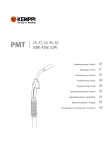
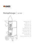
��������������������������������
����������������������������
�������������������������������
�������������������������������
1922430E
CONTENTS
1.
PREFACE ......................................................................................................................3
1.1. Introduction ..........................................................................................................3
1.2. Product introduction .............................................................................................3
1.3. Operation safety...................................................................................................3
2.
INSTALLATION .............................................................................................................4
2.1. Transport and lifting of the equipment..................................................................4
2.2. Siting the machine ...............................................................................................4
2.3. Connection to the mains supply...........................................................................4
2.4. Welding and return current cables .......................................................................5
3.
OPERATION AND USE CONTROLS............................................................................5
3.1. Main switch ..........................................................................................................7
3.2. Signal lamps ........................................................................................................7
3.3. Adjustment for MMA dynamics ............................................................................7
3.4. Control fuse..........................................................................................................7
3.5. Operation of cooling fan.......................................................................................7
3.6. Adjustment for MIG/MAG welding........................................................................7
4.
ACCESSORIES .............................................................................................................8
4.1. V/A meter unit MSD 1 ..........................................................................................8
4.2. Cooling unit functions in Kempomig 4000WR......................................................8
4.2.1. Installation of cooling................................................................................................8
4.2.2. Operation .................................................................................................................9
4.2.3. Operation disturbances of the cooling unit...............................................................9
5.
6.
7.
MAINTENANCE...........................................................................................................10
5.1. Cables................................................................................................................10
5.2. Power source .....................................................................................................10
5.3. Regular maintenance.........................................................................................10
ORDERING NUMBERS...............................................................................................11
TECHNICAL DATA ......................................................................................................12
2 KEMPOMIG 4000R, 4000WR - 0409
© COPYRIGHT KEMPPI OY
1.
PREFACE
1.1.
INTRODUCTION
Congratulations on having purchased this product. Properly installed Kemppi products should
prove to be productive machines requiring maintenance at only regular intervals. This manual is
arranged to give you a good understanding of the equipment and its safe operation. It also contains
maintenance information and technical specifications. Read this manual from front to back before
installing, operating or maintaining the equipment for the first time. For further information on
Kemppi products please contact us or your nearest Kemppi distributor.
The specifications and designs presented in this manual are subject to change without prior
notice.
In this document, for danger to life or injury the following symbol is used:
Read the warning texts carefully and follow the instructions. Please also study the Operation safety
instructions and respect them when installing, operating and servicing the machine.
1.2.
PRODUCT INTRODUCTION
Kempomig 4000R and 4000WR are DC power sources for demanding professional use in MIG/
MAG welding.
They are inverter power sources for 400 V 3-phase electric mains. Kempomig 4000WR is equipped
with inbuilt cooling unit for water-cooled MIG guns. Parameter adjustments for MIG/MAG
welding are made from Feed 420R wire feeding control unit, which is connected to Kempomig
power sources.
1.3.
OPERATION SAFETY
Please study these Operation safety instructions and respect them when installing, operating and
servicing the machine.
Welding arc and spatter
Welding arc hurts unprotected eyes. Be careful also with reflecting arc flash. Welding arc and
spatter burn unprotected skin. Use safety gloves and protective clothing.
Danger for fire or explosion
Pay attention to fire safety regulations. Remove flammable or explosive materials from welding
place. Always reserve sufficient fire-fighting equipment on welding place. Be prepared for hazards
in special welding jobs, e.g. for the danger of fire or explosion when welding container type work
pieces. Note! Fire can break out from sparks even several hours after the welding work has been
finished!
Mains voltage
Never take welding machine inside a work piece (e.g. container or truck). Do not place welding
machine on a wet surface. Always check cables before operating the machine. Change defect cables
without delay. Defect cables may cause an injury or set out a fire. Connection cable must not be
compressed, it must not touch sharp edges or hot work pieces.
Welding power circuit
Isolate yourself by using proper protective clothing, do not wear wet clothing. Never work on a
wet surface or use defect cables. Do not put MIG gun or welding cables on welding machine or
on other electric equipment. Do not press MIG gun’s switch if the gun is not directed towards a
work piece.
Welding fumes
Take care that there is sufficient ventilation during welding. Take special safety precautions when
welding metals which contain lead, cadmium, zinc, mercury or beryllium.
© COPYRIGHT KEMPPI OY
KEMPOMIG 4000R, 4000WR - 0409 3
2.
INSTALLATION
2.1.
TRANSPORT AND LIFTING OF THE EQUIPMENT
On the power source´s front panel and above the wire feeder unit there are handles for moving the
units on the floor.
Make sure that the unit is kept between lifting linens during lifting. When necessary,
use additional binding round the lifting linens and the unit´s upper part. Use protection
between the lifting device and the unit in order to eliminate impacts and shocks.
2.2.
SITING THE MACHINE
Site the machine on a stationary, horizontal, dry and clean base from which there does not come
any dust etc. into inlet air through the rear grate.
60°
EN 60974-1
rain water
max
15°
–
–
Preferably site the machine above floor level.
See to that in front of the machine as well as at the rear of the machine there is at least 20 cm
free space to allow good circulation of the cooling air through the machine.
– Protect the machine against heavy rain and in hot circumstances against direct sunshine. Ensure
free circulation of the cooling air.
Degree of protection IP23 of the machine allows a water jet coming in 60 ° angle at its maximum
to hit machine´s outer covering.
Do not direct particle spray of grinding tools towards the machine.
2.3.
CONNECTION TO THE MAINS SUPPLY
As standard, Kempomig power sources are delivered with 5 m mains cable without plug. If the
mains cable does not meet local electric regulations, you must change the cable to meet them.
Connection and change of the mains cable and plug must be carried out only by a
competent electrician.
During mounting of mains cable, remove the right side plate of the machine, seen from the
front.
When mounting the mains cable ensure the following: The cable is entered into the machine
through the inlet ring on the rear wall of the machine and locked with a cable clamp. The phase
conductors of the cable are coupled to connectors L1, L2 and L3.
Sizes of mains cables and fuse ratings for the machine at 100 % ED duty cycle are specified in the
table Technical data. In cables of S type there is protective grounding conductor coloured greenyellow.
4 KEMPOMIG 4000R, 4000WR - 0409
© COPYRIGHT KEMPPI OY
2.4.
WELDING AND RETURN CURRENT CABLES
Use only copper cables with cross-sectional area of at least 50 mm2.
Table below shows typical loading capacities of rubber insulated copper cables, when ambient
temperature is 25°C and conductor temperature is 85°C.
Cable
Duty cycle ED
100 %
60 %
285 A
370 A
355 A
460 A
430 A
560 A
50 mm2
70 mm2
95 mm2
Voltage loss / 10 m
30 %
520 A
650 A
790 A
0,35 V / 100 A
0,25 V / 100 A
0,18 V / 100 A
To avoid voltage losses and heating, do not overload welding cables over permissible
values.
Fasten the earth clamp of the return current cable carefully, preferably directly onto the work piece.
The contact surface area of the clamp should always be as large and steady as possible. Clean the
contact surface from paint and rust.
3.
OPERATION AND USE CONTROLS
Kempomig 4000R
Main switch
Signal lamp for main
switch
Welding current connector (+)
Signal lamp for
thermal protection
release
Adjustment for
MMA welding
dynamics *)
Return current connector (–)
Mounting place
for V/A meter unit
MSD1
Fuse for control
connector (6,3 A)
Accessory drawer
© COPYRIGHT KEMPPI OY
Control connector
for wire feeder unit
Accessory drawer
KEMPOMIG 4000R, 4000WR - 0409 5
Kempomig 4000 WR
Main switch
Welding current connector
(+)
Return current connector (–)
Signal lamp for
main switch
Signal lamp for
thermal protection
release
Control connector for
wire feeder unit
Adjustment for
MMA welding
dynamics *)
Fuse for control connector
(6,3 A)
V/A meter
unit MSD 1
(accessory)
Fuse for cooling unit
(2 A delayed)
Water circulation
return connector
Water circulation output
connector
Water tank
6 KEMPOMIG 4000R, 4000WR - 0409
Signal lamp for lacking
water pressure
Test switch for water
circulation
Selecting switch for gun´s
cooling mode (AIR/WATER)
Signal lamp for overheating
© COPYRIGHT KEMPPI OY
3.1.
MAIN SWITCH
When you turn the main switch at the rear wall of the machine into position I, signal lamp for
readiness of use on the front wall is lit and the machine is ready for use.
Always switch the machine on and off from the main switch. Never use the mains plug for
switching the units and equipment on or off.
3.2.
SIGNAL LAMPS
Signal lamps of the machine report on electric function:
Green signal lamp for readiness of use is always lit when the machine is connected to mains and
the main switch is in position I.
Signal lamp for thermal protection is lit, when the thermostat has been released due to
overheating. The protection is released if the power source is continuously loaded over rated values
or cooling air circulation has been obstructed. The cooling fan is cooling down the machine, and
after the signal lamp has switched off, the machine is again ready for welding.
3.3.
ADJUSTMENT FOR MMA DYNAMICS *)
On adjusting MMA dynamics, you influence the arc behaviour in drop short circuit. In max.
setting the arc is at its roughest position and in min. setting at its softest position. Zero setting is
recommendable factory setting for welding of all electrodes. When roughness of arc is increased,
blowing is also increased and amount of spatter will grow.
Soft arc. Purpose: reduction of spatter in welding at upper end of recommended currents for
electrode.
Rough arc. Purpose: e.g. thin stainless electrodes in welding at lower end of recommended currents
for electrode.
3.4.
CONTROL FUSE
On the rear wall of the power source the fuse 6.3 A, delayed, protects the control voltage supply of
the power source against the control cable´s short-circuit, or against overload caused by the wire
feeder unit. Use a fuse size and type according to markings. Damage caused by a wrong type fuse
is not covered by the guarantee.
3.5.
OPERATION OF COOLING FAN
Cooling fan is started and stopped according to use. The cooling fan is started after ca. 30 s after
weld start and stopped after ca. 5 - 7 min after weld end.
3.6.
ADJUSTMENT FOR MIG/MAG WELDING
Adjustments for MIG/MAG welding parameters are made from Feed 420R wire feeder unit which
is connected to Kempomig power source. See operation instructions for Feed 420R.
*) Feed 420R wire feeding control unit does not support the MMA welding method.
© COPYRIGHT KEMPPI OY
KEMPOMIG 4000R, 4000WR - 0409 7
4.
ACCESSORIES
4.1.
V/A METER UNIT MSD 1
The V/A meter unit MSD 1 displays during welding true value of welding current or welding
voltage. The current / voltage display is selected with selecting switch of the MSD 1.
For the mounting of the MSD 1, remove the cover plate on the front panel of the unit. The connector
of flat cable fastened to the cover plate is connected to the corresponding connector of MSD 1.
Note! MSD 1 does not display arc voltage but the machine´s pole voltage. Note that due to cable
losses, the arc voltage can be many volts lower than the machine´s pole voltage.
4.2.
COOLING UNIT FUNCTIONS IN KEMPOMIG 4000WR
Kempomig 4000WR has an inbuilt cooling unit inside the power source. Operation control switches
of the cooling unit are on the front panel of the power source and the water tank of the cooling
system is in front wall drawer.
Signal lamp for lacking water pressure
Selecting switch for gun´s cooling mode
4.2.1.
Test for water circulation
Signal lamp for overheating
Installation of cooling
1. Connect water hoses of the interconnection cable coming from the wire feeder to snap
connectors on the power source´s rear wall. The interconnection cable´s hose marked with
blue colour is for water supplied from the cooling unit to gun. The hose marked with red is for
water returning back from gun to cooling unit. Before connecting the interconnection cable,
check that in hoses there is no dirt, metal powder, rubber waste etc.
2. The cooling unit´s tank is filled with 20 - 40 % glycol / water mixture according to antifreeze
requirements. Instead of glycol / water mixture you can also use another suitable liquid
according to your experience.
3. Set the selecting switch for gun´s cooling mode on the front wall to water cooling mode and
start the power source from the main switch.
4. Press the test switch for water circulation until the signal lamp for water pressure is switched
off. Fill the water hoses for interconnection cable and gun with the test switch in question.
Check the return flow and the tank´s water line. The tank volume is ca. 3 litres, the volume for
gun and interconnection cable is 0.3 – 1.5 litres. Filling of hoses takes 5 s - 3 min.
5. Start welding in a normal way and the pump starts automatically. After the weld end the pump
is still operating for ca. 5-7 min.
If the water does not start circulating, see paragraph for Operation disturbances.
Do not let any waste or dirt get into the water circulation! Check the filling volume before
you start welding!
Use a cooling liquid according to recommendations or one you know to be good. Keep an eye
on liquid material´s quality and possible sediments in hoses and in gun.
8 KEMPOMIG 4000R, 4000WR - 0409
© COPYRIGHT KEMPPI OY
4.2.2.
Operation
Operating control
The pump starts up automatically when you pull the gun trigger. The water post-circulation
continues ca. 5 - 7 min after weld end.
When the power source’s main switch is in O position all cooling unit functions are stopped!
Cooling unit´s fuse
The fuse 2 A, delayed, on the rear wall of the power source is the short-circuit protection of the
cooling unit’s auxiliary transformer. Use a fuse size and type according to markings. If the fuse is
blown again, send the unit to service.
Selecting switch for gun´s cooling mode
- position: for air-cooled MIG gun.
- position: for water-cooled MIG gun. The pump starts up, when you pull the gun
trigger.
Note! If you have selected
- position but you are using a water-cooled gun, welding
is started by pulling the gun trigger. However, the pump will not get started. This kind
of wrong selection will destroy the gun in short time!
Test switch
With the TEST switch on the cooling unit panel you can circulate water without starting welding.
This is used for filling the gun and interconnection cable with cooling water before starting welding.
In disturbance situations you can always test the water circulation. Always check entry of return
water into the tank before welding.
Signal lamp for overheating
If the cooling water in the tank is overheating, the thermal protection will stop the power source.
Cooling unit operation continues automatically ca. 5 - 7 min. After the cooling water has cooled
down sufficiently, the signal lamp will switch off, and you can start welding as usual.
Signal lamp for lacking water pressure
If the pump does not step up sufficient supply pressure, e.g. when the water is running out or in
disturbances in the pump the whole equipment will stop after ca. 5 s and the red signal lamp is lit.
Check the equipment as upon installation. See chapter for Operation disturbances.
4.2.3.
Operation disturbances of the cooling unit
If operation or functional disturbances occur, take measures according to the following list.
If the disturbance cannot be eliminated, take contact with an authorised Kemppi repair
workshop.
The pump does not get started when pressing the TEST switch:
–
–
–
check the fuse 2 A, DELAYED, on the rear of the cooling unit
check position for cooling mode selecting switch
check position for main switch
The water is pumping but does not return back to the tank or the return flow is weak:
–
–
–
filling of interconnection cable can take several minutes
if you have lifted the gun or interconnection cable for the filling time several meters higher
than the power source, filling will take place considerably slower. Fill the hoses on the floor
position.
if there is a leakage in the interconnection cable, check the whole flowing line
The water is pumping, but during welding the red signal lamp for water pressure is lit and
the equipment is stopped:
–
–
–
check the cooling water volume and return flow to the tank
there are air bubbles or leakages in the system
pressure switch set value (ca. 1 bar) is unsuitable for the gun being used
During welding the yellow signal lamp for overheating is lit and the equipment is
stopped:
–
–
release the trigger and let the water cool down. When the lamp is switched off, the operation
has been reset automatically
check if the gun is suitable for power being used
© COPYRIGHT KEMPPI OY
KEMPOMIG 4000R, 4000WR - 0409 9
5.
MAINTENANCE
The amount of use and working environment should be taken into account when planning frequency
of maintenance of machine. Careful use and preventive maintenance will help to ensure troublefree operation.
5.1.
CABLES
Check the condition of welding and connection cables daily. Do not use faulty cables!
Make sure that the mains connection cables used are safe and according to regulations!
Repair and mounting of mains connection cables should be carried out only by an authorised
electrician.
5.2.
POWER SOURCE
NOTE! Disconnect the plug of the power source from the mains socket before removing the cover
plate.
Check at least every 6 months:
–
Electric connections of the unit - clean the oxidised parts and tighten the loosened ones. NOTE!
You must know correct tension torques before starting the repair of the joints.
– Clean the inner parts of the machine from dust and dirt e.g. with a soft brush and vacuum
cleaner.
Do not use compressed air, there is a risk that dirt is packed even more tightly into gaps of
components!
Do not use a pressure washing device!
Only an authorised electrician may carry out repairs to the machine.
5.3.
REGULAR MAINTENANCE
Kemppi service repair workshops perform regular maintenance according to agreement.
The major points in the maintenance procedure are as follows:
–
–
–
–
–
–
–
–
Cleaning of equipment
Checking and maintenance of the welding tools
Checking of connectors, switches and potentiometers
Checking of electric connections
Metering units checking
Checking of mains cable and plug
Replacing damaged parts or parts in bad connection with new ones
Maintenance testing. Operation and performance values of the equipment are checked and
adjusted when necessary with test equipment.
twice a
year
10 KEMPOMIG 4000R, 4000WR - 0409
© COPYRIGHT KEMPPI OY
6.
ORDERING NUMBERS
Power sources
Kempomig 4000R ..............................................6227400R
Kempomig 4000WR ......................................6227400WR
Accessories:
V/A metering unit MSD 1.................................... 6185666
Wire feeder units
Feed 420R ............................................................ 6236420
Feed 120R ............................................................ 6236120
Accessories:
SYNC 400............................................................ 6263120
GG 400 gas guard ............................................... 6237405
GH 10 gun holder................................................ 6256010
KV400 swing arm ................................................ 6185247
KV400 50-1.5-GH (cable) .................................. 6260351
KV400 50-1.7-WH (cable) ................................. 6260353
Hub for wheel reel ............................................... 4289880
MIG guns for robotic use
Air-cooled:
MT 38M .....................3 m ................................... 6253038
Liquid-cooled:
MT 51MW .................1,5 m / SK ........................ 6255156
MT 51MW .................1,5 m / K30 ...................... 6255157
MT 51MW .................3 m / SK ........................... 6255158
MT 51MW .................3 m / K30 ......................... 6255159
Interconnection cables
Interconnection cables Kempomig 4000R, 4000WR / Feed 420R
KW 50-1.3-GH .................................................... 6260350
Multimig 70-11-GH ............................................. 6260182
Return current cable
5 m - 50 mm² ....................................................... 6184511
© COPYRIGHT KEMPPI OY
KEMPOMIG 4000R, 4000WR - 0409 11
7.
TECHNICAL DATA
Kempomig
4000R
Rated voltage
400 V +10 % ... -15 %
4000WR
3~ 50/60 Hz
Rated power (MIG)
17.5 kVA / 400 A 50 % ED
100 % ED
Mains cable / fuses
Loading capacity
11 kVA / 300 A
4×2.5 S / 16 A delayed
50 % ED
400 A / 36 V
100 % ED
300 A / 29 V
Welding voltage control range (stepless)
10 V – 40 V / MIG
Max welding voltage
40 V / 400 A
Open circuit voltage
75 V
Open circuit power
< 55 W
Efficiency
0.84 (400 A / 36 V)
Power factor
0.95 (400 A / 36 V)
Operation temperature range
- 20°C ... + 40 °C
Storage temperature range
- 40°C ... + 60 °C
Temperature class
H (180°C) / B (130 °C)
Degree of protection
IP 23
Water tank volume
––––
3l
Cooling capacity (dt = 30 °)
––––
620 W
Max pressure
––––
400 kPa
Max flow
––––
4 l / min
Cooling liquid
––––
20 - 40 % glycol-water mixture
External dimensions
length
640 mm
width
240 mm
height
720 mm
Weight
46 kg
57 kg
The products meet conformity requirements for CE marking.
12 KEMPOMIG 4000R, 4000WR - 0409
© COPYRIGHT KEMPPI OY
KEMPPI OY
PL 13
FIN – 15801 LAHTI
FINLAND
Tel (03) 899 11
Telefax (03) 899 428
www.kemppi.com
KEMPPIKONEET OY
PL 13
FIN – 15801 LAHTI
FINLAND
Tel (03) 899 11
Telefax (03) 7348 398
e-mail: [email protected]
KEMPPI SVERIGE AB
Box 717
S – 194 27 UPPLANDS VÄSBY
SVERIGE
Tel (08) 59 078 300
Telefax (08) 59 082 394
e-mail: [email protected]
KEMPPI NORGE A/S
Postboks 2151, Postterminalen
N – 3103 TØNSBERG
NORGE
Tel 33 34 60 00
Telefax 33 34 60 10
e-mail: [email protected]
KEMPPI DANMARK A/S
Literbuen 11
DK – 2740 SKOVLUNDE
DANMARK
Tel 44 941 677
Telefax 44 941 536
e-mail:[email protected]
KEMPPI BENELUX B.V.
Postbus 5603
NL – 4801 EA BREDA
NEDERLAND
Tel (076) 5717 750
Telefax (076) 5716 345
e-mail: [email protected]
KEMPPI (UK) Ltd
Martti Kemppi Building
Fraser Road
Priory Business Park
BEDFORD, MK443WH
ENGLAND
Tel 0845 6444201
Fax 0845 6444202
e-mail: [email protected]
KEMPPI FRANCE S.A.
S.A. au capital de 5 000 000 F.
65 Avenue de la Couronne des Prés
78681 EPONE CEDEX
FRANCE
Tel (01) 30 90 04 40
Telefax (01) 30 90 04 45
e-mail: [email protected]
KEMPPI GmbH
Otto – Hahn – Straße 14
D – 35510 BUTZBACH
DEUTSCHLAND
Tel (06033) 88 020
Telefax (06033) 72 528
e-mail:[email protected]
KEMPPI SP. z o.o.
Ul. Piłsudskiego 2
05-091 ZA¸BKI
Poland
Tel +48 22 781 6162
Telefax +48 22 781 6505
e-mail: [email protected]
KEMPPI SWITZERLAND AG
Chemin de la Colice 4
CH-1023 Crissier/ Lausanne
SUISSE
Tel. +41 21 6373020
Telefax +41 21 6373025
e-mail: [email protected]
KEMPPI WELDING
MACHINES AUSTRALIA PTY LTD
P.O. Box 404 (2/58 Lancaster Street)
Ingleburn NSW 2565, Australia
Tel. +61-2-9605 9500
Telefax +61-2-9605 5999
e-mail: [email protected]
www.kemppi.com
Ver. 7