1
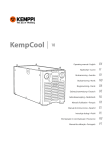
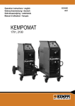
Operation instructions english Gebrauchsanweisung deutsch Gebruiksaanwijzing nederlands Manuel dutilisation français 1910010E 0244 CONTENTS 1. INTRODUCTION .............................................................................3 1.1. For the reader ...........................................................................3 1.2. Product presentation ................................................................3 1.3. Safety precautions ...................................................................3 2. BEFORE YOU START USING THE UNIT ....................................... 4 2.1. Unpacking ................................................................................ 4 2.2. Placing the unit ......................................................................... 4 2.3. Serial number ........................................................................... 4 2.4. Main components of the unit ..................................................... 5 2.5. Connecting to power supply mains .......................................... 5 2.6. Filler materials and equipment ................................................ 5 3. USE .................................................................................................. 6 3.1. Welding processes ................................................................... 6 3.1.1. Manual Metal arc welding ..................................................... 6 3.1.2. TIG welding ........................................................................... 6 3.2. Operating functions .................................................................. 6 3.3. Welding selections .................................................................... 6 3.3.1. Manual Metal arc welding (MMA) .......................................... 6 3.3.2. TIG welding ........................................................................... 7 3.4. Welding selections .................................................................. 7 3.4.1. Earth ...................................................................................... 7 3.4.2. Welding ................................................................................. 7 3.5. Storing ..................................................................................... 7 4. MAINTENANCE ............................................................................... 7 4.1. Daily maintenance .................................................................... 8 4.2. Ordering numbers ................................................................... 8 4.3. Troubleshooting ....................................................................... 8 5. TECHNICAL INFORMATION / GUARANTEE CLAUSES ................ 9 5.1. Technical information ............................................................... 9 5.2. Guarantee clauses .................................................................. 10 2 – Minarc/0244 © COPYRIGHT KEMPPI OY 1. INTRODUCTION 1.1. FOR THE READER Congratulations on having purchased a KEMPPI product. Properly installed and used KEMPPI products should prove to be productive machines requiring only a small amount of regular maintenance. This manual is arranged to give you a good understanding of the equipment and its safe use. There is also information on both servicing the unit and its technical information in the end of the booklet. Read the instructions before taking the machine into use or servicing it for the first time. Additional information on Kemppi products and their use can be obtained from Kemppi or a Kemppi dealer. Kemppi reserves the right to make changes in technical data, printed on these instructions. In this document, where ever there exists a danger to life or injury the following symbol is used: Read the warnings carefully and follow the instructions. Please also study the operation safety instructions and respect them when installing, operating and servicing the machine. 1.2. PRODUCT PRESENTATION Kemppi Minarc is a manual metal arc welding machine, small in size, suitable for industry, site and repair welding. The unit uses a one phase connection voltage and it is manufactured in two different welding power sizes 110 A and 140 A. Minarc tolerates a great fluctuation of input voltage and there-fore is thus suitable for work on sites using generator as well as to be used with long power cables. Inverter technology has been used when designing the unit. Power regulation in power source is done with IGBT transistors. Welding and earth cables are supplied with the unit. They are equipped with suitable connections for the unit electrode holder, earth clamps and connections. Minarc can also be used for TIG welding. TIG arc is started by scratching. Ordering numbers of additional equipment for TIG welding can be found in chapter 4.2. Ordering numbers. 1.3. SAFETY PRECAUTIONS Read the warning texts carefully and follow the instructions. Arc and welding spatter Arc and the reflected radiation from it can damage unprotected eyes. Shield your eyes and protect your surroundings appropriately, before you start welding. Arc and welding spatter will burn unprotected skin. When welding – use protective gloves and clothing. Danger of fire and explosion Observe the fire safety instructions. Remove flammable material near the place where you will weld. Have necessary fire extinguishing equipment at hand when you weld. Note dangers caused by special jobs, such as risk of fire and explosion when welding tanks. Note! Sparks may ignite fire even hours later! Welding is working with fire, note special instructions for such work. © COPYRIGHT KEMPPI OY Minarc/0244 – 3 Mains voltage Never take welding machine inside the piece you are working on (e.g. container or car). Never set the welding machine on wet surface. Replace faulty cables immediately, they create a danger to life and can cause a fire. See that the connecting cable does not stick nor touch sharp edges or a hot welding piece. Welding current circuit Isolate yourself from the welding current circuit by wearing dry and undamaged protective clothing. Never work on a wet surface. Never use damaged welding cables. Never set electrode holder, earth clamp nor the welding cables on top of the power source or other electric equipment. Welding fumes Ensure adequate ventilation. Always take special measures when welding metals containing lead, cadmium, zinc, mercury or beryllium. 2. BEFORE YOU START USING THE UNIT 2.1. UNPACKING The equipment is packed in durable, specially for them designed packages. Nevertheless, always before using the equipment to use, make certain it was not damaged during transportation. Also check that you have received, what you ordered and that there are instructions for it. NOTE the packaging material of the products is suitable for recycling. 2.2. PLACING THE UNIT Place the unit on level, solid and clean surface. Shield it from heavy rain and scorching sun. Make certain cooling air circulates freely. 2.3. SERIAL NUMBER Serial number of the unit is marked on the name plate on the unit. The serial number makes it possible to trace product manufacturing series. You might need the serial number placing spare parts orders or when planning maintenance . 4 – Minarc/0244 © COPYRIGHT KEMPPI OY 2.4. MAIN COMPONENTS OF THE UNIT Connect welding cable and earth cable to their connections on the power source. Mains cable and wall plug are already installed. Parts of the unit A B C D E F G H Body of machine Main power switch and signal light Selector switch for welding process Welding current regulator Signal light for overheating Electrode holder and welding cable Earth cable and clamp Mains cable B D A C E H G F - + 2.5. CONNECTING TO POWER SUPPLY MAINS The unit has a mains cable and a wall plug. You can find fuse and cable sizes in the end of these instructions on Technical information table. 2.6. FILLER MATERIALS AND EQUIPMENT See also 2.4. Main components of the unit. You can use all electrodes intended for welding with DC. Suitable electrode sizes for the unit are listed in the end of these instructions in chapter Technical information. 1. Use welding specifications given on electrode package. 2. Check that you have selected the correct welding process, before starting to weld. 3. Check that welding cable and earth cable connections are tight. If a connection is slack, it will result in voltage drop, that will cause the connection to heat. 4. Mount the electrode firmly in holder. © COPYRIGHT KEMPPI OY Minarc/0244 – 5 3. USE It is forbidden to weld in places where is a danger of fire or explosion! 3.1. WELDING PROCESSES 3.1.1. Manual Metal arc welding (MMA) In manual metal arc (MMA) the welding filler material is melted from the electrode to the weld pool. Filler and rate of welding current is selected on basis of used electrode size and welding position. Arc forms between electrode end and welding piece. The melting electrode coating forms gas and slag, that protects the weld pool. Slag solidified over the weld is removed after welding with e.g. a chipping hammer. 3.1.2. TIG welding In DC TIG welding the arc between a non-melting tungsten electrode and the welding piece melts the welding piece, where weld pool forms. Arc and electrode are shielded by an inert shielding gas (Argon). If necessary, filler is used. Filler wire is fed into the weld pool from the outside of the arc. Filler and rate of welding current is selected on the basis of diameter of tungsten electrode and welding position in use. 3.2. OPERATING FUNCTIONS See also 2.4. Main components and 3.4. Welding selections. A A Main switch and signal light B Welding process selecting switch D C Welding current adjuster D Signal light on overheating B C Main switch and signal light When you put the main switch in position I, signal light is lit and the unit is ready for welding. Signal light is always on, when the unit is connected to the mains and the main switch is in position I. Note! Always start and stop the machine from the main switch, never use the plug as a switch! Welding process selector, MMA / TIG switch is used for selecting either MMA or TIG welding, depending on welding target. Regulating welding current Welding current rate is steplessly regulated with an adjusting potentiometer. Signal light for overheating A yellow signal light of overheating is lit, when thermostat has tripped because of the unit’s overheating. Fan will cool the unit and after the signal light goes off, the unit is again ready for welding. 3.3. WELDING SELECTIONS 3.3.1. Manual Metal arc welding (MMA) Select welding parameters based on filler manufacturer’s recommendations. 1. Select polarity (+ or -) of welding current cable and return current cable in accordance with filler. 2. Select MMA welding with the switch . 3. Select suitable welding current on adjusting potentiometer scales. 6 – Minarc/0244 © COPYRIGHT KEMPPI OY 3.3.2. DC TIG welding Select welding parameters based on filler manufacturer’s recommendations. 1. Connect TIG torch to - pole and earth cable to + pole . 2. Select TIG welding with the switch 3. Select suitable welding current on adjusting potentiometer scales. 3.4. WELDING SELECTIONS Welding fumes may be dangerous to your health, see that there is ample ventilation during welding! Never look at the arc without face shield made for arc welding! Protect yourself and your surroundings from the arc and hot spatter! 3.4.1. Earth If possible, always fix earth cable clamp directly on the welding piece. 1. Clean connection surface of earth clamp from paint and rust. 2. Connect the clamp carefully so, that contact surface is as large as possible. 3. Finally check that the clamp sits tight 3.4.2. Welding See also 3.1. Welding processes and 3.4. Welding selections. Note! It is advisable to test welding and rate of welding current first on something else than the actual welding piece. You can start welding after having made necessary selections. Arc is lit by scratching the welding piece with electrode. Length of arc is regulated by holding electrode tip a suitable distance from welding piece. Suitable arc length is usually about half the diameter of the electrode core wire. When arc is lit move the electrode slowly forwards tilting it to appr. 10-15° pulling angle. If necessary, adjust current value. Shielding gas is used in DC TIG welding. Your dealer will give you advice on choosing gas and equipment. Open the gas valve on the TTM 15V TIG torch. When gas starts to flow, arc is lit by lightly scratching welding piece with the tip of the tungsten electrode. When arc is lit, its length is regulated by holding the tip of the tungsten electrode at a suitable distance from the welding piece. Move the torch forwards from the starting point. Usually in appr. 10-15° pushing angle forwards. If necessary, regulate current rate. Stop welding by lifting the torch off the welding piece and by closing the gas valve on the torch. Note! Always fix the gas cylinder so that it stays steadily in upright position either in specially made wall rack or cylinder trolley. Always close the cylinder valve after finishing welding. 3.5. STORING Store the unit in a clean and dry place. Shield it from rain, and in temperatures exceeding 25 °C shield it from direct exposure to sun. 4. MAINTENANCE Be careful when handling electrical cables! In maintaining the unit take into consideration rate of use and the environment it is used in. When the unit is used properly and regularly serviced, you will avoid unnecessary disturbances in use and production. © COPYRIGHT KEMPPI OY Minarc/0244 – 7 4.1. DAILY MAINTENANCE Perform the following maintenance daily: Clean electrode holder and TIG torch’s gas nozzle. Replace damaged or worn parts. Check TIG torch’s electrode. Replace or sharpen, if necessary. Check tightness of welding and earth cables connections. Check condition of mains and welding cables and replace damaged cables. See that there is enough space in front and back of the unit for ventilation. 4.2. ORDERING NUMBERS Item Minarc 140 welding machine (includes earth- and welding cables) Minarc 110 welding machine (includes earth- and welding cables) Earth cable and clamp Welding cable and electrode holder Optional: TIG torch TTM15V and welding cable Ordering number 6102140 6102110 6184005 6184015 6271432 4.3. TROUBLESHOOTING Main switch signal light is not lit. Unit does not get electricity. Check mains fuses and replace when necessary. Check mains cable and plug, replace damaged parts. Unit does not weld well. Arc is uneven and goes off. Electrode gets stuck in weld pool. Check welding settings and adjust when necessary. See 3. Use. Check that earth clamp is properly fixed and that contact surface is clean and the cable is undamaged. See 3.4. Welding and 4.1. Daily maintenance. Overheat signal light is lit. The unit has overheated. See 3.2. Operating functions. Check that there is ample space in front of and back of the unit for ventilation. Check welding settings. See 3.3. Welding selections. If problems in use are not solved with above mentioned measures, contact Kemppi service. 8 – Minarc/0244 © COPYRIGHT KEMPPI OY 5. TECHNICAL INFORMATION AND GUARANTEE CLAUSES 5.1. TECHNICAL INFORMATION Connection voltage, 1 ~ phase 50/60Hz Connection capacity 35 % ED 50 % ED 100 % ED Mains cable/fuse, delayed Welding current range, Metal arc welding (MMA) Minarc 140 Minarc 110 220V-10%...240V + 6% 220V-10%...240V + 6% 140 A 100 A 2,5 mm2 S /3,3 m 16 A 110 A 80 A 1,5 mm2 S /2,0 m 13 A 10 A/20,5 V...140 A/25,6 V 10 A/20,5 V...110 A/24,4 V Electrodes, diameter Welding current control range Open-circuit voltage Open-circuit power Efficiency Power factor Ø1,5...3,25 mm stepless 85V <10 W 80% 0,60 (140A/25,5 V) Ø1,5...2,5 mm stepless 85V <10W 80% 0,60 (110A/24,4 V) Degree of protection Temperature class IP 23C B (130°C)/H (180°C) IP 23C B (130°C)/H (180°C) Range of working temperature -20...+40°C Range of storage temperature -40...+60°C Degree of protection IP23C -20...+ 40°C -40...+60°C IP23C Norms IEC 974-1 EN 50199 IEC 974-1 EN 50199 250 mm (207 mm) 4,2 kg (4,8 kg) 305 mm 123 mm 250 mm (207 mm) 4,2 kg (4,6 kg) External dimensions: length height Weight The unit fulfils CE marking demands. © COPYRIGHT KEMPPI OY Minarc/0244 – 9 5.2. GUARANTEE CLAUSES KEMPPI OY gives the machines and equipment it manufactures and sells a guarantee concerning defects in manufacturing or raw materials. Guarantee repairs can only be made by approved KEMPPI repair shop. Buyer will pay for packaging, freight and insurance. Guarantee is valid from the day of purchase. Orally given promises, not included in guarantee clauses do not bind the guarantor. Restrictions in guarantee Guarantee does not cover damage caused by natural wear, use not in accordance with the instructions, overload, carelessness, neglect of following maintenance instructions, wrong mains voltage or gas pressure, disturbances or problems in mains network, damages during transportation or storing, or caused by fire or natural fenomena. Guarantee does also not cover direct nor indirect travel expenses (day allowances, accommodation, freight etc. ). Guarantee does also not cover welding torches and their consumables, nor feed rolls and wire conduits in wire conduit units. Guarantee does not cover direct or indirect damages caused by faulty product. Guarantee expires if there are any changes made into the unit, that are not approved by the manufacturer, or if other than original spare parts are used in repair works. Guarantee expires, if repair works are performed by other than KEMPPI or authorised by KEMPPI service workshop. Guarantee period Guarantee period is 1 (one) year, the unit is used in one shift daily. If it is used in two shifts daily, guarantee period is 6 (six) months and in three daily shifts guarantee period is 4 (four) months . Making guarantee repairs Faults that need guarantee repairs must be immediately, within guarantee period, reported to KEMPPI or authorised by KEMPPI service workshop. Before starting guarantee repair, the customer must present a guarantee document filled by the seller or otherwise proof in writing, with a purchasing receipt, bill or delivery documents, that the guarantee period has not expired. The document must contain date of purchase and manufacturing number of the unit to be repaired. Parts changed in guarantee repair remain KEMPPI property. Guarantee of repaired or exchanged machine or equipment continues until the end of original guarantee period. 10 – Minarc/0244 © COPYRIGHT KEMPPI OY KEMPPI OY PL 13 FIN – 15801 LAHTI FINLAND Tel (03) 899 11 Telefax (03) 899 428 www.kemppi.com KEMPPIKONEET OY PL 13 FIN – 15801 LAHTI FINLAND Tel (03) 899 11 Telefax (03) 7348 398 e-mail: [email protected] KEMPPI SVERIGE AB Box 717 S – 194 27 UPPLANDS VÄSBY SVERIGE Tel (08) 59 078 300 Telefax (08) 59 082 394 e-mail: [email protected] KEMPPI NORGE A/S Postboks 2151, Postterminalen N – 3103 TØNSBERG NORGE Tel 33 34 60 00 Telefax 33 34 60 10 e-mail: [email protected] KEMPPI DANMARK A/S Literbuen 11 DK – 2740 SKOVLUNDE DANMARK Tel 44 941 677 Telefax 44 941 536 e-mail:[email protected] KEMPPI BENELUX B.V. Postbus 5603 NL – 4801 EA BREDA NEDERLAND Tel (076) 5717 750 Telefax (076) 5716 345 e-mail: [email protected] KEMPPI (U.K) Ltd. 4-6 Sergeants Way Elms Industrial Estate BEDFORD, MK 41 OEH ENGLAND Tel (01234) 213 581 Telefax (01234) 215 128 e-mail: [email protected] KEMPPI FRANCE S.A. S.A. au capital de 5 000 000 F. 65 Avenue de la Couronne des Prés 78681 EPONE CEDEX FRANCE Tel (01) 30 90 04 40 Telefax (01) 30 90 04 45 e-mail: [email protected] KEMPPI GmbH Otto – Hahn – Straße 14 D – 35510 BUTZBACH DEUTSCHLAND Tel (06033) 88 020 Telefax (06033) 72 528 e-mail:[email protected] KEMPPI SP. z o.o. Ul. Piłsudskiego 2 05-091 ZA¸BKI Poland Tel +48 22 781 6162 Telefax +48 22 781 6505 e-mail: [email protected] KEMPPI SWITZERLAND AG Chemin de la Colice 4 CH-1023 Crissier/ Lausanne SUISSE Tel. +41 21 6373020 Telefax +41 21 6373025 e-mail: [email protected] KEMPPI WELDING MACHINES AUSTRALIA PTY LTD P.O. Box 404 (2/58 Lancaster Street) Ingleburn NSW 2565, Australia Tel. +61-2-9605 9500 Telefax +61-2-9605 5999 e-mail: [email protected] www.kemppi.com Ver. 5