1
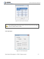
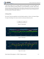
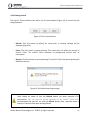
Precision Position Monitoring
mmVu® Client (Demo) User’s Manual v3.0
GEMINI
Navsoft Technologies Inc.
Knowledge Park, Suite 130
40 Crowther Lane
Fredericton, NB, Canada
E3C 0J1
www.gemini-navsoft.com
Gemini Navsoft Technologies Inc. ©2013 All rights reserved.
2
mmVu® Client (Demo) User’s Manual v3.0
Contents
1. Forward ....................................................................................................................................... 4
2. Description .................................................................................................................................. 5
2.1 Overview ............................................................................................................................... 5
2.2 System Configuration ............................................................................................................ 6
2.3 System Field Setup ................................................................................................................ 7
3. mmVu® Client Layout .................................................................................................................. 8
3.1 Ethernet TCP/IP Connection ................................................................................................. 9
3.2 TCP Data Streaming ............................................................................................................... 9
3.3 Viewing Archive Data .......................................................................................................... 10
3.4 Graphic Tools....................................................................................................................... 11
3.4.1 Baselines ....................................................................................................................... 11
3.4.2 Filter Type ..................................................................................................................... 11
3.4.3 X-Axis Control ............................................................................................................... 12
3.4.4 Y-Axis Control ............................................................................................................... 13
3.4.5 Type of Plot ................................................................................................................... 14
3.4.6 Plotting Control ............................................................................................................ 15
Gemini Navsoft Technologies Inc. ©2013 All rights reserved.
3
mmVu® Client (Demo) User’s Manual v3.0
1. Forward
Congratulations on purchasing a Gemini Navsoft Technologies’ (GNT) product. Gemini
technology is built upon years of research and developments that have allowed us to deliver the
highest level of GNSS positioning performance. This manual describes the operation of mmVu ®
3.0 Client software so that you can configure and deploy your own monitoring system.
No software can account for a prerequisite understanding of GNSS and the conditions that
optimize GNSS performance. Gemini provides supporting manuals, documentation and training
services to help you to gain this understanding. This combination of mmVu® 3.0 processing
technology and system deployment knowledge will help you to maximize the return on your
purchase.
Gemini Navsoft Technologies Inc. ©2013 All rights reserved.
4
mmVu® Client (Demo) User’s Manual v3.0
2. Description
2.1 Overview
The mmVu® Client is an independent, sub-system of mmVu® 3.0 which has been designed for
plotting mmVu® RT (e.g., mmVu® Solver, mmVu® Server and mmVu® Synergizer) real-time
Baseline solutions. The example mmVu® Client is part of the mmVu® 3.0 software package and
this manual includes instructions for system integrators who wants to use the results of the
mmVu® RT in their own software.
Gemini Navsoft Technologies Inc. ©2013 All rights reserved.
5
mmVu® Client (Demo) User’s Manual v3.0
2.2 System Configuration
mmVu® 3.0 software system is comprised of three sub-systems, including mmVu® Server,
mmVu® Engine and mmVu® Client. As illustrated in Figure 1, each mmVu® sub-system is
connected through Ethernet TCP/IP and UDP communications.
As each mmVu® sub-system runs independently, mmVu® 3.0 can be configured on either a
single hardware platform or multiple server computers. According to users’ requirements, the
system configuration of mmVu® 3.0 can be optimized.
GNSS Stations
Ethernet TCP/IP
Communications
mmVu® Server
mmVu® Client
Ethernet UDP
Communications
mmVu® Engine
Figure 1: mmVu® 3.0 system configuration
Gemini Navsoft Technologies Inc. ©2013 All rights reserved.
6
mmVu® Client (Demo) User’s Manual v3.0
2.3 System Field Setup
A typical field setup of mmVu® 3.0 is illustrated in Figure 2.
Figure 2: mmVu® 3.0 field setup
Gemini Navsoft Technologies Inc. ©2013 All rights reserved.
7
mmVu® Client (Demo) User’s Manual v3.0
3. mmVu® Client Layout
The mmVu® Client is an independent, sub-system of mmVu® 3.0 which has been designed for
plotting Baseline solutions. As plotting resources can consume CPU excessively, users are
recommended to install the mmVu® Client on their own computers rather than the Local Server
(PS100).
Users can use the mmVu® Client as a graphic viewer of the Baseline solutions (Figure 3). For
System Integrators who want to feed the Baseline solutions into their own systems, the mmVu®
Client demonstrates how this can be done (see Error! Reference source not found. and Error!
Reference source not found.).
The mmVu® Server allows a limited number of Clients to log in the GNT’s Local Server.
Figure 3: mmVu® Client layout
Gemini Navsoft Technologies Inc. ©2013 All rights reserved.
8
mmVu® Client (Demo) User’s Manual v3.0
3.1 Ethernet TCP/IP Connection
The mmVu® Client communicates with the mmVu® Server through Ethernet TCP/IP connection
as illustrated in Figure 4. Once the connection is established (see Error! Reference source not
found.), the mmVu® Server streams Baseline solutions to the mmVu® Client.
Figure 4: Ethernet TCP/IP connection panel
− Peer IP Address: Unique Ethernet IP address of the mmVu® Server.
− Peer Port Number: Port number of the mmVu® Server for TCP connection (Valid range:
8000-8999, See mmVu® Server Manual v2.0, section 4.2.1).
− Local Port Number: Port number of the user’s computer for TCP connection (Valid range:
0-65535).
− Local IP Address: Unique Ethernet IP address of the user’s computer. It will be
automatically detected by the mmVu® Client.
− User ID / Password: User ID and Password registered for the mmVu® Server.
3.2 TCP Data Streaming
TCP Data Streaming panel displays a small part of the data packets received from the mmVu®
Server (Figure 5). The Baseline solutions processed by the mmVu® Engine are encoded in
Gemini Navsoft Technologies Inc. ©2013 All rights reserved.
9
mmVu® Client (Demo) User’s Manual v3.0
packets (see Error! Reference source not found.) before the mmVu® Server streams the packets
to the mmVu® Client.
Figure 5: Data packet received by the mmVu® Client
3.3 Viewing Archive Data
The mmVu® Client allows the import of GNT format baseline solution files. This allows the user
to visualize an archive of data that can be appended and updated by the TCP data stream.
NOTE: The user should add archived data BEFORE activating the TCP Data Stream from the
Server.
Clicking the Read File button on the viewer interface brings up a browser menu (see Figure 6.)
Figure 6: Select (GNT File Format) Solution Files for visualization.
Gemini Navsoft Technologies Inc. ©2013 All rights reserved.
10
mmVu® Client (Demo) User’s Manual v3.0
Simply direct the browser to the appropriate folder location, and add the desired solution files.
For convenience, the user can import solution files for several filters and baselines from the
same folder. Different filter types for each baseline will loaded automatically. Each baseline
will be imported individually.
3.4 Graphic Tools
The mmVu® Client provides a set of graphic tools to plot the Baseline solutions. It also allows
users to analyze the charts visually.
3.4.1 Baselines
Once the mmVu® Client receives the data packet from the mmVu® Server, it starts to decode
the packet and lists up the Baselines in the packets (Figure 7). Select one Baseline to plot its
solutions. Users can switch to another Baseline any time.
Figure 7: List of Baselines
Users should be aware of that baseline switching action can cause excessive CPU
consumption. This can stop the normal operation of the mmVu® Client. It is
recommended that users click the Pause button first and then switch another
baseline, especially when a number of solutions have been already plotted.
3.4.2 Filter Type
As seen in
Gemini Navsoft Technologies Inc. ©2013 All rights reserved.
11
mmVu® Client (Demo) User’s Manual v3.0
Figure 8, users can check the TDD and DDC filter(s) to plot the Baseline solutions corresponding
to the filter(s). Uncheck the filter(s) to remove the plot corresponding to the filter(s).
Figure 8: TDD and DDC filters
3.4.3 X-Axis Control
X-Axis Control allows users to adjust the size of plot window and the frequency of plotting
(Figure 9). A maximum number of plotting points is implemented to ensure that plotting
resources do not cause excessive CPU consumption. X-Axis Control Information (Figure 10) is
shown whenever this maximum is exceeded. Adjust the display parameters to comply with the
number of plotting point’s constraint.
Figure 9: X-Axis Control panel
− Panning Window Size: The plot will be automatically panned forward when the size of
the plot displayed exceeds this input.
− Plotting Frequency: Plotting time interval in seconds.
− Update: Click this button to make an effect of the inputs in plotting.
− ?: This button will show the X-Axis Control Information as illustrated in Figure 10.
Gemini Navsoft Technologies Inc. ©2013 All rights reserved.
12
mmVu® Client (Demo) User’s Manual v3.0
Figure 10: X-Axis Control Information
Users should be aware of that all user inputs in the X-Axis Control will not be updated
unless the “Update” button is clicked.
3.4.4 Y-Axis Control
Figure 11: Y-Axis Control panel
Gemini Navsoft Technologies Inc. ©2013 All rights reserved.
13
mmVu® Client (Demo) User’s Manual v3.0
Y-Axis Control allows users to manually adjust the plotting margin of y-axis. By default, the
mmVu® Client decides the plotting margin of y-axis automatically. To activate Y-Axis Control,
move the mouse on a plotting panel (e.g., East, North or Up), press the Ctrl-key, and at the same
time click the left button of the mouse. This combination of the key actions will pop-up the YAxis Control panel as illustrated in Figure 11.
3.4.5 Type of Plot
The mmVu® Client has capabilities to plot the Baseline solutions in Point or Line feature (Figure
12, Figure 13 and Figure 14). Users can switch to another plot feature any time.
Figure 12: Type of plot
Figure 13: Point plot
Figure 14: Line plot
Gemini Navsoft Technologies Inc. ©2013 All rights reserved.
14
mmVu® Client (Demo) User’s Manual v3.0
3.4.6 Plotting Control
The mmVu® Client provides users with a set of control buttons (Figure 15) to control the plot
being displayed.
Figure 15: Plot control buttons
− Refresh: Click this button to refresh the entire plots. A warning message will be
displayed (Figure 16).
− Pause: Click this button to pause plotting. This action does not affect the process of
mmVu® Client. The mmVu® Client continues its (background) process with no
interruption.
− Resume: Click this button to resume plotting. The mmVu® Client will resume plotting the
Baselines solutions.
Figure 16: Plot Refresh warning message
Users should be aware of that the Refresh button can cause excessive CPU
consumption. This can stop the normal operation of the mmVu® Client. It is
recommended that users do not click the Refresh button often, especially when a
number of solutions have been already plotted.
Gemini Navsoft Technologies Inc. ©2013 All rights reserved.
15
mmVu® Client (Demo) User’s Manual v3.0
The mmVu® Client also provides users with a set of special key/mouse strokes to control the
plot being displayed.
− Zoon-In: Click and hold the left button of the mouse, drag forward (i.e., move the mouse
to the right direction), and then release the left button to zoon-in an area of interest.
− Zoon-Out: Click and hold the left button of the mouse, drag backward (i.e., move the
mouse to the left direction), and then release the left button to zoon-out.
− Panning: Click and hold the right button of the mouse, and drag forward or backward to
pan the plot left or right direction.
Users should be aware of that zoom or pan action can cause excessive CPU
consumption. This can stop the normal operation of the mmVu® Client. It is
recommended that users click the Pause button first and then activate the plot
controls, especially when a number of solutions have been already plotted.
Gemini Navsoft Technologies Inc. ©2013 All rights reserved.
16
mmVu® Client (Demo) User’s Manual v3.0
Document Change Record
Issue
v1.0
v2.0
v2.1
v2.1, rev2
v2.2
v3.0
Date of Release
2012-08-14
2012-10-17
2012-11-09
2013-04-04
2013-07-24
2015-02-09
Reasons for Revision
Separating Sever and Client Manuals
New version released
Baseline solution data format has been changed (see Table 4).
Revised version released
Added section 3.3 “Viewing Archive Data.”
GNT data format and communication protocol removed.
Gemini Navsoft Technologies Inc. ©2013 All rights reserved.
17