1
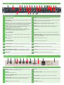
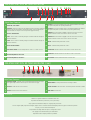
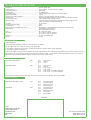
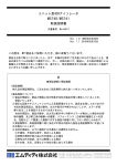
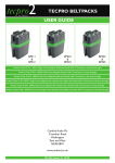
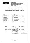
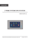
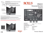
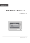
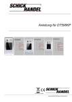
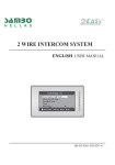
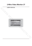
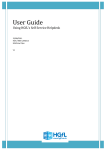
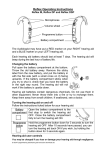
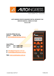
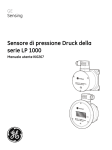
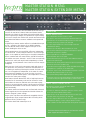
MASTER STATION MS741
MASTER STATION EXTENDER ME742
Developed from the UK’s most successful wired intercom system, the all new Series 2 Master Station and Master Station
Extender unit inherit the sturdiness and excellent build quality
of the original Tecpro designs, incorporated into a space saving
1U format. Despite the reduced size, several new features have
been added that address common installation and operational
issues.
Original Tecpro master stations offered a creditable 650mA per
circuit – enough to drive sixteen of our BP111 beltpacks.
The new MS741 master station supplies 1.25A per circuit –
almost doubling the drive current.
Like its predecessors, the new MS741 offers two independent
circuits A and B. Circuit B may be linked to A to form a single
‘super’ circuit capable of powering up to sixty BP111 beltpacks!
When combined with the master station, the ME742 extender
unit adds an extra two channels, C and D. These are technically
identical to A and B and may be used independently or linked
as required. In total, between 1 and 4 intercom circuits may be
configured.
Each intercom circuit has its own power supply with short-circuit protection. All protection is electronic and automatic so
no resetting is necessary following the removal of a fault condition. As the supplies are independent, in the event of a cable
fault temporarily disabling one circuit, the other circuit will
continue to operate uninterrupted. Over-temperature circuitry
monitors the entire power supply.
New features include ‘Remote Mic Kill’ to help keep intercom
channels free of unnecessary noise and an ‘Announce’ mode
which allows the intercom talk-back mic to be used to page
directly to an external audio system. Latching and non-latching
modes have been added to some selector switches to increase
their functionality.
The master station and extender unit are fitted with Universal
Power Supplies and can be operated world-wide without the
need to change AC power settings.
Tecpro series 2 products are backwards compatible with the
original Tecpro range (except ‘Remote Mic Kill’ facility which
applies to series 2 products only).
For further details visit www.tecpro.co.uk
Features
Master Station MS741
Two independent intercom circuits, A and B
(increases to four when combined with ME742 Extender unit)
Separate short circuit and overload protection on each circuit.
Thermal monitoring / protection for main PSU
Circuit B may be linked to A to form a single circuit with
doubled drive capacity
Supports up to 30 Tecpro BP111 beltpacks per circuit
Buit-in electret talk back microphone. XLR4 Input for optional
gooseneck microphone or headset
Built-in high efficiency 2” elliptical loudspeaker.
External speaker jack on rear panel
Additional 6.35mm jack input on rear offers additional external
dynamic microphone input
‘Remote Mic Kill’ facility will shut down all open microphones on a
selected circuit (series 2 products only)
‘Override’ function triggers Tecpro LS200 and LS300 series paging
loudspeakers to operate at pre-set audio levels
XLR3 AUX input on rear with selectable microphone or line level.
Switched 48V phantom power on mic circuit
Microphone limiting prevents signal overload
‘Announce’ output on rear allows paging to an external PA system.
This function may be triggered externally by contact closure
Master Station Extender ME742
Designed to integrate with MS741 Master Station.
Not for stand-alone operation
Provides two additional independent intercom circuits, C and D,
when operated with MS741 Master Station
Separate short circuit and overload protection on each circuit.
Thermal monitoring / protection for main PSU
Circuit D may be linked to Circuit C to form a single circuit with
doubled drive capacity. Circuit C may be linked to circuit A
Links to MS741 via cable terminated with 15-way, D-Sub connectors
The Master Station and Extender unit are fitted with Universal
Power Supplies 90-260V AC, 50-60 Hz
MASTER STATION MS741
1
2
3
4
5
6
26
7
8
25
24
9
23
10
11
12
13 14 15 16 17
18
19
20
22 21
Front Panel Features
1
Power ON / OFF Switch
14
Cancel A - Front panel accessible preset to help elliminate feedback when talkback
microphone and speaker are operating simultaneously.
2
Elliptical Speaker - High efficiency elliptical speaker provides intelligible monitoring
of the intercom circuits.
15
Cancel B - Front panel accessible preset to help elliminate feedback when talkback
microphone and speaker are operating simultaneously.
3
Announce - Routes the output from the talkback microphone directly to a dedicated
socket on the rear panel to feed an external audio system. Announce signal appears
only on Master Station rear output. Announce may also be triggered remotely.
16
Sidetone A - When a headset is plugged in, the level of the user’s voice can be
adjusted in relation to other user’s voices on intercom circuit level.
4
Override - Triggers Tecpro LS200 and LS300 series paging loudspeaker to operate at
a preset level - independent of where the loudspeaker volume has been set.
This ensures important announcements are heard.
17
Sidetone B - When a headset is plugged in, the level of the user’s voice can be
adjusted in relation to other user’s voices on intercom circuit signal level.
5
Remote Mic Kill - Shuts down all open microphones on a selected circuit.
This feature is not compatible with original Tecpro designs which use mechanical switches.
All Series 2 products use electronic switching and will respond to ‘RMK’
18
Phones Level
6
Circuit A Select Button
19
Mic - Switches talkback microphone on and off. Latching and non-latching modes.
7
Call A - When Circuit A is selected, pressing the Call button makes all Call lights on
that circuit illuminate.
20
Headset Input / Output - Inserting a gooseneck microphone automatically mutes
the Master Station’s internal microphone. Plugging in a headset mutes both the internal
microphone and the loudspeaker.
8
Call B - When Circuit B is selected, pressing the Call button makes all Call lights on
that circuit illuminate.
21
B - Indicates auxiliary selected for circuit B.
9
Circuit B Select Button
22
A - Indicates auxiliary selected for circuit A.
10
Aux Selector Switch - Directs auxiliary audio to circuit A, B, A and B or none,
23
Overload B - Indicates excessive current draw on circuit B intercom line.
11
Aux Level Control - Controls the level of the auxiliary signal.
24
Termination Off - Indicates audio termination is disabled.
12
Circuits Independent / Link B to A - Using the toggle switch, circuit B may be
linked to circuit A to form a single ‘super’ circuit with double the drive capacity .
25
Overload A - Indicates excessive current draw on circuit A intercom line.
13
Speaker Level
26
Front Panel - Brushed, anodised aluminium curved extrusion.
MASTER STATION MS741 (rear)
1
2
3
4
5
6
7
8
9
10
11
12
Rear Panel Features
1
Mic Input - Additional 3-pole A gauge 6.35mm jack for unbalanced low impedance
microphone. Phantom power not available on this input.
7
+
8
Circuit A - XLR3 intercom circuit connectors.
2
Aux Input
Balanced XLR3 auxiliary audio input.
9
Master Station Extender - 15-way D-SUB connector for linking to ME742.
3
Auxiliary mic / line selector switch - Three position switch: LINE, MIC and MIC
with +48V phantom power.
10
Speaker Output - 2-pole A gauge 6.35mm socket for 8 ohm 2W speaker.
4
Announce Output - 6-pin DIN socket. Carries balanced line level announce signal.
Also supplies relay contact for GPI and input for remote announce trigger.
11
Power Connector - IEC fused inlet for world-wide operation. 90-260 VAC, 50-60Hz.
5+
6
Circuit B - XLR3 intercom circuit connectors.
12
Rear Panel - Alocrom finish.
MASTER STATION EXTENDER ME742
1
2
3
18
4
5
17
6
16
7
8
9
10 11 12 13
15 14
Front Panel Features
1
Power ON / OFF Switch
10
Cancel C - Front panel accessible preset to help elliminate feedback when talkback
microphone and speaker are operating simultaneously.
2
Announce - Routes the output from the talkback microphone directly to a dedicated
socket on the rear panel to feed an external audio system. Announce signal appears
only on Extender rear output. Announce may also be triggered remotely.
11
Cancel D - Front panel accessible preset to help elliminate feedback when talkback
microphone and speaker (on master station) are operating simultaneously.
3
Circuit C Select Button
12
Sidetone C - When a headset is plugged in, the level of the user’s voice can be
adjusted in relation to other user’s voices on intercom circuit level.
4
Call C - When Circuit C is selected, pressing the Call button makes all Call lights on
that circuit illuminate.
13
Sidetone D - When a headset is plugged in, the level of the user’s voice can be
adjusted in relation to other user’s voices on intercom circuit level.
5
Call D - When Circuit D is selected, pressing the Call button makes all Call lights on
that circuit illuminate.
14
Aux D - Indicates auxiliary selected for circuit D.
6
Circuit D Select Button
15
Aux C - Indicates auxiliary selected for circuit C.
7
Aux Selector Switch - Directs auxiliary audio to circuit C, D, C and D or none.
16
Overload D - Indicates excessive current draw on circuit D intercom line.
8
Circuits Independent / Link C to A
17
Overload C - Indicates excessive current draw on circuit C intercom line.
9
Circuits Independent / Link D to C
18
Front Panel - Brushed, anodised aluminium curved extrusion.
MASTER STATION EXTENDER ME742 (rear)
1
2
3
4
5
6
7
8
Rear Panel Features
1
Announce Output - 6-pin DIN socket. Carries balanced line level announce signal.
Also supplies relay contact for GPI and input for remote announce trigger.
6
Master Station - 15-way D-SUB connector for linking to ME741.
2+
3
Circuit D - XLR3 intercom circuit connectors.
7
Power Connector - IEC fused inlet for world-wide operation. 90-260 VAC, 50-60Hz.
4+
5
Circuit C - XLR3 inercom circuit connectors.
8
Rear Panel - Alocrom finish.
The small print..........
TECPRO is a registered trademark of CANFORD AUDIO PLC
All products manufactured by Canford carry a two year warranty
Tecpro products are manufactured subject to stringent quality control tests.
The use of highest quality components throughout, together with our renowned mechanical build quality ensure many years of trouble free operation.
Our policy is one of continuous development.
All specifications and design details are subject to change without notice.
The copyright in this document belongs to Canford Audio.
Reproduction without express permission is prohibited.
TECHNICAL SPECIFICATION
Microphone....................................................................................................................
Headset earphone......................................................................................................
Front panel built-in mic...........................................................................................
Internal speaker...........................................................................................................
Rear speaker output..................................................................................................
System output voltage..............................................................................................
System line termination impedance...................................................................
Auxiliary Input..............................................................................................................
Rear microphone Input...........................................................................................
Announce output........................................................................................................
Call signal........................................................................................................................
Remote mic kill signal (RMK)...............................................................................
Override signal.............................................................................................................
Maximum number of outstations per circuit................................................
System cabling..............................................................................................................
Power................................................................................................................................
Fuse rating.....................................................................................................................
Dimensions....................................................................................................................
Weight.............................................................................................................................
200 ohm dynamic type
400 ohm typical – 32 ohm to 4k ohm acceptable
Electret type
2W elliptical type
2-pole A-gauge 6.35mm socket for an 8 ohm 2W speaker
+24V DC
200 ohm in the audio frequency band, 5k ohm at DC
XLR3 electronically balanced, line or mic sensitivity with +48V phantom power
2-pole A-gauge 6.35mm unbalanced socket
6-pole DIN socket with electronically balanced audio output. Single pole relay
contact rated at 30V 1A maximum for GPI use
DC and 20kHz
24kHz
28kHz
30 beltpacks or 7 loudspeaker stations (depending on model selected)
Fixed installations:31-050 FST-HD
Mobile facilities:30-130 HST-HD
90 – 260V AC50 – 60Hz
2A (T) HBC for 240V AC operation
4A (T) HBC for 110V AC operation
1U rack mount 195mm deep
1.6 kilos
WIRING CONVENTION
Cable requirements
Three factors affect the choice of cable for a particular system or installation:
(a) The length of cable run – longer runs require a larger gauge cable.
(b) The number of outstations on each cable – increasing the number of outstations requires a larger gauge cable.
(c) Permanent installation or mobile use.
In general, we suggest a screened 0.5 sq mm (20AWG) twisted pair cable should be used. Canford heavy duty cables FST-HD, HST-HD and HST-HD-R are suitable. HST-HD-R has a polyurethane jacket, which has very similar properties to rubber – i.e. very abrasion resistant and resilient. FST-HD is a foil screened
cable specifically for permanent installation purposes. HST-HD can be used for mobile systems.
SYSTEM CABLE CONNECTORS
BP111, BP112, BP114, BP116
XLR3
Pin 1
Pin 2
Pin 3
Earth / Screen
+24V DC
Audio
BP113, BP115, BP117
XLR6
Pin 1
Pin 2
Pin 3
Pin 4
Pin 5
Pin 6
Earth / Screen
+24V DC
Audio Circuit 1
Audio Circuit 2
Audio Circuit 3 - Unused for beltpacks
Audio Circuit 4 - Unused for beltpacks
N.B. XLR6 pin connectors must be Neutrik type. Switchcraft XLR6 pin types are non-standard - and are NOT suitable.
HEADSET CONNECTORS
BP111, BP112, BP113, BP114, BP115
XLR4
Pin
Pin
Pin
Pin
1
2
3
4
Microphone screen
Microphone signal
Earphones common
Earphones signal
BP116, BP117
XLR5
Pin
Pin
Pin
Pin
Pin
1
2
3
4
5
Microphone screen
Microphone signal
Earphones common
Left earphone
Right earphone
DEALER
Issue 1
CANFORD AUDIO PLC
CROWTHER ROAD
WASHINGTON
NE38 0BW
UK
tel: +44 (0) 191 418 1040
[email protected]
www.canford.co.uk