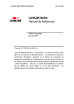
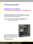
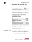
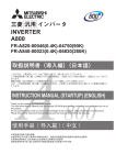
1
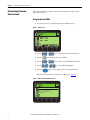
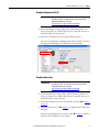
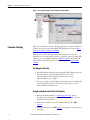
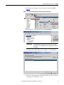
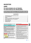
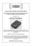
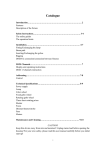
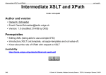
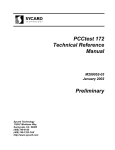
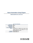
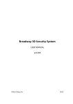
Release Notes
PowerFlex® 755 Drives (revision 3.005)
These release notes correspond to major revision 3, minor revision 5 of firmware
for PowerFlex 755 drives.
Introduction
The following information is included in this document:
For information about:
Determining Firmware Revision Level
Using the Drive LCD HIM
Using DriveExplorer Lite/Full
Using DriveExecutive
Firmware Flashing
Installing the Flash Kit
Using DriveExplorer Lite/Full to Flash Update
Using DriveExecutive to Flash Update
Using ControlFLASH to Flash Update
Using HyperTerminal to Flash Update
Enhancements
Corrected Anomalies
Know Anomalies
Restrictions and Compatible Revisions
Rockwell Automation Support
See page:
2
2
3
3
4
4
4
6
8
10
15
18
23
24
25
Chapter 1
PowerFlex® 755 Drives (revision 3.005)
Determining Firmware
Revision Level
This section describes procedures to determine the firmware revision of your
PowerFlex 755 drive.
Using the Drive LCD HIM
1. Access the Status screen, which is displayed on HIM power up.
Figure 1 - Status Screen
Host Drive
480V 2.1A
20G...D2P1
2. Use the
3. Press the
4. Use the
or
key to scroll to Port 00 for the Host Drive.
key to display its last-viewed folder.
or
key to scroll to the DIAGNOSTIC folder.
5. Use the
or
key to select Device Version.
6. Press the
(Enter) key to display device version information.
FW Revision is listed under –Main Control Board; see Figure 2.
Figure 2 - Device Version Information Screen
PowerFlex 755 480V 2.1A
Product Series
Product Revision
Product Serial Number
– Main Control Board
FW Revision
2
A
2.003
SN
2.003
Rockwell Automation Publication 750-RN019D-EN-P – November 2014
PowerFlex® 755 Drives (revision 3.005)
Chapter 1
Using DriveExplorer Lite/Full
IMPORTANT
You need DriveExplorer version 6.01 or later to interface with the
PowerFlex 755 drive. To obtain the latest version, visit the AllenBradley Web Updates site located at
http://www.ab.com/support/abdrives/webupdate.
1. Launch DriveExplorer and go online with the PowerFlex 755 drive. To
connect to the drive, use a 1203-USB converter, a 1203-SSS converter, or
an EtherNet/IP network connection.
2. In the Devices hardware view, select the PowerFlex 755 drive.
Once selected, information regarding the PowerFlex 755 drive is shown in
the right panel including the current firmware revision number.
Using DriveExecutive
IMPORTANT
You need DriveExecutive version 5.01 or later to interface with the
PowerFlex 755 drive. To obtain the latest version, visit the AllenBradley Web Updates site located at
http://www.ab.com/support/abdrives/webupdate.
1. Launch DriveExecutive and go online with the PowerFlex 755 drive. To
connect to the drive, use a 1203-USB converter, a 1203-SSS converter, or
an EtherNet/IP network connection.
2. In the Drives hardware view, select the PowerFlex 755 drive ( in Figure 3
on page 4).
3. Click the information icon ( in Figure 3) to display the drive’s Properties
dialog box.
In the Properties dialog box the “Revision:” field ( in Figure 3) will show
the drive’s current firmware revision number.
Rockwell Automation Publication 750-RN019D-EN-P – November 2014
3
Chapter 1
PowerFlex® 755 Drives (revision 3.005)
Figure 3 - Accessing the PowerFlex 755 Drive Firmware Revision Number
Firmware Flashing
This section describes procedures to flash upgrade your drive firmware. Flash kits
for drives are provided on the Allen-Bradley Web Updates site located at http://
www.ab.com/support/abdrives/webupdate.
Flashing can be performed using a 1203-USB or 1203-SSS converter. For
information on connecting either converter to your drive, refer to the 1203-USB
USB Converter User Manual, publication DRIVES-UM001 or the 1203-SSS
Smart Self-powered Serial Converter User Manual, publication 20COMMUM001.
Installing the Flash Kit
1. Install the flash kit utility from the Allen-Bradley Web Updates site for the
PowerFlex 755 drive, which includes the latest version of the
ControlFLASH utility and deploys firmware files for using
HyperTerminal on your computer.
2. You are now ready to use DriveExplorer, DriveExecutive, ControlFLASH
or HyperTerminal to update the drive. Refer to the respective section
below and follow the instructions.
Using DriveExplorer Lite/Full to Flash Update
1. With the Flash Kit installed (see Installing the Flash Kit), launch
DriveExecutive and go online (via a 1203-USB or 1203-SSS converter)
with the PowerFlex 755 drive.
2. In the Devices hardware view, select the PowerFlex 755 drive ( in
Figure 4).
3. Click the information icon ( in Figure 4) to display the drive’s Properties
dialog box.
4
Rockwell Automation Publication 750-RN019D-EN-P – November 2014
PowerFlex® 755 Drives (revision 3.005)
Chapter 1
4. In the Properties dialog box, click the Component Details tab ( in
Figure 4).
Figure 4 - Accessing the Component Details Tab of the Properties Dialog Box
5. With the Main Control Board selected, click Flash Update.
IMPORTANT
Flash updating the device firmware may cause the device to load
defaults. It is recommended that you save the setting to your PC before
proceeding.
6. From the list of available updates, select “v3.005.xxx” and click Next >.
7. Follow the remaining prompts until the flash update procedure completes
and displays the new firmware revision.
Rockwell Automation Publication 750-RN019D-EN-P – November 2014
5
Chapter 1
PowerFlex® 755 Drives (revision 3.005)
Using DriveExecutive to Flash Update
1. With the Flash Kit installed (see Installing the Flash Kit), launch
DriveExecutive and go online (via a 1203-USB or 1203-SSS converter)
with the PowerFlex 755 drive.
2. In the Drives hardware view, select the PowerFlex 755 drive ( in Figure 3
on page 4).
3. Click the information icon ( in Figure 3) to display the drive’s Properties
dialog box.
4. In the Properties dialog box, click the Component Details tab ( in
Figure 3).
5. With the PowerFlex 755 drive selected, click Flash Update.
6. From the list of available devices, select the PowerFlex 755 drive and click
Next >.
IMPORTANT
6
Flash updating the device firmware may cause the device to load
defaults. It is recommended that you save the setting to your PC before
proceeding.
Rockwell Automation Publication 750-RN019D-EN-P – November 2014
PowerFlex® 755 Drives (revision 3.005)
Chapter 1
7. From the list of available updates, select “v3.005.xxx” and click Next >.
8. Follow the remaining screen prompts until the flash update procedure
completes and displays the new firmware revision.
Rockwell Automation Publication 750-RN019D-EN-P – November 2014
7
Chapter 1
PowerFlex® 755 Drives (revision 3.005)
Using ControlFLASH to Flash Update
1. With the Flash Kit installed (see Installing the Flash Kit on page 4), launch
ControlFLASH by selecting Start > (All) Programs > Flash
Programming Tools > ControlFLASH.
2. On the ControlFLASH Welcome screen, click Next >.
3. The Catalog Number dialog box appears. From the list, choose the
communication device you will use to update the PowerFlex 755 drive. In
the figure below, the embedded EtherNet device is selected.
Once the appropriate communication device is selected, click Next >.
8
Rockwell Automation Publication 750-RN019D-EN-P – November 2014
PowerFlex® 755 Drives (revision 3.005)
Chapter 1
4. Now that the correct communication device has been selected, you must
select which device is being updated. With the Select the PowerFlex…
dialog box displayed, follow these steps.
a. Expand the hardware view for the communication path you are using
( in Figure 5).
b. Select the drive icon that represents the PowerFlex 755 drive you are
updating ( in Figure 5).
c. Click OK ( in Figure 5).
Figure 5 - Selecting the Correct Drive to Flash
5. In the Multiple Assemblies Found display box, select
“Port x-PowerFlex 755” from the list and click OK.
Rockwell Automation Publication 750-RN019D-EN-P – November 2014
9
Chapter 1
PowerFlex® 755 Drives (revision 3.005)
6. In the Firmware Revision dialog box, select “v3.005…” from the list of
available updates and click Next >.
7. Follow the remaining prompts until the flash procedure completes and
displays the new firmware revision.
Using HyperTerminal to Flash Update
Important: The HyperTerminal process takes at least one hour to
complete.
1. With the Flash Kit installed (see Installing the Flash Kit on page 4), access
and launch HyperTerminal as shown below.
10
Rockwell Automation Publication 750-RN019D-EN-P – November 2014
PowerFlex® 755 Drives (revision 3.005)
Chapter 1
2. A New Connection dialog box appears.
a. Enter the connection device name in the Name field or select an icon
from the library.
b. Click OK once you have finished.
3. A Connect To dialog box appears,
a. Use the “Connect using:” drop-down menu to select the appropriate
connection device.
b. Click OK once you have finished.
Rockwell Automation Publication 750-RN019D-EN-P – November 2014
11
Chapter 1
PowerFlex® 755 Drives (revision 3.005)
4. A Properties dialog box will appear for the selected connection device.
a. Use any of the drop-down menus to change the various port settings.
b. Click OK once you have finished.
5. After you click OK, you will get a blank screen.
Press Enter on your computer keyboard so the following test screen
appears.
6. From the Main Menu, select the flash upgrade ( in Figure 6) by pressing
the number 3 key on your computer keyboard.
7. Additonal text appears. From the Flash Upgrade menu, select the
PowerFlex 775 drive ( in Figure 6) by pressing the number 0 key on your
computer keyboard.
8. Additonal text appears. After reading the conditions, select Yes ( in
Figure 6) to proceed by pressing the letter Y key on your computer
keyboard.
12
Rockwell Automation Publication 750-RN019D-EN-P – November 2014
PowerFlex® 755 Drives (revision 3.005)
Chapter 1
Figure 6 - HyperTerminal Test Screen Dialogue
The terminal program will start displaying the letter “C”. This signals the
XMODEM protocol that the download may proceed.
IMPORTANT
TIP
You have one minute to complete steps 9…14 or HyperTerminal will
return to step 5, where you must repeat steps 5…8.
To cancel the flash update at any time, press CTRL-X.
9. Select Transfer > Send File to display the Send File dialog box.
10. Click Browse and navigate to one of the following locations:
• For PowerFlex 755 drive frames 2…7, go to
C: > Program Files > ControlFLASH > 0001 > 0086 > 0890
• For PowerFlex 755 drive frames 8 and larger, go to
C: > Program Files > ControlFLASH > 0001 > 0086 > 0C90
Rockwell Automation Publication 750-RN019D-EN-P – November 2014
13
Chapter 1
PowerFlex® 755 Drives (revision 3.005)
11. Search within the appropriate subfolder until the
“PF755_LP_App_v3_005_xxx.dpi” file appears in the Select File to Send
list.
12. With the file name highlighted, click Open so it appears in the Filename
data field in the Send File dialog box.
13. In the Protocol box, select “Xmodem.”
14. Click Send.
A dialog box appears and reports the update progress, which takes about
one hour for HyperTerminal to complete. When it is complete, the
message “Flash Complete” appears.
15. Press any key to continue.
16. Press the Enter key to return to the main menu.
14
Rockwell Automation Publication 750-RN019D-EN-P – November 2014
PowerFlex® 755 Drives (revision 3.005)
Chapter 1
This section describes the enhancements in this revision.
Enhancements
Additional Voltage and Current Ratings
The following ratings have been added to the Frame Rating Tables in this revision
of firmware:
PWM Frequency Voltage
2 kHz
480V
400V
4 kHz
480V
400V
Code
D800
D960
D1K0
D1K2
D1K3
D1K4
C910
C1K0
C1K1
C1K2
C1K4
C1K5
D840
D950
D1K0
D1K2
D1K3
D1K4
C900
C1K0
C1K1
C1K2
C1K4
C1K5
LD Current (A)
960
1045
1135
1365
1420
1540
1040
1090
1175
1465
1480
1600
LD Power (Hp)
800
900
1000
1100
1250
1350
560
630
710
800
850
900
700
790
855
1030
1110
1160
785
850
885
1090
1155
1205
ND Current (A)
800
960
1045
1135
1365
1420
910
1040
1090
1175
1465
1480
ND Power (Hp)
700
800
900
1000
1100
1250
500
560
630
710
800
850
625
700
790
895
1030
1075
665
785
825
945
1090
1115
HD Current (A)
710
795
800
960
1045
1135
750
880
910
1040
1090
1175
HD Power (Hp)
600
700
750
800
900
1000
400
500
500
560
630
710
540
600
660
700
790
895
555
660
685
785
845
930
Parallel Power Structures
This revision of firmware adds features that accommodate the use of parallel
power structures. These features allow for the operation of the drive while one
power structure is disconnected, and for the rerating of the drive as power
structures are added or subtracted.
Flying Start - Frequency Search for Frames 2…7
This revision of firmware adds the Sweep (Frequency Search) mode to Flying
Start. This mode is helpful for applications with multiple motors per drive and
applications with filters between the drive and motor.
Select this mode by placing a value of 2 - “Sweep” in parameter 356 [FlyingStart
Mode].
Rockwell Automation Publication 750-RN019D-EN-P – November 2014
15
Chapter 1
PowerFlex® 755 Drives (revision 3.005)
Interior Permanent Magnet (IPM) Motor with Feedback
This revision of firmware adds the ability to control an Interior Permanent
Magnet (IPM) motor. This control requires the use of motor speed or position
feedback device and feedback option module, such as the single encoder module
(20-750-ENC-1) dual encoder module (20-750-DENC-1) or universal feedback
board (20-750-UFB-1).
Select this control mode by selecting a value of 10 - “IPM FV” in parameter 35
[Motor Ctrl Mode].
Adjustable Voltage Boost
This revision of firmware adds the Adjustable Voltage Boost feature. This feature
is useful for starting high torque motors in the volts per hertz control mode.
Use this feature by configuring parameters 1131 [AdjVltgConfig] through 1152
[Min Adj Voltage].
Auto/Manual HIM Preload
This revision of firmware adds the ability to configure the drive to switch
smoothly from an automatic (communicated) speed reference to manual speed
reference produced by the Human Interface Module (HIM). When the drive is
commanded to switch from the automatic (communicated) speed reference to
the manual reference via a digital input, it preloads the last value from the speed
feedback into the HIM. Then the operator can modify the manual reference on
the HIM. This avoids a step change in speed that would otherwise occur from the
switch.
Use this feature by configuring parameters 328 [Alt Man Ref Sel], 331 [Manual
Preload], 172 [DI Manual Ctrl], and 563 [DI ManRefSel].
This feature requires revision 1.008 of HIM firmware or later.
Stop Dwell
This revision of firmware adds the stop dwell feature, which sets an adjustable
delay time between detecting zero speed and disabling the speed and torque
regulators, when responding to a stop command.
Use this feature by configuring parameter, 392 [Stop Dwell Time]. The value of
this parameter defines the dwell time in seconds.
16
Rockwell Automation Publication 750-RN019D-EN-P – November 2014
PowerFlex® 755 Drives (revision 3.005)
Chapter 1
Customer Configurable Response to HIM Communications Loss
This revision of firmware adds an enhancement that allows customers to
configure the drive’s response to a HIM DPI communication loss on DPI ports 1
through 3. The configuration options are similar to those for communication
faults on network communications adapters.
Use this feature by configuring parameters 865 [DPI Pt1 Flt Actn] through 867
[DPI Pt3 Flt Actn] and 868 [DPI Pt1 Flt Ref ] through 870 [DPI Pt3 Flt Ref ].
This feature requires a new enhanced style HIM (20-HIM-A6, 20-HIM-C6S).
This feature will not work with older contemporary 7-Class HIM's (20-HIMA3, 20-HIM-A5, 20-HIM-C3S, 20-HIM-C5S).
Initial MOP Values
This revision of firmware adds an enhancement to the MOP functionality that
makes it possible for customers to configure the MOP to have an initial value
other than the last value saved “At Power Down” or “At Stop.”
Use this feature by configuring parameter 566 [MOP Init Select] and 567 [MOP
InitStpt].
Hand-Off-Auto Start
This revision of firmware adds a new digital input function that allows for handoff-auto control. It functions like a three-wire start signal; with the exception,
that it does not require the DI Stop to be high for a full input cycle before the
drive looks for a rising edge on DI HOA Start.
Use this feature by configuring parameter 176 [DI HOA Start].
Test Voltage Pulse Width Adjustment for PM Offset Test
This revision of firmware contains an enhancement, to the Static Encoder Offset
Test in the Autotune procedure for surface mount permanent magnet motors.
The test accommodates longer voltage pulse widths.
Rockwell Automation Publication 750-RN019D-EN-P – November 2014
17
Chapter 1
PowerFlex® 755 Drives (revision 3.005)
Corrected Anomalies
This section describes the anomalies corrected in this revision.
Drive Status Data in CIP Motion Mode
Updates to some drive information data did not reach the controller under
certain conditions. This information included the DC bus status
(AxisName.DCBusUpStatus) and the guard OK status
(AxisName.GuardOKStatus). These functions performed properly in the drive,
but the controller did not always receive status information.
Certain data is only transferred between the controller and drive when data has
changed. There is a mechanism which performs the handshaking and verification
of this data transfer between the controller and the drive. There was an issue with
this verification mechanism when there were missed messages between the drive
and the controller. This anomaly has been corrected.
Soft Reset
This anomaly existed in firmware revision 3.003, which was a pre-production
release. If the drive was using the sleep wake mode or Start on Power-up mode,
and the conditions for drive starting were present at the time of a soft reset (reset
from HIM or software); the drive would start. In previous revisions and revisions
going forward, the drive will not start until the conditions for start are removed
and re-established after soft reset is received.
Multicast Messages Cause Synch Fault
When a new node is added to an Ethernet switch (this has occurred on Stratix
8000 switch, which is recommended in the CIP Motion Reference Architecture),
the switch sends out a high volume of multicast messages and the PowerFlex 755
drives would respond with a CIP Motion Synch Fault.
Max Pole Count
The motor pole count was incorrectly limited to 20, in frame 8 drives.
18
Rockwell Automation Publication 750-RN019D-EN-P – November 2014
PowerFlex® 755 Drives (revision 3.005)
Chapter 1
Pepperl+Fuchs Linear Position Encoder and Universal Feedback
Board
The anomaly concerned the interaction with a Pepperl+Fuchs Linear Position
Encoder and the Universal Feedback Board (UFB). The Pepperl+Fuchs linear
position encoder communicates to the UFB using the Synchronous Serial
Interface (SSI). The reading head on the linear position encoder reads the code
rail and sends the position to the UFB. When the code rail is not in the reading
head, the reading head sends an out-of-rail alarm to the UFB.
When the anomaly occurred, the UFB would cease communicating with the
linear position encoder. The UFB would not re-establish communication when
the code rail entered the reading head, and the drive did not receive position
feedback data.
Three things could trigger the anomaly:
• The drive was powered up when the code rail was not in the reading
head.
• There was a command to initialize the UFB when the code rail was not in
reading head.
• Change to the value of a parameter in the UFB that can only be modified
when the drive is stopped when the code rail was not in the reading head
(this causes a command to initialize the UFB).
This would occur regardless of the settings for parameters 9 [FB0 Loss Cfg] and
39 [FB1 Loss Cfg]. Even if you configured the drive to ignore the feedback loss or
alarm in response to the feedback loss, the UFB would stop communicating to
the linear position encoder.
Revision 1.015 of UFB firmware was created to correct this anomaly.
This revision of main control board firmware is needed if your application
requires the drive to fault when the code rail is not in the reading head.
Power Structure Configuration Changes Not Detected on First Power
Cycle after Flash Update
The drive would fail to recognize configuration changes to the power structure
on the first power cycle after the drive firmware was updated. This only affected
frame 8 drives.
Rockwell Automation Publication 750-RN019D-EN-P – November 2014
19
Chapter 1
PowerFlex® 755 Drives (revision 3.005)
Incorrect Option Parameter Settings after Device Conflict Resolved
When a device conflict was found and the new device accepted, the optionaccept code did not reset option module parameter values to defaults (although it
did clear the option parameter Non Volatile Storage). If there was previously
another option module in the slot, the new option module could have nondefault values in any parameters, which had non-default values in the old option
module.
Improper Fault Code After Reset to Defaults on Ports 10 or 11
The drive would produce a fault F59 “Invalid Code” after the converter at port
11 or the inverter at port 10 was reset to defaults.
Interference between Simultaneous Non Volatile Storage (NVS)
Rebuilds
When NVS rebuilds occurred at the same time for multiple option modules there
could be interference. This could produce improper parameter values in the
option modules after a power cycle.
Non-Volatile Storage Buffers for DeviceLogix and EtherNet/IP Port
After a power cycle, some parameters related to DeviceLogix and the EtherNet/
IP port could return to their default values. This was related to the size of the
space allocated for DeviceLogix and EtherNet/IP parameters.
If you changed more DeviceLogix parameter values than the allotted space, some
of those parameter values would not be stored in NVS and would return to their
default values after a power cycle. If you downloaded a DeviceLogix
configuration file or Ethernet/IP Port configuration file containing more
parameter values than three-fourths of the allotted space, the download would
fail and some of the parameters that should have downloaded would remain at
their default values and/or return to their default values after a power cycle.
20
Rockwell Automation Publication 750-RN019D-EN-P – November 2014
PowerFlex® 755 Drives (revision 3.005)
Chapter 1
Non-Volatile Storage for I/O Option Modules and the EtherNet/IP Port
After a power cycle, some parameters related to I/O option modules and the
EtherNet/IP port could return to their default values. This was related to a
particular issue related to the addressing of NVS.
Parameters related to 115VAC I/O option modules include:6 [Dig Out Invert],
7 [Dig Out Setpoint], 10[RO0 Sel], 11 [RO0 Level Sel], 12 [RO0 Level], 14
[RO0 On Time], 15 [RO0 Off Time], 20 [RO1 Sel], 21 [RO1 Level Sel], 22
[RO1 Level], 24 [RO1 On Time], 25 [RO1 Off Time],40 [PTC Cfg], 46 [Anlg
In Sqrt], 53 [Anlg In0 LssActn], 55 [Anlg In0 FiltGn], 56 [Anlg In0 Filt BW], 63
[Anlg In1 LssActn], 65 [Anlg In1 FiltGn], 66 [Anlg In1 Filt BW], 71 [Anlg Out
Abs], 75 [Anlg Out0 Sel], 76 [Anlg Out0 Stpt], 78 [Anlg Out0 DataHi], 79
[Anlg Out0 DataLo], 85 [Anlg Out1 Sel], 86 [Anlg Out1 Stpt], 88 [Anlg Out1
DataHi], 89 [Anlg Out1 DataLo].
Parameters related to the 24V I/O option modules with transistor outputs
include: 2 [Dig In Filt Mask], 3 [Dig In Filt], 6 [Dig Out Invert], 7 [Dig Out
Setpoint], 10 [RO0 Sel], 11 [RO0 Level Sel], 12 [RO0 Level], 14 [RO0 On
Time], 15 [RO0 Off Time], 20 [RO1 Sel], 21 [RO1 Level Sel], 22 [RO1 Level],
24 [RO1 On Time], 25 [RO1 Off Time], 30 [TO1 Sel], 31 [TO1 Level Sel], 32
[TO1 Level], 34 [TO1 On Time], 35 [TO1 Off Time], 40 [PTC Cfg], 46 [Anlg
In Sqrt], 53 [Anlg In0 LssActn], 55 [Anlg In0 FiltGn], 56 [Anlg In0 Filt BW], 63
[Anlg In1 LssActn], 65 [Anlg In1 FiltGn], 66 [Anlg In1 Filt BW], 71 [Anlg Out
Abs], 75 [Anlg Out0 Sel], 76 [Anlg Out0 Stpt], 78 [Anlg Out0 DataHi], 79
[Anlg Out0 DataLo], 85 [Anlg Out1 Sel], 86 [Anlg Out1 Stpt], 88 [Anlg Out1
DataHi], 89 [Anlg Out1 DataLo].
Parameters related to the 24V I/O option modules with relay outputs include: 2
[Dig In Filt Mask], 3 [Dig In Filt], 6 [Dig Out Invert], 7 [Dig Out Setpoint], 10
[RO0 Sel], 11 [RO0 Level Sel], 12 [RO0 Level], 14 [RO0 On Time], 15 [RO0
Off Time], 20 [RO1 Sel], 21 [RO1 Level Sel], 22 [RO1 Level], 24 [RO1 On
Time], 25 [RO1 Off Time], 40 [PTC Cfg], 46 [Anlg In Sqrt], 53 [Anlg In0
LssActn], 55 [Anlg In0 FiltGn], 56 [Anlg In0 Filt BW], 63 [Anlg In1 LssActn],
65 [Anlg In1 FiltGn], 66 [Anlg In1 Filt BW], 71 [Anlg Out Abs], 75 [Anlg Out0
Sel], 76 [Anlg Out0 Stpt], 78 [Anlg Out0 DataHi], 79 [Anlg Out0 DataLo], 85
[Anlg Out1 Sel], 86 [Anlg Out1 Stpt], 88 [Anlg Out1 DataHi], 89 [Anlg Out1
DataLo].
Parameters related to the EtherNet/IP port include the datalink parameters (1
[DL From Net 01]…16 [DL From Net 16] and 17 [DL To Net 01]…32 [DL To
Net 16]).
Logic Mask Did Not Affect Start at Power Up
The Start at Power Up function, which is configured by parameter 345 [Start
AtPowerUp], would work regardless of the settings in parameter 324 [Logic
Mask].
Rockwell Automation Publication 750-RN019D-EN-P – November 2014
21
Chapter 1
PowerFlex® 755 Drives (revision 3.005)
Erroneous Fault Reporting During Autotune Test
The DriveExplorer fault queue could indicate F12 “HW Over-current” after a
reverse Autotune test. The HIM would not display the fault.
ControlFLASH Timed Out when Updating Drive
ControlFLASH would time out when updating the drive over EtherNet/IP with
a Stratix 8000 switch. However, the drive would properly apply the flash update.
Parameter 1114 [Brake Test Torq] Was Missing from File and Group
Parameter 1114 [Brake Test Torq] was missing from the Torque Prove group in
the Application parameter file in frame 8 drives. The parameter was in the
general Linear List.
Missing Error When Drive NV Selected in Integrated Motion Mode
This anomaly affected customers using Integrated Motion on EtherNet/IP (CIP
Motion). If you attempted to use Drive NV when configuring the motor on a
motion axis with a PowerFlex 755, the drive would not return the appropriate
error. This feature is not currently supported in the PowerFlex 755.
MRHD Motion Run Hookup Diagnostics
The .PC and .DN bits of a MHRD motion instruction would not behave
properly. An additional 40 ms delay was required before executing another
motion instruction.
Parameters 490 [HSFanElpsdLife] and 501 [InFanResetLog] Not
Shown
Parameters 490 [HSFanElpsdLife] and 501 [InFanResetLog] were not displayed
in frame 8 drives.
22
Rockwell Automation Publication 750-RN019D-EN-P – November 2014
PowerFlex® 755 Drives (revision 3.005)
Know Anomalies
Chapter 1
This section describes the known anomalies that are present in this revision:
Feedback Selection
The HIM startup on the PowerFlex 755 drive includes a feedback device
selection step. Depending on the option modules installed, that step may first ask
the user to choose a port, then a parameter. In some situations, the list of ports
incorrectly shows multiple copies of “Port 0 - PowerFlex 755” followed by the
feedback port/module.
The incorrect behavior happens only under the following conditions:
• It is the first time that startup feedback selection has been run since
flashing the drive.
• The feedback module is a dual encoder or UFB and no other option
modules are installed.
• A reset to defaults of the drive NVS parameters has not been performed
since the drive was last flashed.
When the incorrect port list appears, it is still possible to successfully select the
feedback module port by following one of these methods.
• Scroll past the multiple copies of Port 0 to reach the desired feedback
module.
• Press the Esc soft key to back up one screen, then select “Feedback” and
press the Enter soft key to display the port selection screen a second
time. This time the correct list will be shown.
Delta Junction Temp at Zero Speed
The protection algorithms in frame 8…9 drives create false 168 “PWM Freq
Reduced” exception events when running at zero speed. These can occur when
the drive is first energizing the motor and establishing motor flux.
Support for Changing Permanent Magnet Direction Test Current
You cannot change the level of current used during the direction test on a
permanent magnet motor while in Integrated Motion on EtherNet/IP (CIP
Motion) mode. It is set at 10%. If the system requires more than 10% to turn the
motor, it will fail to perform the test.
Rockwell Automation Publication 750-RN019D-EN-P – November 2014
23
Chapter 1
PowerFlex® 755 Drives (revision 3.005)
Restrictions and Compatible
Revisions
The following restrictions apply to this revision of firmware:
Max Output Frequency Limited to 590Hz
This revision of drive firmware places a limit on the maximum output frequency
of the drive. In previous versions of drive firmware the maximum operating
frequency of the drive was 650Hz. The new maximum output frequency limit is
590Hz. If a previous application allows for a maximum output frequency greater
than 590Hz, the drive will ramp to the command frequency set point and once it
reaches a value greater than 590Hz for a period of time greater than 16ms the
drive will trip on a Fault 31, “Over-Freq”.
Implementation of Secure Flash
With this revision of drive firmware, an encryption layer with digital signature
has been attached to the drive firmware flash file. This encryption layer will not
allow the flashing of firmware files that have not been digitally signed by
Rockwell Automation. When flashing from a revision of firmware that is not
digitally signed, users will first need to flash up to V11.001 to enable the secure
flash feature to read the digital signature. Once at V11.001, a customer can flash
to any desired firmware revision level that has a secure digital signature. Previous
versions of drive firmware that don’t have a secure digital signature embedded in
the flash file will display the error shown below when a flash is attempted.
Series A Frame 8 Drives Can Not Use Revision 3 Firmware
Revision 3.xxx is not compatible with Series A frame 8 drives.
Revision 3.xxx is compatible with Series A frame 2…7 drives and Series B frame
8…9 drives.
Auto/Manual HIM Preload Requires New HIM Firmware
The new Auto/Manual HIM Preload feature requires firmware in the HIM that
is newer than 1.007.
24
Rockwell Automation Publication 750-RN019D-EN-P – November 2014
PowerFlex® 755 Drives (revision 3.005)
Chapter 1
Customer Configurable Response to HIM Communications Loss
The Customer Configurable Response to HIM Communications Loss feature
requires a new enhanced style HIM (20-HIM-A6, 20-HIM-C6S). This feature
will not work with older contemporary 7-Class HIM’s (20-HIM-A3, 20-HIMA5, 20-HIM-C3S, 20-HIM-C5S).
Embedded EtherNet/IP Port Requires Quality of Service (QoS)
With this firmware revision, the drive’s embedded EtherNet/IP port requires the
EtherNet/IP scanner to use a compatible method of specifying Quality of Service
(QoS). The following table details the compatible products and firmware
revisions.
Product
DriveLogix 5730 Embedded Ethernet Port
CompactLogix (1769-L2x/L3x)
ControlLogix (1756-ENBT)
CompactLogix (1768-ENBT)
FlexLogix (1788-ENBT)
ControlLogix 1756-EN2T (F)(XT)
SoftLogix I/O Messaging
Rockwell Automation
Support
Compatible Rev. No.
Rev. 3.004
Rev. 17.03
Rev. 4.005
Rev. 2.001
Rev. 2.004
No Update needed
No Update needed
To assist you, Rockwell Automation provides technical information on the web.
At http://www.rockwellautomation.com/support, you can find technical
manuals, a knowledge base of Frequently Asked Questions (FAQs), technical and
application notes, sample code and links to software service packs, and a
MySupport feature you can customize to best use these tools.
If you experience a problem, please review product documentation. For further
help, contact a Customer Support representative:
United States
Outside United States
(1) 262.512.8176 • Monday – Friday, 7am – 6pm CST
Please contact your local Rockwell Automation representative for any technical
support issues.
TechConnect Support programs are available for an additional level of technical
phone support for installation, configuration, and troubleshooting. For more
information, contact your local distributor or Rockwell Automation
representative, or visit http://www.rockwellautomation.com/support.
Rockwell Automation Publication 750-RN019D-EN-P – November 2014
25
www.rockwel lautomation.com
Power, Control and Information Solutions Headquarters
Americas: Rockwell Automation, 1201 South Second Street, Milwaukee, WI 53204-2496 USA, Tel: (1) 414.382.2000, Fax: (1) 414.382.4444
Europe/Middle East/Africa: Rockwell Automation NV, Pegasus Park, De Kleetlaan 12a, 1831 Diegem, Belgium, Tel: (32) 2 663 0600, Fax: (32) 2 663 0640
Asia Pacific: Rockwell Automation, Level 14, Core F, Cyberport 3, 100 Cyberport Road, Hong Kong, Tel: (852) 2887 4788, Fax: (852) 2508 1846
Publication 750-RN019D-EN-P – November 2014
Supersedes 750-RN019B-EN-P – May 2012
Copyright © 2014 Rockwell Automation, Inc. All rights reserved. Printed in USA.