1
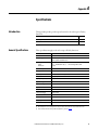
Safety Reference Manual
Kinetix 6200 and Kinetix 6500
Safe Torque-off Multi-axis Servo Drives
Catalog Numbers 2094-SE02F-M00-S0, 2094-EN02D-M01-S0
Important User Information
Solid-state equipment has operational characteristics differing from those of electromechanical equipment. Safety
Guidelines for the Application, Installation and Maintenance of Solid State Controls (publication SGI-1.1 available from
your local Rockwell Automation® sales office or online at http://www.rockwellautomation.com/literature/) describes some
important differences between solid-state equipment and hard-wired electromechanical devices. Because of this difference,
and also because of the wide variety of uses for solid-state equipment, all persons responsible for applying this equipment
must satisfy themselves that each intended application of this equipment is acceptable.
In no event will Rockwell Automation, Inc. be responsible or liable for indirect or consequential damages resulting from the
use or application of this equipment.
The examples and diagrams in this manual are included solely for illustrative purposes. Because of the many variables and
requirements associated with any particular installation, Rockwell Automation, Inc. cannot assume responsibility or
liability for actual use based on the examples and diagrams.
No patent liability is assumed by Rockwell Automation, Inc. with respect to use of information, circuits, equipment, or
software described in this manual.
Reproduction of the contents of this manual, in whole or in part, without written permission of Rockwell Automation,
Inc., is prohibited.
Throughout this manual, when necessary, we use notes to make you aware of safety considerations.
WARNING: Identifies information about practices or circumstances that can cause an explosion in a hazardous environment,
which may lead to personal injury or death, property damage, or economic loss.
ATTENTION: Identifies information about practices or circumstances that can lead to personal injury or death, property
damage, or economic loss. Attentions help you identify a hazard, avoid a hazard, and recognize the consequence.
SHOCK HAZARD: Labels may be on or inside the equipment, for example, a drive or motor, to alert people that dangerous
voltage may be present.
BURN HAZARD: Labels may be on or inside the equipment, for example, a drive or motor, to alert people that surfaces may
reach dangerous temperatures.
IMPORTANT
Identifies information that is critical for successful application and understanding of the product.
Allen-Bradley, Kinetix, RSLogix, TechConnect, Rockwell Automation, and Rockwell Software are trademarks of Rockwell Automation, Inc.
Trademarks not belonging to Rockwell Automation are property of their respective companies.
Summary of Changes
This manual contains new and updated information.
New and Updated
Information
This revision includes new material for the 2090-K6CK-D44S0 low-profile
connector kit and 2090-CS0DSDS-AAxx interface cable for cascading the safe
torque-off signals from drive-to-drive.
Section
Topic
Page
Chapter 2
Added a description and connection diagram for the 2090-K6CK-D44S0 connector kit.
16
Chapter 3
Updated Safety Input Wiring diagram to use 24VPWR (IOD-14, IOD-15)
22
Updated Cascaded Connections diagram to use 24VPWR (IOD-14, IOD-15)
27
Updated 2090-K6CK-D44M wiring examples to use 24VPWR (IOD-14, IOD-15)
28
Added 2090-K6CK-D44S0 wiring examples
29…30
Chapter 4
Added Kinetix 6200/6500 cascading safe torque-off cable example
Added 2090-CS0DSDS-AAxx cable pinout diagram and termination table
Appendix A
Updated General Specifications with value for reset time
Added footnotes to clarify the effect cascading drives has on reaction time and reset time
Rockwell Automation Publication 2094-RM002B-EN-P - May 2012
31
37
3
Summary of Changes
Notes:
4
Rockwell Automation Publication 2094-RM002B-EN-P - May 2012
Table of Contents
Preface
About This Publication. . . . . . . . . . . . . . . . . . . . . . . . . . . . . . . . . . . . . . . . . . . . . 7
Who Should Use This Manual . . . . . . . . . . . . . . . . . . . . . . . . . . . . . . . . . . . . . . 7
Terminology. . . . . . . . . . . . . . . . . . . . . . . . . . . . . . . . . . . . . . . . . . . . . . . . . . . . . . . 7
Additional Resources . . . . . . . . . . . . . . . . . . . . . . . . . . . . . . . . . . . . . . . . . . . . . . . 8
Chapter 1
Safety Concept
Introduction. . . . . . . . . . . . . . . . . . . . . . . . . . . . . . . . . . . . . . . . . . . . . . . . . . . . . . . 9
Safety Certification. . . . . . . . . . . . . . . . . . . . . . . . . . . . . . . . . . . . . . . . . . . . . . . . . 9
Important Safety Considerations . . . . . . . . . . . . . . . . . . . . . . . . . . . . . . 10
Safety Category 4 Performance Definition. . . . . . . . . . . . . . . . . . . . . . 10
Stop Category 0 Definition. . . . . . . . . . . . . . . . . . . . . . . . . . . . . . . . . . . . 10
Performance Level and Safety Integrity Level (SIL) CL3 . . . . . . . . . 11
PFD and PFH Definitions . . . . . . . . . . . . . . . . . . . . . . . . . . . . . . . . . . . . . . . . 11
PFD and PFH Data . . . . . . . . . . . . . . . . . . . . . . . . . . . . . . . . . . . . . . . . . . . . . . 11
Safe State . . . . . . . . . . . . . . . . . . . . . . . . . . . . . . . . . . . . . . . . . . . . . . . . . . . . . . . . 12
Safety Reaction Time. . . . . . . . . . . . . . . . . . . . . . . . . . . . . . . . . . . . . . . . . . . . . 12
Contact Information If Failure Occurs. . . . . . . . . . . . . . . . . . . . . . . . . . . . . 12
Automatic Drive Replacement (ADR) . . . . . . . . . . . . . . . . . . . . . . . . . . . . . 12
Chapter 2
Installation and Wiring
Introduction. . . . . . . . . . . . . . . . . . . . . . . . . . . . . . . . . . . . . . . . . . . . . . . . . . . . .
General Safety Information . . . . . . . . . . . . . . . . . . . . . . . . . . . . . . . . . . . . . . .
Power Supply Requirements . . . . . . . . . . . . . . . . . . . . . . . . . . . . . . . . . . . . . .
Wiring the Safety Connections. . . . . . . . . . . . . . . . . . . . . . . . . . . . . . . . . . . .
Using the 2090-K6CK-D44M Low-profile Connector Kit . . . . . .
Using the 2090-K6CK-D44S0 Low-profile Connector Kit . . . . . .
Using the Motion-allowed Plug. . . . . . . . . . . . . . . . . . . . . . . . . . . . . . . .
Terminal Connections . . . . . . . . . . . . . . . . . . . . . . . . . . . . . . . . . . . . . . . . . . .
13
13
14
14
14
16
17
18
Chapter 3
Safe Torque-off I/O Signals
Introduction. . . . . . . . . . . . . . . . . . . . . . . . . . . . . . . . . . . . . . . . . . . . . . . . . . . . .
Inputs. . . . . . . . . . . . . . . . . . . . . . . . . . . . . . . . . . . . . . . . . . . . . . . . . . . . . . . . . . .
Discrepancy Time . . . . . . . . . . . . . . . . . . . . . . . . . . . . . . . . . . . . . . . . . . . .
Reset Input (Reset_In). . . . . . . . . . . . . . . . . . . . . . . . . . . . . . . . . . . . . . . .
Outputs . . . . . . . . . . . . . . . . . . . . . . . . . . . . . . . . . . . . . . . . . . . . . . . . . . . . . . . . .
Safe Stop Output (SS_Out) . . . . . . . . . . . . . . . . . . . . . . . . . . . . . . . . . . .
Safe Stop Reset . . . . . . . . . . . . . . . . . . . . . . . . . . . . . . . . . . . . . . . . . . . . . . .
Safe Stop Wiring Example . . . . . . . . . . . . . . . . . . . . . . . . . . . . . . . . . . . . . . . .
Rockwell Automation Publication 2094-RM002B-EN-P - May 2012
19
19
20
23
23
23
25
26
5
Table of Contents
Chapter 4
Multi-axis Cascaded Systems
Introduction . . . . . . . . . . . . . . . . . . . . . . . . . . . . . . . . . . . . . . . . . . . . . . . . . . . . .
Cascaded Configurations . . . . . . . . . . . . . . . . . . . . . . . . . . . . . . . . . . . . . . . . .
Safe Stop Wiring Examples. . . . . . . . . . . . . . . . . . . . . . . . . . . . . . . . . . . . . . . .
2090-K6CK-D44M Connector Kit Examples. . . . . . . . . . . . . . . . . . .
2090-K6CK-D44S0 Connector Kit Examples . . . . . . . . . . . . . . . . . .
27
27
28
28
29
Chapter 5
Troubleshooting the Safe Torque-off Introduction . . . . . . . . . . . . . . . . . . . . . . . . . . . . . . . . . . . . . . . . . . . . . . . . . . . . . 33
Nonrecoverable Faults . . . . . . . . . . . . . . . . . . . . . . . . . . . . . . . . . . . . . . . . . . . . 33
Drive
Fault Recovery . . . . . . . . . . . . . . . . . . . . . . . . . . . . . . . . . . . . . . . . . . . . . . . . . . .
Input and Output Faults . . . . . . . . . . . . . . . . . . . . . . . . . . . . . . . . . . . . . . . . . .
Fault Codes and Descriptions . . . . . . . . . . . . . . . . . . . . . . . . . . . . . . . . . . . . .
Status Attributes . . . . . . . . . . . . . . . . . . . . . . . . . . . . . . . . . . . . . . . . . . . . . . . . .
Guard Status Attributes . . . . . . . . . . . . . . . . . . . . . . . . . . . . . . . . . . . . . . .
Guard Fault Attributes . . . . . . . . . . . . . . . . . . . . . . . . . . . . . . . . . . . . . . . .
33
34
34
35
35
36
Appendix A
Specifications
Introduction . . . . . . . . . . . . . . . . . . . . . . . . . . . . . . . . . . . . . . . . . . . . . . . . . . . . . 37
General Specifications . . . . . . . . . . . . . . . . . . . . . . . . . . . . . . . . . . . . . . . . . . . . 37
Certifications . . . . . . . . . . . . . . . . . . . . . . . . . . . . . . . . . . . . . . . . . . . . . . . . . . . . 38
Index
6
Rockwell Automation Publication 2094-RM002B-EN-P - May 2012
Preface
About This Publication
This manual explains how the Kinetix® 6200 and Kinetix 6500 drives can be used
in Safety Integrity Level (SIL) CL3, Performance Level [PLe], or Category
(CAT) 4 applications. It describes the safety requirements, including PFD and
PFH values and application verification information, and provides information
on configuring and troubleshooting the Kinetix 6200 and Kinetix 6500 drives
with safe torque-off functionality.
Who Should Use This Manual
Use this manual if you are responsible for designing, configuring, or
troubleshooting safety applications that use Kinetix 6200 or Kinetix 6500 drives
with safe torque-off functionality.
You must have a basic understanding of electrical circuitry and familiarity with
Kinetix 6200 and Kinetix 6500 drives. You must also be trained and experienced
in the creation, operation, and maintenance of safety systems.
Terminology
The following table defines common safety terms used in this manual.
Table 1 - Common Safety Terminology
Abbreviation
Full Term
Definition
1oo2
One out of Two
Refers to the behavioral design of a dual-channel safety system.
CAT
Category
–
EN
European Norm
The official European Standard.
ESPE
Electro-sensitive Protective Equipment
An assembly of devices and/or components working together for protective tripping or presencesensing purposes and comprising as a minimum:
·a sensing device.
·controlling/monitoring devices.
·output signal-switching devices (OSSD).
FMEA
Failure Mode and Effects Analysis
Analysis of potential failure modes to determine the effect upon the system and identify ways to
mitigate those effects.
IEC
International Electrotechnical Commission
–
IGBT
Insulated Gate Bi-polar Transistors
Typical power switch used to control main current.
HFT
Hardware Fault Tolerance
The HFT equals n, where n+1 faults could cause the loss of the safety function. An HFT of 1 means
that 2 faults are required before safety is lost.
MP
Motion Power
–
OSSD
Output Signal-switching Device
The component of the electro-sensitive protective equipment (ESPE) connected to the control system
of a machine, which, when the sensing device is actuated during normal operation, responds by
going to the OFF-state.
PC
Personal Computer
Computer used to interface with and program your safety system.
PFD
Probability of Failure on Demand
The average probability of a system to fail to perform its design function on demand.
PFH
Probability of Failure per Hour
The probability of a system to have a dangerous failure occur per hour.
PL
Performance Level
ISO 13849-1 safety rating.
2094-SE02F-M00-S0
Catalog number for Kinetix 6200 drives with Safe Torque-off functionality.
2094-EN02D-M01-S0
Catalog number for Kinetix 6500 drives with Safe Torque-off functionality.
S0
Rockwell Automation Publication 2094-RM002B-EN-P - May 2012
7
Preface
Table 1 - Common Safety Terminology (continued)
Abbreviation
Full Term
Definition
SFF
Safe Failure Fraction
The sum of safe failures plus the sum of dangerous detected failures divided by the sum of all failures.
SIL
Safety Integrity Level
A measure of a products ability to lower the risk that a dangerous failure could occur.
SS
Safe Stop
–
Additional Resources
These documents contain additional information concerning related products
from Rockwell Automation.
Resource
Description
Kinetix 6200 and Kinetix 6500 Modular Multi-axis Servo Drive
User Manual, publication 2094-UM002
Information on installing, configuring, startup, troubleshooting, and applications for your
Kinetix 6200 and Kinetix 6500 servo drive system.
Kinetix 6200 and Kinetix 6500 Safe Speed Monitoring
Safety Reference Manual, publication 2094-RM001
Information on wiring, troubleshooting, and configuring your Kinetix 6200 and Kinetix 6500
servo drives with the safe speed-monitoring functionality.
Kinetix Safe-off Feature
Safety Reference Manual, publication GMC-RM002
Information on wiring and troubleshooting your Kinetix 6000 servo drives with the safe-off
feature.
System Design for Control of Electrical Noise Reference Manual,
publication GMC-RM001
EMC Noise Management DVD, publication GMC-SP004
Information, examples, and techniques designed to minimize system failures caused by
electrical noise.
Kinetix Motion Control Selection Guide, publication GMC-SG001
Specifications, motor/servo-drive system combinations, and accessories for Kinetix motion
control products.
Safety Guidelines for the Application, Installation and Maintenance of Solid State
Control, publication SGI-1.1
Describes important differences between solid state control and hardwired electromechanical
devices.
You can view or download publications at:
http://www.rockwellautomation.com/literature. To order paper copies of technical
documentation, contact your local Allen-Bradley® distributor or Rockwell
Automation sales representative.
8
Rockwell Automation Publication 2094-RM002B-EN-P - May 2012
Chapter
1
Safety Concept
Introduction
Safety Certification
This chapter describes the safety performance level concept and how the
Kinetix 6200 and Kinetix 6500 drives can meet the requirements for SIL CL3,
CAT 4, or PLe applications.
Topic
Page
Safety Certification
9
PFD and PFH Definitions
11
PFD and PFH Data
11
Safe State
12
Safety Reaction Time
12
Contact Information If Failure Occurs
12
Automatic Drive Replacement (ADR)
12
The Kinetix 6200 and Kinetix 6500 drives are certified for use in safety
applications up to and including SIL CL3 according to EN 61800-5-2,
EN 61508, and EN 62061, Performance Level PLe and CAT 4 according to
ISO 13849-1. Safety requirements are based on the standards current at the time
of certification.
The TÜV Rheinland group has approved the Kinetix 6200 and Kinetix 6500
drives for use in safety-related applications where the de-energized state is
considered to be the safe state. All of the examples related to I/O included in this
manual are based on achieving de-energization as the safe state for typical
Machine Safety and Emergency Shutdown (ESD) systems.
Rockwell Automation Publication 2094-RM002B-EN-P - May 2012
9
Chapter 1
Safety Concept
Important Safety Considerations
You are responsible for the following:
• The set-up, safety rating, and validation of any sensors or actuators
connected to the system
• Completing a system-level risk assessment and reassessing the system any
time a change is made
• Certification of the system to the desired safety performance level
• Project management and proof testing
• Access control to the system, including password handling
IMPORTANT
When applying functional safety, restrict access to qualified, authorized
personnel who are trained and experienced.
ATTENTION: When designing your system, consider how personnel will exit
the machine if the door locks while they are in the machine. Additional
safeguarding devices may be required for your specific application.
Safety Category 4 Performance Definition
The safety-related parts have to be designed with the following considerations to
achieve Safety Category 4 according to ISO 13849-1:2006:
• The safety-related parts of machine control systems and/or their protective
equipment, as well as their components, must be designed, constructed,
selected, assembled, and combined in accordance with relevant standards
so that they can withstand expected conditions.
• Basic safety principles must be applied.
• A single fault in any of its parts does not lead to a loss of safety function.
• A single fault is detected at or before the next demand of the safety
function, or, if this detection is not possible, then an accumulation of faults
must not lead to a loss of the safety function.
• The average diagnostic coverage of the safety-related parts of the control
system must be high, including the accumulation of faults.
• The mean time to dangerous failure of each of the redundant channels
must be high.
• Measures against common cause failure must be applied.
Stop Category 0 Definition
Stop Category 0 is achieved with immediate removal of power to the actuator,
resulting in an uncontrolled coast to stop. Safe Torque Off accomplishes a Stop
Category 0 stop.
10
Rockwell Automation Publication 2094-RM002B-EN-P - May 2012
Safety Concept
Chapter 1
Performance Level and Safety Integrity Level (SIL) CL3
For safety-related control systems, Performance Level (PL), according to ISO
13849-1, and SIL levels, according to EN 61508 and EN 62061, include a rating
of the system’s ability to perform its safety functions. All of the safety-related
components of the control system must be included in both a risk assessment and
the determination of the achieved levels.
Refer to the ISO 13849-1, EN 61508, and EN 62061 standards for complete
information on requirements for PL and SIL determination.
PFD and PFH Definitions
Safety-related systems can be classified as operating in either a Low Demand
mode, or in a High Demand/Continuous mode:
• Low Demand mode: where the frequency of demands for operation made
on a safety-related system is no greater than one per year or no greater than
twice the proof-test frequency.
• High Demand/Continuous mode: where the frequency of demands for
operation made on a safety-related system is greater than once per year or
greater than twice the proof test interval.
The SIL value for a low demand safety-related system is directly related to orderof-magnitude ranges of its average probability of failure to satisfactorily perform
its safety function on demand or, simply, average probability of failure on demand
(PFD). The SIL value for a High Demand/Continuous mode safety-related
system is directly related to the probability of a dangerous failure occurring per
hour (PFH).
PFD and PFH Data
These PFD and PFH calculations are based on the equations from Part 6 of
EN 61508 and show worst-case values.
This table provides data for a 20-year proof test interval and demonstrates the
worst-case effect of various configuration changes on the data.
Table 2 - PFD and PFH for 20-year Proof Test Interval
Attribute
Value
PFH [1e-9]
4.09
PFD [1e-4]
3.90
SFF %
99.5
Rockwell Automation Publication 2094-RM002B-EN-P - May 2012
11
Chapter 1
Safety Concept
Safe State
The Safe State encompasses all operation that occurs outside of the other
monitoring and stopping behavior defined as part of the drive. While the drive is
in the Safe State, all safety control outputs are in their safe state (de-energized).
When you cycle power, the drive enters the Safe State for self-testing. If the selftests pass, the drive remains in the Safe State until a successful safe stop reset
occurs.
If a Safe State fault is detected, the drive goes to the Safe State. This includes
faults related to integrity of hardware or firmware.
For more information on faults, refer to Chapter 5.
Safety Reaction Time
The safety reaction time is the amount of time from a safety-related event as
input to the system until the system is in the Safe State.
The safety reaction time from an input signal condition that triggers a safe stop,
to the initiation of the Safe Stop Type, is 12 ms, max.
IMPORTANT
For cascaded systems, the reaction time is multiplied by the number of drives
in the drive system. For example, drive systems with three cascaded drives
(first, middle, and last), have a reaction time of 36 ms, max.
Contact Information If
Failure Occurs
If you experience a failure with any safety-certified device, contact your local
Rockwell Automation distributor. With this contact, you can do the following:
• Return the device to Rockwell Automation so the failure is appropriately
logged for the catalog number affected and a record is made of the failure.
• Request a failure analysis (if necessary) to determine the probable cause of
the failure.
Automatic Drive
Replacement (ADR)
You can replace IAM and AM power modules, and the associated control
modules, at any time without any need for configuration or program changes.
12
Rockwell Automation Publication 2094-RM002B-EN-P - May 2012
Chapter
2
Installation and Wiring
Introduction
This chapter provides details on connecting devices and wiring the
2090-K6CK-D44M and 2090-K6CK-D44S0 low-profile connector kits.
Topic
Page
General Safety Information
13
Power Supply Requirements
14
Wiring the Safety Connections
14
Terminal Connections
18
ATTENTION: The drive is intended to be part of the safety-related control
system of a machine. Before installation, a risk assessment should be
performed to determine whether the specifications of this safety option are
suitable for all foreseeable operational and environmental characteristics for
the system to which it is to be installed.
General Safety Information
Observe all electrical safety regulations stipulated by the appropriate technical
authorities.
ATTENTION: Make sure that the electrical power supplied to the drive is
switched off before making connections.
Refer to the Kinetix 6200 and Kinetix 6500 Modular Multi-axis Servo Drive
User Manual, publication 2094-UM002, for more information.
Rockwell Automation Publication 2094-RM002B-EN-P - May 2012
13
Chapter 2
Installation and Wiring
Power Supply Requirements
The external power supply must conform to the Directive 2006/95/EC Low
Voltage, by applying the requirements of EN61131-2 Programmable Controllers,
Part 2 - Equipment Requirements and Tests and one of the following:
• EN60950 - SELV (safety extra low voltage)
• EN60204 - PELV (protective extra low voltage)
• IEC 60536 Safety Class III (SELV or PELV)
• UL 508 Limited Voltage Circuit
• 21.6…28.8V DC must be supplied by a power supply that complies with
IEC/EN60204 and IEC/EN 61558-1
For planning information, refer to the guidelines in Industrial Automation
Wiring and Grounding Guidelines, publication 1770-4.1.
Wiring the Safety
Connections
Safety, I/O, and auxiliary feedback connections are made by using the
2090-K6CK-D44M low-profile connector kit. I/O and cascading drive-to-drive
safe torque-off connections can be made by using the 2090-K6CK-D44S0
low-profile connector kit. When the safety, I/O, and auxiliary feedback are not
required for the application, the motion-allowed plug is used to make the drive
operational.
IMPORTANT
Remove power to the IAM or AM power module before installing either the
low-profile connector kit or the motion-allowed plug.
Using the 2090-K6CK-D44M Low-profile Connector Kit
The 2090-K6CK-D44M connector kit includes one motion-allowed jumper.
Remove the jumper to wire the safe torque-off connections. Install the jumper
when your application is not using the safe torque-off functionality, but your
application requires I/O or auxiliary feedback connections.
IMPORTANT
14
You must remove the motion-allowed jumper to wire the safe torque-off
connections.
Rockwell Automation Publication 2094-RM002B-EN-P - May 2012
Chapter 2
Installation and Wiring
Figure 1 - Making 2090-K6CK-D44M Safety Connections
Use tie wraps (4x)
for stress relief.
Use shield clamps (3x) for
high-frequency bonding.
S1 ONLY
S1 ONLY
INPUTS
0 39 41 40 39 42 40 39 43 40 39 44 40
0 38 37 36 35 34 33 32 31 30 29 28 27 28 27 28 27 28 27
Turn clamps over for smaller
diameter cables.
AUX FEEDBACK
2 1
4 3
7 6 5
Refer to page 18 for safety, auxiliary
feedback, and I/O signal descriptions.
0 11 10 9 8
S1 ONLY
S1 ONLY
INPUTS
0 38 37 36 35 34 33 32 31 30 29 28 27 28 27 28 27 28 27
0 39 41 40 39 42 40 39 43 40 39 44 40
2 1
4 3
7 6 5
AUX FEEDBACK
Kit pin numbering corresponds to the IOD
connector. Pins 27, 28, 39, and 40 are given
multiple terminals to accommodate
additional connections.
28 27 26 25 24 23 22 21 20 19 18 17 15 14 0
0 11 10 9 8
Motion-allowed Jumper Installation
(applies to 2094-xx02x-M0x-S0
control modules)
S0&S1 W/S0 DISABLED
S0&S1 W/S0 DISABLED
28 27 26 25 24 23 22 21 20 19 18 17 15 14 0
28 27 26 25 24 23 22 21 20 19 18 17 15 14 0
2090-K6CK-D44M
Low-profile Connector Kit
Clamp
Shrink-wrapped
Insulation
Aux Feedback and I/O
Wires and Cables
Safety Wires
and Cables
Refer to the Kinetix 6200 and Kinetix 6500 Modular Servo Drive User Manual,
publication 2094-UM002, for other wiring examples using low-profile connector
kits.
Rockwell Automation Publication 2094-RM002B-EN-P - May 2012
15
Chapter 2
Installation and Wiring
Using the 2090-K6CK-D44S0 Low-profile Connector Kit
The 2090-K6CK-D44S0 connector kit includes two motion-allowed jumpers.
Remove the jumpers to wire the safe torque-off connections. Install the jumper
when your application is not using the safe torque-off functionality, but your
application requires I/O connections.
The 2090-K6CK-D44S0 connector kit lets you cascade the safe torque-off
signals from drive-to-drive by using the 2090-CS0DSDS-AAxx interface cable.
IMPORTANT
You must remove the motion-allowed jumpers to wire the safe torque-off
connections.
Figure 2 - Making 2090-K6CK-D44S0 Safety Connections
2090-K6CK-D44S0
Low-profile Connector Kit
40
42
39
39
41
40
0
P2
P1
P4
P3
40
44
39
39
43
40
14
25
17
26
18
15
0
0
P5
27
28
19
20
23
24
21
22
P6
Motion-allowed Jumper Installation
(applies to 2094-xx02x-M0x-S0
control modules)
Refer to page 18 for safety and
I/O signal descriptions.
Pin numbering corresponds to the IOD (44 pin)
connector. IOD-39 = P1-39 and P2-39.
14
25
17
26
18
15
0
0
Pins 39 and 40 are given multiple terminals to
accommodate connections for each of the inputs.
Turn clamps over for smaller
diameter cables.
Use tie wraps (2) for stress relief.
40
42
39
39
41
40
0
P2
P1
Use shield clamps (2) to maximize contact with
cable shield for high-frequency bonding.
P4
40
44
39
39
43
40
P3
S0
IN
P5
27
28
19
20
23
24
21
22
S0
OUT
P6
14
25
17
26
18
15
0
0
Shrink-wrapped Insulation
I/O
Cable/Wires
Cascading S0
Safe-off Cables
Safety
Cable/Wires
Refer to the Kinetix 6200 and Kinetix 6500 Modular Servo Drive User Manual,
publication 2094-UM002, for other wiring examples using low-profile connector
kits.
16
Rockwell Automation Publication 2094-RM002B-EN-P - May 2012
Installation and Wiring
Chapter 2
Using the Motion-allowed Plug
Because the safe torque-off feature of Kinetix 6200 and Kinetix 6500 control
modules (catalog numbers 2094-xx02x-M0x-S0) is not configured, the safe
torque-off functionality is always operational. If you do not want to use the safe
torque-off feature, wiring of the safe stop inputs (SS_IN_CH0/1) are still
required to operate the drive.
For this reason, the 2094-xx02x-M0x-S0 control modules ship with the
motion-allowed plug. The plug inserts into the IOD connector and provides
connections designed to defeat the safe torque-off function.
Figure 3 - Motion-allowed Plug Wiring
IOD Connector
28
27
26
25
24
23
22
21
20
19
18
17
15
14
TIP
TEST_OUT_1
TEST_OUT_0
RESET_IN
RESET_REF
SLS_IN_CH3
SLS_IN_CH2
SS_OUT_CH1
SS_OUT_CH0
SS_IN_CH1
SS_IN_CH0
SCOM
SPWR
24VCOM
24VPWR
28
27
26
25
24
23
22
21
20
19
18
17
15
14
Kinetix 6200 and Kinetix 6500
Safe Torque-off Control Module
IOD (44-pin) Connector
If your application does not require any I/O, safety, or auxiliary feedback
connections, use the motion-allowed plug supplied with your drive to defeat
the safe torque-off functionality.
Figure 4 - Motion-allowed Plug Installation
Kinetix 6200 or Kinetix 6500 Drive
(safe torque-off control module)
I/O, safety, and auxiliary feedback
(IOD) 44-pin connector with
motion-allowed plug installed.
Rockwell Automation Publication 2094-RM002B-EN-P - May 2012
17
Chapter 2
Installation and Wiring
Terminal Connections
Prepare wires for termination on the IOD connector with a 5 mm (0.2 in.) strip
length. Tighten all terminal screws firmly and recheck them after all connections
have been made. Recommended terminal screw torque is 0.4 N•m (3.5 lb•in).
Refer to page 37 for the I/O signal electrical specifications.
Table 3 - IOD Connector Pinouts
IOD
Pin
Description
Signal
IOD
Pin
Description
Signal
0
Chassis ground
Shield
1
Sine differential input +
A differential input +
AUX_SIN+
AUX_A+
23
Safe stop input 2
SS_IN_CH2
2
Sine differential input A differential input -
AUX_SINAUX_A-
24
Safe stop input 3
SS_IN_CH3
3
Cosine differential input +
B differential input +
AUX_COS+
AUX_B+
25
Reset reference
RESET_REF
4
Cosine differential input B differential input -
AUX_COSAUX_B-
26
Reset input
RESET_IN
5
Data differential input +
Index differential input +
AUX_DATA+
AUX_I+
27
Pulse test output 0
TEST_OUT_0
6
Data differential input Index differential input -
AUX_DATAAUX_I-
28
Pulse test output 1
TEST_OUT_1
7
Clock output +
AUX_CLK+
29
Reserved
–
8
Clock output -
AUX_CLK-
30
Reserved
–
9
Encoder 5V power output
EPWR_5V
31
Reserved
–
10
Encoder common
ECOM
32
Reserved
–
11
Encoder 9V power output
EPWR_9V
33
Reserved
–
12
Reserved
–
34
Reserved
–
13
Reserved
–
35
Reserved
–
14
24V power out
24VPWR (1)
36
Reserved
–
15
24V common
24VCOM (1)
37
Reserved
–
16
Reserved
–
38
Reserved
–
17
Safety 24V power input
SPWR
39
24V power out
24VPWR (2)
18
Safety 24V common
SCOM
40
24V common
24VCOM
19
Safe stop input 0
SS_IN_CH0
41
Digital input 1
INPUT1
20
Safe stop input 1
SS_IN_CH1
42
Digital input 2
INPUT2
21
Safe stop output 0
SS_OUT_CH0
43
Digital input 3
INPUT3
22
Safe stop output 1
SS_OUT_CH1
44
Digital input 4
INPUT4
(1) Use this supply to power the Safety 24V (SPWR/SCOM) input. Do not connect this 24V supply to any external safety device. Refer to Figure 8 on page 22 for an example.
(2) Use signals 24VPWR and 24VCOM (IOD-39 and IOD-40) as a 24V DC source to operate the digital inputs (50 mA maximum per input).
18
Rockwell Automation Publication 2094-RM002B-EN-P - May 2012
Chapter
3
Safe Torque-off I/O Signals
Introduction
Inputs
This chapter describes the safe torque-off input and output signals of the
Kinetix 6200 and Kinetix 6500 drives.
Topic
Page
Inputs
19
Outputs
23
Safe Stop Wiring Example
26
The Kinetix 6200 and Kinetix 6500 drives have two sets of dual-channel inputs.
Each dual-channel input supports the safe stop (SS) function of the drive.
The SS_IN_CH0/1 inputs are intended for connection to a non-switching
E-stop device (dry contact). It controls the safe-off request initiated by a
transition from ON to OFF.
The SS_IN_CH2/3 inputs are intended for connection to an OSSD device or as
a cascaded input from another safety axis. It controls the safe-off request initiated
by a transition from ON to OFF.
The SS_IN_CH0/1 inputs are electrically identical and rely on a pair of pulse
test outputs, TEST_OUT_0 and TEST_OUT_1.
IMPORTANT
Only one pair of dual-channel inputs can be used at the same time.
When both channels are active, if one channel’s input terminal transitions from
active to inactive and back to active, while the other channel’s input terminal
remains active, both channels must go inactive at the same time before the
evaluated status may return to ON. This condition is called ‘cycle inputs
required’.
Rockwell Automation Publication 2094-RM002B-EN-P - May 2012
19
Chapter 3
Safe Torque-off I/O Signals
Figure 5 - Cycle Inputs Required
Cycle Inputs Required
Active
Channel 0
Inactive
Active
Channel 1
Inactive
ON
Evaluated Status
OFF
An Input fault occurs if the inputs are discrepant for longer than one second.
For SS_IN_CH0/1, use TEST_OUT_0/1 as a reference signal, or a fault occurs.
For more information on I/O faults, refer to Troubleshooting the Safe Torque-off
Drive on page 33.
Discrepancy Time
The maximum discrepancy time between two inputs is 1.0 second. If both inputs
do not change within 1.0 second, an input fault is displayed, the safety circuit is
activated, and torque is removed from the motor.
Figure 6 - Discrepancy Time
SS_IN_CH0 or
SS_IN_CH2
Safe-off inputs return to
inactive state before Gate
Power can be restored.
Input Discrepancy
Time (1.0 s)
SS_IN_CH1 or
SS_IN_CH3
t on
Ton (max) = 20 ms
plus Debounce Filter Delay
(if applicable).
Gate Power
and Gate Enable
RESET_IN
Fault
Latch Input Error
Time (1.0 s)
Behavior of reset and safe-off inputs while transitioning from Safe_Off state to
Safe_Monitor state.
20
Rockwell Automation Publication 2094-RM002B-EN-P - May 2012
Safe Torque-off I/O Signals
Chapter 3
Figure 7 - Reset Behavior
SS_IN_CH0 or
SS_IN_CH2
SS_IN_CH1 or
SS_IN_CH3
RESET_IN
Fault
20 ms, max
Gate Power
and Gate Enable
RESET_REQUIRED
(waiting for reset)
SO_REQUEST_VALUE
SO_IN_VALUE
IMPORTANT
When the inactive ‘OFF’ state of RESET_IN transitions to the active ‘ON’ state,
following a successful reset, the time to re-enable gate power and gate
enable, and set dual-channel safe-off outputs to active ‘ON’ state will not
exceed 20 ms.
IMPORTANT
If SS_IN_CH0/1 are used, then additional debounce filter delay of 36 ms is
applied to Ton delay.
IMPORTANT
After a successful SO Reset, the RSLogix™ 5000 software program must issue
an MSF instruction prior to restarting the machine.
Rockwell Automation Publication 2094-RM002B-EN-P - May 2012
21
Chapter 3
Safe Torque-off I/O Signals
Figure 8 - Safety Input Wiring Examples
Drive
Drive
Test_Out_0 (IOD-27)
Test_Out_1 (IOD-28)
Test_Out_0 (IOD-27)
Test_Out_1 (IOD-28)
SS_IN_CH0 (IOD-19)
SS_IN_CH1 (IOD-20)
SS_IN_CH0 (IOD-19)
SS_IN_CH1 (IOD-20)
24VPWR (IOD-14)
24VCOM (IOD-15)
24VPWR (IOD-14)
24VCOM (IOD-15)
Dual-channel
Equivalent
Safety Device
Light Curtain
or
Safety Mat
SPWR (IOD-17)
SS_IN_CH2 (IOD-23)
SS_IN_CH3 (IOD-24)
24V DC
OSSD1
OSSD2
SCOM (IOD-18)
IMPORTANT
SPWR (IOD-17)
SS_IN_CH2 (IOD-23)
SS_IN_CH3 (IOD-24)
SCOM (IOD-18)
Cross wiring of Test Outputs to Inputs is not allowed. For example, do not
connect TEST_OUT_0 to Input 1 or TEST_OUT_1 to Input 0.
Table 4 - IOD Connector Input Terminals
Safe Stop Function
Signal
IOD Pin
Input 0 = Channel 0
SS_IN_CH0
IOD-19
Input 1 = Channel 1
SS_IN_CH1
IOD-20
Input 2 = Channel 2
SS_IN_CH2
IOD-23
Input 3 = Channel 3
SS_IN_CH2
IOD-24
Short-circuits of the input loop to ground or 24V will be detected. For
dual-channel inputs, cross loops will also be detected.
22
Rockwell Automation Publication 2094-RM002B-EN-P - May 2012
Safe Torque-off I/O Signals
Chapter 3
Reset Input (Reset_In)
The Reset input is for reset and monitoring of the safety circuit. RESET_REF
provides reference voltage for the RESET_IN input.
For automatic reset option, wire the reset input terminal (IOD-26) to the
RESET_REF terminal, (IOD-25).
Figure 9 - RESET_IN Terminal Example
IOD-25
RESET_IN
IOD-26
RESET_IN
Outputs
The drive has safe-stop safety control outputs.
See the specifications in Appendix A to verify your power requirements.
Safe Stop Output (SS_Out)
The safe state for this signal is OFF.
These outputs are typically used in multi-axis applications. In multi-axis
applications, you can use these outputs to daisy-chain the master drive to a slave.
For SS_Out to SS_In_CH2/3 cascaded signals, the interface is a dual-channel
sourcing solid-state safety output connected to a dual-channel safety input. The
outputs are pulse-tested.
Rockwell Automation Publication 2094-RM002B-EN-P - May 2012
23
Chapter 3
Safe Torque-off I/O Signals
Figure 10 - SS_Out to SS_In Connections for Multi-axis Applications
Drive 1
SS_OUT_CH0
SS_OUT_CH1
IOD-21
IOD-22
IOD-23
IOD-24
SS_IN_CH2
SS_IN_CH3
Drive 2
For more information on multi-axis configurations, see Cascaded Configurations
starting on page 27.
Alternately, the first SS_Out output may be used to signal a programmable logic
controller (PLC) that a Safe Stop has been requested.
If the SS_In is ON (closed) and a successful Safe Stop Reset is performed, the
SS_Out output is turned ON.
If the Safe Stop is initiated or if a Safe Stop is initiated due to a fault, the SS_Out
output is turned OFF.
If an error is detected on either channel of the dual-channel output, a fault occurs,
which initiates the Category 0 Stop. The fault is latched until the drive is
successfully reset.
For more information on faults, refer to Chapter 5.
24
Rockwell Automation Publication 2094-RM002B-EN-P - May 2012
Safe Torque-off I/O Signals
Chapter 3
Safe Stop Reset
Safe torque-off drives provide a Reset Input (RESET_IN) for resetting the drive
after a fault, and for synchronizing restart of several cascading drives. The Reset
Input (RESET_IN) is not safety certified and does not have dual-channel
capability. Automatic reset functionality, if needed, can be achieved by hardwiring the RESET_REF and RESET_IN terminals together.
The Safe-off Reset (SO Reset) is a reset from the Safe-off State to the active safe
monitor state. The reset is successful if the SS_In input is ON and no faults are
present. The SO Reset occurs after the SS_IN inputs have transitioned to ON
and RESET_IN is ON. After a successful SO Reset, RESET_IN may transition
to the OFF state.
ATTENTION: A reset of the Safe Stop function can result in machine operation.
ATTENTION: The Safe Stop Reset does not provide safety-related restart
according to EN 60204-1. Restart must be performed by external measures if
automatic restart could result in a hazardous situation. You are responsible for
determining whether automatic restart could pose a hazard.
When an SO Reset is requested, all diagnostic tests that can be performed prior
to outputs being energized are performed prior to a successful SO Reset. If a
diagnostic test can be performed only when outputs are energized, the test is
performed immediately following the SO Reset.
Faults
If a fault occurs, the SS_In inputs in use must turn OFF and ON again to reset
the GuardResetRequiredStatus bit before a successful SO Reset can occur.
Rockwell Automation Publication 2094-RM002B-EN-P - May 2012
25
Chapter 3
Safe Torque-off I/O Signals
Safe Stop Wiring Example
This example illustrates safe stop wiring.
Figure 11 - Master, Safe Stop (First or Single Unit)
IOD Connector
SS
Request
28
27
26
25
24
23
22
21
20
19
18
17
TEST_OUT_1
TEST_OUT_0
RESET_IN
RESET_REF
SLS_IN_CH3
SLS_IN_CH2
SS_OUT_CH1
SS_OUT_CH0
SS_IN_CH1
SS_IN_CH0
SCOM (1)
SPWR
28
27
26
25
24
23
22
21
20
19
18
17
Kinetix 6200 and Kinetix 6500
Safe Torque-off Control Module
IOD (44-pin) Connector
Reset
Safe Stop
to Next Axis
(optional)
GND
+24V DC
(1) SCOM must be at the same potential as the drive common because of the encoder signal.
26
Rockwell Automation Publication 2094-RM002B-EN-P - May 2012
Chapter
4
Multi-axis Cascaded Systems
This chapter describes cascaded multi-axis drive operation and provides wiring
examples for cascaded multi-axis drive systems.
Introduction
Cascaded Configurations
Topic
Page
Cascaded Configurations
27
Safe Stop Wiring Examples
28
For cascaded drives, connect the safety switches to the safety inputs (SS_In) of
only the first axis. The inputs are cascaded from one drive to the next by
connecting the outputs from the previous drive to the inputs of the next drive.
Figure 12 - Cascaded Connections
First Unit
Middle Unit
Last Unit
Axis 2
Axis 3
Axis 1
Test_Out_0 (IOD-27)
Test_Out_1 (IOD-28)
Test_Out_0
Test_Out_1
Test_Out_0
Test_Out_1
SS_IN_CH1 (IOD-20)
SS_IN_CH0 (IOD-19)
SS_IN_CH1
SS_IN_CH0
SS_IN_CH1
SS_IN_CH0
RESET_REF (IOD-25)
RESET_IN (IOD-26)
RESET_REF
RESET_IN
RESET_REF
RESET_IN
24VPWR (IOD-14)
24VCOM (IOD-15)
24VPWR
24VCOM
24VPWR
24VCOM
SPWR (IOD-17)
SPWR
SPWR
SS_IN_CH2 (IOD-23) (IOD-21) SS_OUT_CH0
SS_IN_CH3 (IOD-24)
(IOD-22) SS_IN_CH1
SS_IN_CH2
SS_IN_CH3
SCOM (IOD-18)
SCOM
Dual-channel
Equivalent
Safety Device
Reset
SS_OUT_CH0
SS_IN_CH1
Rockwell Automation Publication 2094-RM002B-EN-P - May 2012
SS_IN_CH2
SS_IN_CH3
SS_OUT_CH0
SS_IN_CH1
SCOM
27
Chapter 4
Multi-axis Cascaded Systems
Cascaded configurations can be wired with either the 2090-K6CK-D44M or
2090-K6CK-D44S0 low-profile connector kits. The 2090-K6CK-D44S0
connector is designed specifically for cascading the safe torque-off signals from
drive-to-drive.
Safe Stop Wiring Examples
The examples shown are safe-stop configurations that use a dry-contact safety
device.
2090-K6CK-D44M Connector Kit Examples
Figure 13 - Cascading Safe Stop Non-OSSD Device Wiring Example
IOD Connector
IOD Connector
Reset
SS
Request
28
27
26
25
24
23
22
21
20
19
18
17
15
14
TEST_OUT_1
TEST_OUT_0
RESET_IN
RESET_REF
SS_IN_CH3
SS_IN_CH2
SS_OUT_CH1
SS_OUT_CH0
SS_IN_CH1
SS_IN_CH0
SCOM
SPWR
24VCOM
24VPWR
28
27
26
25
24
23
22
21
20
19
18
17
15
14
28
27
26
25
24
23
22
21
20
19
18
17
15
14
TEST_OUT_1
TEST_OUT_0
RESET_IN
RESET_REF
SS_IN_CH3
SS_IN_CH2
SS_OUT_CH1
SS_OUT_CH0
SS_IN_CH1
SS_IN_CH0
SCOM
SPWR
24VCOM
24VPWR
IOD Connector
28
27
26
25
24
23
22
21
20
19
18
17
15
14
28
27
26
25
24
23
22
21
20
19
18
17
15
14
TEST_OUT_1
TEST_OUT_0
RESET_IN
RESET_REF
SS_IN_CH3
SS_IN_CH2
SS_OUT_CH1
SS_OUT_CH0
SS_IN_CH1
SS_IN_CH0
SCOM
SPWR
24VCOM
24VPWR
28
27
26
25
24
23
22
21
20
19
18
17
15
14
Figure 14 - Cascading Safe Stop OSSD Device Wiring Example
IOD Connector
IOD Connector
Light Curtain
or
Safety Mat
24V DC
28
OSSD1
OSSD2
Reset
28
27
26
25
24
23
22
21
20
19
18
17
15
14
TEST_OUT_1
TEST_OUT_0
RESET_IN
RESET_REF
SS_IN_CH3
SS_IN_CH2
SS_OUT_CH1
SS_OUT_CH0
SS_IN_CH1
SS_IN_CH0
SCOM
SPWR
24VCOM
24VPWR
28
27
26
25
24
23
22
21
20
19
18
17
15
14
28
27
26
25
24
23
22
21
20
19
18
17
15
14
TEST_OUT_1
TEST_OUT_0
RESET_IN
RESET_REF
SS_IN_CH3
SS_IN_CH2
SS_OUT_CH1
SS_OUT_CH0
SS_IN_CH1
SS_IN_CH0
SCOM
SPWR
24VCOM
24VPWR
Rockwell Automation Publication 2094-RM002B-EN-P - May 2012
IOD Connector
28
27
26
25
24
23
22
21
20
19
18
17
15
14
28
27
26
25
24
23
22
21
20
19
18
17
15
14
TEST_OUT_1
TEST_OUT_0
RESET_IN
RESET_REF
SS_IN_CH3
SS_IN_CH2
SS_OUT_CH1
SS_OUT_CH0
SS_IN_CH1
SS_IN_CH0
SCOM
SPWR
24VCOM
24VPWR
28
27
26
25
24
23
22
21
20
19
18
17
15
14
Multi-axis Cascaded Systems
Chapter 4
2090-K6CK-D44S0 Connector Kit Examples
The 2090-K6CK-D44S0 connector kit and 2090-CS0DSDS-AAxx safe-off
cable are designed specifically for cascading the safe torque-off signals from
drive-to-drive.
Figure 15 - Cascading Safe Stop Non-OSSD Device Wiring Example
IOD Connector (P5)
IOD Connector (P5)
28
27
24
SS
23
Request 22
21
20
19
TEST_OUT_1
TEST_OUT_0
SS_IN_CH3
SS_IN_CH2
SS_OUT_CH1
SS_OUT_CH0
SS_IN_CH1
SS_IN_CH0
28
27
24
23
22
21
20
19
28
27
24
23
22
21
20
19
26
25
18
17
15
14
RESET_IN
RESET_REF
SCOM
SPWR
24VCOM
24VPWR
28
27
24
23
22
21
20
19
28
27
24
23
22
21
20
19
IOD Connector (P6)
IOD Connector (P6)
Reset
TEST_OUT_1
TEST_OUT_0
SS_IN_CH3
SS_IN_CH2
SS_OUT_CH1
SS_OUT_CH0
SS_IN_CH1
SS_IN_CH0
IOD Connector (P5)
26
25
18
17
15
14
26
25
18
17
15
14
RESET_IN
RESET_REF
SCOM
SPWR
24VCOM
24VPWR
28
27
24
23
22
21
20
19
TEST_OUT_1
TEST_OUT_0
SS_IN_CH3
SS_IN_CH2
SS_OUT_CH1
SS_OUT_CH0
SS_IN_CH1
SS_IN_CH0
IOD Connector (P6)
26
25
18
17
15
14
26
25
18
17
15
14
RESET_IN
RESET_REF
SCOM
SPWR
24VCOM
24VPWR
Input cable from the previous
2094 power rail or other
cascading device.
26
25
18
17
15
14
Output cable to the next
2094 power rail or other
cascading device.
2090-CS0DSDS-AAxx
Cascading Safe-off Cables
Wiring Legend
= Cable connections
Cascading S0 In
(pins)
Cascading S0 Out
(sockets)
IMPORTANT
= Customer discrete connections
For simplicity, the cables are shown connecting end-to-end with the output
cable exiting right. However, all connectors are keyed to exit left as shown in
Figure 17.
Rockwell Automation Publication 2094-RM002B-EN-P - May 2012
29
Chapter 4
Multi-axis Cascaded Systems
Figure 16 - Cascading Safe Stop OSSD Device Wiring Example
24V DC
Light Curtain
or
Safety Mat
OSSD1
OSSD2
IOD Connector (P5)
IOD Connector (P5)
28
27
24
23
22
21
20
19
TEST_OUT_1
TEST_OUT_0
SS_IN_CH3
SS_IN_CH2
SS_OUT_CH1
SS_OUT_CH0
SS_IN_CH1
SS_IN_CH0
28
27
24
23
22
21
20
19
28
27
24
23
22
21
20
19
26
25
18
17
15
14
RESET_IN
RESET_REF
SCOM
SPWR
24VCOM
24VPWR
28
27
24
23
22
21
20
19
28
27
24
23
22
21
20
19
IOD Connector (P6)
IOD Connector (P6)
Reset
TEST_OUT_1
TEST_OUT_0
SS_IN_CH3
SS_IN_CH2
SS_OUT_CH1
SS_OUT_CH0
SS_IN_CH1
SS_IN_CH0
IOD Connector (P5)
26
25
18
17
15
14
26
25
18
17
15
14
RESET_IN
RESET_REF
SCOM
SPWR
24VCOM
24VPWR
TEST_OUT_1
TEST_OUT_0
SS_IN_CH3
SS_IN_CH2
SS_OUT_CH1
SS_OUT_CH0
SS_IN_CH1
SS_IN_CH0
28
27
24
23
22
21
20
19
IOD Connector (P6)
26
25
18
17
15
14
26
25
18
17
15
14
RESET_IN
RESET_REF
SCOM
SPWR
24VCOM
24VPWR
Input cable from the previous
2094 power rail or other
cascading device.
26
25
18
17
15
14
Output cable to the next
2094 power rail or other
cascading device.
2090-CS0DSDS-AAxx
Cascading Safe-off Cables
Wiring Legend
= Cable connections
Cascading S0 In
(pins)
Cascading S0 Out
(sockets)
IMPORTANT
30
= Customer discrete connections
For simplicity, the cables are shown connecting end-to-end with the output
cable exiting right. However, all connectors are keyed to exit left as shown in
Figure 17.
Rockwell Automation Publication 2094-RM002B-EN-P - May 2012
Multi-axis Cascaded Systems
Chapter 4
In this example, three safe torque-off drives are shown using the Bulletin 2090
low-profile connector kit and cables. The right-angled cable connectors are keyed
to exit left as shown. Cables loop back and cascade to the next drive or other
cascading device.
Figure 17 - Kinetix 6200/6500 Cascading Safe Torque-off Cable Example
2094-BCxx-Mxx-M
IAM Power Module
with
2094-xx02x-M0x-S0
Control Module
2094-BMxx-M
AM Power Modules (2)
with
2094-xx02x-M0x-S0
Control Modules (2)
I/O Wiring
Input Connector
Output Connector
Safety Wiring
Bottom View
2090-K6CK-D44S0
Cascading Connector Kits (3)
Input cable from previous
2094 power rail or
other cascading device.
2090-K6CK-D15M
Feedback Connector Kits (3)
2090-CS0DSDS-AAxx Cascading Safe Torque-off Cables
Output cable to next
2094 power rail or
other cascading device.
Table 5 - Safe Torque-off Cable Catalog Numbers
Cable Cat. No.
Length
Description
2090-CS0DSDS-AA02
0.2 m (7.1 in.)
Drive-to-drive connections (single-wide IAM or AM power module)
2090-CS0DSDS-AA03
0.3 m (1.0 ft)
Drive-to-drive connections (double-wide IAM or AM power module)
2090-CS0DSDS-AA10
1.0 m (3.2 ft)
Connect to next 2094 power rail or other safe torque-off device
Figure 18 - 2090-CS0DSDS-AAxx Cable Pinout
3
1
1
4
M8 x 25.4 (1.0 in.)
Sockets, Shielded
M8 x 25.4 (1.0 in.)
Pins, Shielded
3
4
Table 6 - 2090-CS0DSDS-AAxx Cable Terminations
Cable Termination
2090-K6CK-D44S0 Pin
Description
Signal
4
18
Safety 24V common
SCOM
1
21
Safe stop output 0
SS_OUT_CH0
3
22
Safe stop output 1
SS_OUT_CH1
4
18
Safety 24V common
SCOM
1
23
Safe stop input 2
SS_IN_CH2
3
24
Safe stop input 3
SS_IN_CH3
Pins
Sockets
Rockwell Automation Publication 2094-RM002B-EN-P - May 2012
31
Chapter 4
Multi-axis Cascaded Systems
Notes:
32
Rockwell Automation Publication 2094-RM002B-EN-P - May 2012
Chapter
5
Troubleshooting the Safe Torque-off Drive
Introduction
Nonrecoverable Faults
This chapter provides troubleshooting tables for diagnosing fault conditions
associated with the safe torque-off safety functions.
Topic
Page
Nonrecoverable Faults
33
Fault Recovery
33
Input and Output Faults
34
Fault Codes and Descriptions
34
Status Attributes
35
In addition to the recoverable faults described in this chapter, the drive also
generates nonrecoverable faults when a problem with the drive hardware is
detected. These faults are Safe State faults. If a Safe State fault occurs, all safety
control outputs are set to their safe state.
To clear a nonrecoverable fault, cycle power. If the nonrecoverable fault persists,
the drive may need to be replaced.
Fault Recovery
If the fault is no longer present, you can clear the fault condition with a successful
SO Reset and a Motion Axis Fault Reset (MAFR) via your RSLogix 5000
application program, except in the case of an Internal Hdwr fault or MP Out
fault. An Internal Hdwr fault or MP Out fault is cleared at power down.
Rockwell Automation Publication 2094-RM002B-EN-P - May 2012
33
Chapter 5
Troubleshooting the Safe Torque-off Drive
Input and Output Faults
An input or output fault indication can be caused by several wiring fault
conditions during commissioning or normal operation. If an input fault occurs,
check for the following:
• One of the channels may have shorted to a 24V DC source.
• One of the channels may have shorted to a GND source.
• Two input channels have shorted together.
• One or both output channels have an overcurrent condition.
An input fault will also occur if only one of the channels in a dual-channel system
has changed state after a 1-second discrepancy time interval.
Fault Codes and Descriptions
The drive web page can display a fault history queue, which provides a record of
the faults detected by the drive. The fault history queue stores the fault codes and
timestamps for the last 10 faults that occurred.
Refer to the Kinetix 6200 and Kinetix 6500 Modular Multi-axis Servo Drive
User Manual, publication 2094-UM002, for more information on accessing the
drive web page.
Table 6 - Safe Torque-off Fault Codes
Code
Display Text
Description
SAFE FLT 01...
INTERNAL HDWR nn (1)
A nonrecoverable microprocessor error has occurred.
SAFE FLT 03...
MP OUT nn (1)
An MP Output fault occurs if an internal error is detected in the circuit that removes motion producing power from the drive
terminals.
SAFE FLT 09...
SS IN nn (1)
SAFE FLT 10...
SS OUT nn (1)
I/O
Faults (2)
An SS_In fault occurs if an error is detected in one of the SS_In dual-channel inputs.
An SS_Out fault occurs if an error is detected in the SS_Out dual-channel output.
(1) The nn field is a sub code that provides additional information regarding the fault.
(2) Refer to Input and Output Faults on this page for more information.
34
Rockwell Automation Publication 2094-RM002B-EN-P - May 2012
Troubleshooting the Safe Torque-off Drive
Status Attributes
Chapter 5
For diagnostic purposes only, you can view status attributes by accessing the
AxisServoDrive.GuardStatus tag (Kinetix 6200 systems) and
AxisCIPDrive.GuardStatus tag (Kinetix 6500 systems) in RSLogix 5000
software.
IMPORTANT
AxisServoDrive.GuardStatus tags must be selected as a Real-time attribute in
order to receive updated attribute values. This is not required for
AxisCIPDrive.GuardStatus tags.
Guard Status Attributes
These attributes are stored in the AxisServoDrive.GuardStatus tag (Kinetix 6200
systems) and AxisCIPDrive.GuardStatus tag (Kinetix 6500 systems). Each bit
corresponds to a different attribute.
Table 7 - Guard Status Descriptions
Bit
Display Text
Axis 1.
Description
0
GuardOKStatus
This bit indicates when there are no faults. It is set (1), when all of the Fault Status bits 1…31 are 0 (no faults). The bit is 0 if any Fault
Status bit from 1…31 indicates a fault (1).
1
RESERVED
Reserved.
2
GuardGateDrive
OutputSatus
This bit shows the status of the drive’s Motion Power command to the drive. A 1 indicates Motion Power is enabled; a 0 indicates
Motion Power is disabled.
3
GuardStopInput
Status
This bit displays the logical value, 1 or 0, evaluated for the dual-channel SS_In input.
4
GuardStop
RequestStatus
This bit is set to 1 when a safe stop is initiated by either a transition of the SS_In input from ON to OFF or by a Stop Category fault.
This bit is reset to 0 when a successful SO Reset occurs and when the Operation mode is set to Disabled (0).
5
RESERVED
Reserved.
6
RESERVED
Reserved.
7
RESERVED
Reserved.
8
GuardStop
OutputStatus
This bit is set to 1 if the dual-channel SS_Out output is being commanded to the ON state. This bit is the commanded value, not a
readback value.
This bit is set to 0 if the SS_Out output is being commanded to the OFF state.
9…22
RESERVED
Reserved.
23
GuardResetInputStatus
This status bit reflects the state of the Reset_In input. A 1 indicates the Reset_In input is ON; a 0 indicates the Reset_In input is OFF.
24
GuardResetRequiredStatus
This bit is set to 1 if an SO Reset is required before Motion Power can be enabled.
25…31
RESERVED
Reserved.
Rockwell Automation Publication 2094-RM002B-EN-P - May 2012
35
Chapter 5
Troubleshooting the Safe Torque-off Drive
Table 8 - Guard Status Bit Values
Parameter Name
Description
Bit Values
Axis 1: Guard Status
GuardOKStatus
GuardConfigLockedStatus
GuardGateDriveOutputSatus
GuardStopInputStatus
GuardStopRequestStatus
GuardStopInProgressStatus
GuardStopDecelStatus
GuardStopStandstillStatus
GuardStopOutputStatus
GuardLimitedSpeedInputStatus
GuardLimitedSpeedRequestStatus
GuardLimitedSpeedMonitorInProgressStatus
GuardLimitedSpeedOutputStatus
GuardMaxSpeedMonitorInProgressStatus
GuardMaxAccelMonitorInProgressStatus
GuardDirectionMonitorInProgressStatus
GuardDoorControlLockStatus
GuardDoorControlOutputStatus
GuardDoorMonitorInputStatus
GuardDoorMonitorInProgressStatus
GuardLockMonitorInputStatus
GuardEnablingSwitchInputStatus
GuardEnablingSwitchInProgressStatus
GuardResetInputStatus
GuardResetRequiredStatus
GuardStopInputCycleRequiredStatus
0 = Fault; 1 = OK
Reserved
0 = Off; 1 = On
0 = Off; 1 = On
0 = Inactive; 1 = Active
Reserved
Reserved
Reserved
0 = Off; 1 = On
Reserved
Reserved
Reserved
Reserved
Reserved
Reserved
Reserved
Reserved
Reserved
Reserved
Reserved
Reserved
Reserved
Reserved
0 = Off; 1 = On
0 = Off; 1 = On
Reserved
Guard Fault Attributes
Parameter Name
Axis 1: Guard Faults
36
Description
Bit Values
Bit-encoded faults
1 = GuardInternalFault
2 = Reserved
3 = GuardGateDriveFault
4 = Reserved
5 = Reserved
6 = Reserved
7 = Reserved
8 = Reserved
9 = GuardStopInputFault
10 = GuardStopOutputFault
11 = Reserved
12 = Reserved
13 = Reserved
14 = Reserved
15 = Reserved
16 = Reserved
17 = Reserved
18 = Reserved
19 = Reserved
20 = Reserved
21 = Reserved
22 = Reserved
23 = Reserved
24 = Reserved
25 = Reserved
26 = Reserved
27 = Reserved
28 = Reserved
Rockwell Automation Publication 2094-RM002B-EN-P - May 2012
Appendix
A
Specifications
Introduction
General Specifications
This appendix provides product specifications for the safe torque-off safety
functions.
Topic
Page
General Specifications
37
Certifications
38
These specifications apply to the safe torque-off safety functions.
Attribute
Value
Standards
IEC/EN60204-1, ISO12100, IEC 61508, IEC 61800-5-2
Safety category
Cat. 4 and PLe per EN ISO 13849-1;
SIL CL3 per IEC 61508 and EN 62061
Power supply
Voltage
Current, max
21.6…28.8V DC (24V nom), 0.9…1.2 x rated voltage PELV or SELV
0.105 A
Power consumption
3W
SS outputs
24V DC, 20 mA, short-circuit protected
Pulse outputs
24V DC, 30 mA, short-circuit protected
SS inputs, max
5 mA per input
Input pulse rejection, max
700 μs
Input ON voltage, min
16.5V
Input OFF voltage, max
5V
Input OFF current, max
2 mA
Safety reaction time, max (1)
12 ms
Reset_In Input, max
5 mA per input
Reset time, max (2)
20 ms
Conductor size (3)
0.25…0.75 mm2 (24…18 AWG)
Strip length
5 mm (0.25 in.)
Terminal screw torque
0.22…0.25 N•m (1.9…2.2 lb•in)
(1) When multiple drives are cascaded together, the safety reaction time for the last drive is the total of all drives times 12 ms.
(2) When multiple drives are cascaded together, the safety reset time for the last drive is the total of all drives times 20 ms.
(3) Refer to Industrial Automation Wiring and Grounding Guidelines, publication 1770-4.1.
Rockwell Automation Publication 2094-RM002B-EN-P - May 2012
37
Appendix A
Specifications
Certifications
See the Product Certification link at http://www.ab.com for Declarations of
Conformity, Certificates, and other certifications details.
Agency
Certification (1)
Value
c-UL-us (2)
UL Listed, certified for US and Canada.
CE
European Union 2004/108/EC EMC Directive, compliant with:
• EN 61800-3; categories C2 and C3
• EN 62061; EM Immunity
C-Tick
Australian Radiocommunications Act, compliant with:
EN 61800-3; categories C2 and C3
Functional Safety
TÜV Certified for Functional Safety: up to SIL CL3, according to EN 61800-5-2, EN 61508, and
EN 62061; up to Performance Level PLe and Category 4, according to EN ISO 13849-1; when
used as described in this Kinetix 6200 and Kinetix 6500 Safe Torque-off Safety Reference
Manual, publication 2094-RM002.
(1) When product is marked, refer to http://www.ab.com for Declarations of Conformity Certificates.
(2) Underwriters Laboratories Inc. has not evaluated the safe-off, safe torque-off, or safe speed-monitoring options in these products.
38
Rockwell Automation Publication 2094-RM002B-EN-P - May 2012
Index
Numerics
2090-K6CK-D44M 14
2090-K6CK-D44S0 16
G
guard faults 36
guard status 36
A
additional resources 8
ADR 12
automatic drive replacement 12
automatic reset 23, 25
C
cascaded configurations 27
cascaded connections 24
Cat 4 7, 9
performance definition 10
certification 38
Cat 4 7, 9
ISO 13849-1 9
PLe 7, 9
SIL CL3 7, 9
connector kit
wiring 14, 16
cycle inputs 20
D
discrepancy time 20
documentation
additional resources 8
drive replacement 12
E
emergency shutdown systems 9
EN 61508 11
SIL CL3 certification 9
EN 61508-5-2 38
EN 61800-5-2
SIL CL3 certification 9
EN 62061 11
European Norm
definition 7
F
failure
contact information 12
fault codes
input 34
nonrecoverable 33
output 34
recovery 33
Stop Category Faults 34
fault history queue 34
fault recovery 33
Rockwell Automation Publication 2094-RM002B-EN-P - May 2012
I
input faults 34
inputs 19
ISO 13849-1 9, 10, 11, 38
M
motion-allowed plug 17
multi-axis
configurations 27
wiring 24
O
output faults 34
outputs 23
P
PFD
PFH
data 11
definition 7, 11
data 11
definition 7, 11
pinouts 18
PL 11
definition 7
PLe 7, 9, 38
power supply 14
pulse test outputs 19
R
reaction time 12
recover from fault 33
reset behavior 21
Reset input wiring
Reset_In input 23
risk assessment 13
S
Safe State
definition 12
safety
certification, TÜV Rheinland 9, 38
information 13
power supply 14
reaction time 12
shutdown, EDS 9
39
Index
SIL CL3 7, 9, 38
certification, user responsibilities 10
single-channel operation 19
SO Reset 25
specifications
general 37
SS_Out output 23
status attributes 35
stop category
definition 10
T
terminal screws
connections 18
strip length 18
torque 18
timing diagrams
discrepancy time 20
reset behavior 21
W
wiring
connector kit
2090-K6CK-D44M 14
2090-K6CK-D44S0 16
motion-allowed plug 17
multi-axis connections 24
safety input examples 22
wiring example
Safe Stop mode 26, 28
40
Rockwell Automation Publication 2094-RM002B-EN-P - May 2012
Rockwell Automation Support
Rockwell Automation provides technical information on the Web to assist you in using its products.
At http://www.rockwellautomation.com/support, you can find technical manuals, technical and application notes, sample
code and links to software service packs, and a MySupport feature that you can customize to make the best use of these
tools. You can also visit our Knowledgebase at http://www.rockwellautomation.com/knowledgebase for FAQs, technical
information, support chat and forums, software updates, and to sign up for product notification updates.
For an additional level of technical phone support for installation, configuration, and troubleshooting, we offer
TechConnectSM support programs. For more information, contact your local distributor or Rockwell Automation
representative, or visit http://www.rockwellautomation.com/support/.
Installation Assistance
If you experience a problem within the first 24 hours of installation, review the information that is contained in this
manual. You can contact Customer Support for initial help in getting your product up and running.
United States or Canada
1.440.646.3434
Outside United States or Canada
Use the Worldwide Locator at http://www.rockwellautomation.com/support/americas/phone_en.html, or contact your local Rockwell
Automation representative.
New Product Satisfaction Return
Rockwell Automation tests all of its products to ensure that they are fully operational when shipped from the
manufacturing facility. However, if your product is not functioning and needs to be returned, follow these procedures.
United States
Contact your distributor. You must provide a Customer Support case number (call the phone number above to obtain one) to your
distributor to complete the return process.
Outside United States
Please contact your local Rockwell Automation representative for the return procedure.
Documentation Feedback
Your comments will help us serve your documentation needs better. If you have any suggestions on how to improve this
document, complete this form, publication RA-DU002, available at http://www.rockwellautomation.com/literature/.
Publication 2094-RM002B-EN-P - May 2012
Supersedes Publication 2094-RM002A-EN-P - January 2010
Copyright © 2012 Rockwell Automation, Inc. All rights reserved. Printed in the U.S.A.