1
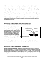
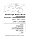
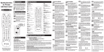
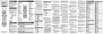
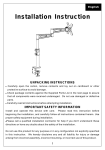
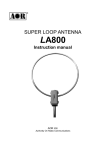
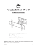
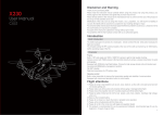
DC1 Anamorphic Lens with
ATH Transport shown
Panamorph Model DC1
Professional Grade
Home Cinema Lens System
USER MANUAL AND INSTALLATION GUIDE
Including MTH and ATH Transports
and AK8Pro-S and AK8Pro-L Projector Attachment Kits
As of February 1, 2011
Introduction
Basic projection parameters
A note on your screen format
Using AK8Pro Attachment Kit
Important ceiling mount location considerations
AK8Pro-S Attachment Plate Diagram
AK8Pro-L Attachment Plate Diagram
AK8ProS and AK8ProL Projector Compatibility Chart
Connecting the AK8Pro Attachment Plate
Alternate AK8Pro Attachment Plate Method
Mounting the MTH transport
Mounting the ATH transport
Final adjustments
Cleaning
Limited warranty
Contact information
Panamorph DC1 User Manual and Installation Guide, Version 1.1, copyright February, 2011. All rights reserved.
Page 1
2
2
2
3
3
4
5
6
6
7
8
9
9
10
10
10
INTRODUCTION
Thank you for purchasing the Panamorph DC1 lens system – the world’s first sealed, high
performance anamorphic lens system designed to dramatically enhance today’s 16:9 projectors when
showing the true widescreen 2.40 aspect ratio, the choice of most major motion picture directors.
The DC1 Lens System includes the DC1 Lens, ATH automated transport (or optionally the MTH
manual transport), plus the pre-engineered AK8Pro Attachment Kit and Chief mounting hardware
(RPA Kit). All parts necessary to quickly and easily mount your projector are included with the
Panamorph DC1 System. This manual provides detailed instructions for installing both the
Automated DC1 System and Manual DC1 System. The DC1 can also be installed as a fixed lens
system; however, that installation will not be covered in this manual.
DC1 BASIC PROJECTION PARAMETERS
Throw Distance (distance from projector lens to screen)
This distance should be between 12 and 21 feet (3.6M and 6.5M) with the standard DC1 lens. The
ideal range of 14.5 to 17.5 feet (4.4M to 5.3M) provides the highest pixel level clarity, especially for
applications at 1080 resolution. If your projection system involves a significantly longer throw
distance, we recommend contacting Panamorph Tech Support to determine if an optional correction
element is needed. Alternatively, visit www.panamorph.com for more information about our long
throw correctors.
Throw Ratio
Throw ratio primarily affects image distortion, sometimes referred to as “pincushion”, an inward
bowing that you will notice along the top and bottom of the projected image. To reduce this distortion:
-
Minimum throw should be at least 1.6 times the native 16:9 image width of the projector, or
2.85 times the screen height.
-
Throw may be reduced to 1.3 times the native image width (or 2.3 times the screen height)
with use of a curved screen. Use of a curved screen for very short throw distances can also
reduce non-uniform image brightness from your projector (hot spotting).
Image/Lens Shift
Horizontal lens/image shift other than fine adjustment is not recommended due to key-stone distortion
that can be introduced by the DC1. Vertical lens shift does not impact the use of the DC1. However,
note that with vertical lens shift the DC1 should be tilted to face the approximate center of the screen
to make any residual pincushion distortion symmetric at the top and bottom of the image.
A NOTE ON YOUR SCREEN FORMAT
The DC1 system works very well with a 2.35:1 aspect ratio screen. However, if you are considering a
new screen we highly recommend an aspect ratio of 2.40:1 for the best all around fit. The 2.35:1
aspect ratio is somewhat of a film industry designation for many aspect ratios around 2.35:1 and may
include many titles up to 2.40:1 and occasionally higher. Consequently, by following these installation
instructions we will help you optimize your constant height imaging performance for the three primary
aspect ratios of 16:9, 1.85:1 and the general range of 2.35:1-2.40:1.
Panamorph DC1 User Manual and Installation Guide, Version 1.1, copyright February, 2011. All rights reserved.
Page 2
USING AK8PRO ATTACHMENT SYTEM
The AK8PRO includes a high performance, rigid, solid steel plate specifically designed to attach to a
properly installed model RPA000 ceiling mount head made by Chief Manufacturing. This may then be
further installed to the ceiling using a variety of Chief components or the RPA Kit offered through
Panamorph. RPA Kits used with Panamorph Systems include the following Chief Manufacturing
components: 1-RPA000 Mount, 1-CMS115 ceiling plate, and 1-CMS003 3” extension pole.
The AK8PRO system mounts all the components on a common platform that does not generally
require additional support. There are, however, certain larger projectors where the use of supporting
chains will be required (these will be noted in the Projector Compatibility List on page 5 and
“ALTERNATE AK8PRO ATTACHMENT METHOD” on Page 6). The RPA and associated
hardware must be installed to structural ceiling members to support at least 250 pounds and
must be extremely rigid. Any play in the RPA mount will result in a rocking of the AK8PRO
assembly as the lens moves in and out of the projector beam and represents a danger to
equipment and personnel.
IMPORTANT CEILING MOUNT LOCATION CONSIDERATIONS
(If your Projector Requires the Alternate Attachment Method with Support Chains Please
Disregard this Step)
For optimum imaging results consult your projector’s instructions for the ceiling mount location to
place the projector’s lens in the horizontal center (i.e. left to right) of your projection screen (even if
your projector has a horizontal lens/image shift capability). In addition, make sure you are not at the
limits of your projector’s zoom capability so that you have some range for image adjustments.
The AK8PRO attachment plate is designed so that the variety of listed projectors and other attached
components form an average center of mass (gravity) approximately located at the center of the
ceiling mount pipe. Therefore, the ideal ceiling mount location will be shifted by the AK8PRO 2”
(50mm) toward the left side of the screen from the ceiling mount location indicated by your
projector’s instructions. If the plate is to be inverted (as directed in the plate diagram list) this shift will
be to the right side of the screen.
If your projector ceiling mount is already installed and you do not wish to move it (or similarly move
the screen in the opposite direction) due to a shift by the AK8PRO system, then you can make fine
horizontal shift adjustments to your projector (if available) combined with turning the projector (only as
necessary) during final setup to compensate for the shift. Some small amount of image distortion
(horizontal key-stoning) may result but in most cases this will not be noticeable since the image
edges will typically be masked by the screen borders.
WARNING!
Use extreme caution and appropriate hardware when installing heavy objects to a
ceiling. Periodically check all fasteners and connection hardware to be sure they are
not coming loose. Improper installation may lead to an increased risk of your
equipment becoming unstable and possibly injuring someone.
Panamorph DC1 User Manual and Installation Guide, Version 1.1, copyright February, 2011. All rights reserved.
Page 3
Front of AK8Pro-S Plate
2
2
M
C
Please note: Some
models may
M projector
M
require that the plate be
flipped over to obtain
correct plate orientation.
Please see attachment
list on page 6 for details.
M
10
4
H
7
13
11
M
M
3
11
6
6
15
13
1
16
H
17
16
18
Ceiling side of
Attachment Plate
H
1
5
8
7
8
20
19
9
19
M
10
14
12
10
5
9
4
4
17
12
14
15
4
13
3
2
11
7
3
H
1
11
1
2
8
10
8
19
20
8
M
M
4
19
18
14
2
8
15
13
9
7
3
12
16
3
2
3
Copyright.
June, 2008
1
15
16
17
1
6
6
5
1
6
6
8
11
5
7
11
8
4
7
4
2 10
2
10
3
6
AK8PRO-S ATTACHMENT PLATE DIAGRAM
Panamorph DC1 User Manual and Installation Guide, Version 1.1, copyright February, 2011. All rights reserved.
Page 4
6
Front of AK8Pro-L Plate
H
7
2
4
M
M
2
C
11
M
M
13
3
Please note: Some
projector models may
require that the plate be
flipped over to obtain
correct plate orientation.
Please see attachment
list on page 6 for details.
11
6
15
M
16
18
16
H
8
Ceiling side of
M Plate
Attachment
17
1
5
H
7
8
20
19
9
19
M
10
14
12
9
4
4
17
12
15
11
7
3
13
Top View of Plate
3
2
10
8
H
1
11
2
2
2
8
13
9
20
19
14
19
M
12
12
19
16
21
19
21
6
14 8
18 Copyright.
June, 2008
1
17
1
6
M
12
18 18
15
16
1
15
14
8
20
12
8
19
19
21
1
8
1
20
14
2
AK8PRO-L ATTACHMENT
PLATE DIAGRAM
20
2
18
Panamorph DC1 User Manual and Installation Guide, Version 1.1, copyright February, 2011. All rights reserved.
Page 5
AK8Pro-S Compatible Projectors
Projector Brand / Model
Holes
Screws
Spacers
Notes
Digital Projection Avielo Spectra
1
M4x25
3/8 (3)
Epson 7500, 9500, 9700
2
M4x30
5/8” (4)
Epson 31000, 61000
3
M4x30
5/8” (4)
InFocus IN81, IN82, IN83
4
M6x30
5/8” (3), 1/8”
(3), 3/8” (2)
Optoma HD80, HD81
5
M4x30
5/8” (3)
Optoma HD86
7
M4x30
3/8 (4)
Optoma HT7, HD82, HD8200
6
M6x25
5/8” (4)
Panasonic AE4000
8
M4x25
5/8” (4)
Sim2 C3X (and similar models)
10
M6x30
1/8” (3),
3/8” (3)
Sim2 Domino (and similar models)
11
M6x30
5/8” (4)
Projector Brand / Model
Holes
Screws
Spacers
Notes
Anthem LTX300, LTX500
2
M5x40
5/8” (4)
Flip plate over for correct attachment point orientation.
JVC RS15, RS35, HD 550, HD950
2
M5x40
5/8” (4)
Flip plate over for correct attachment point orientation.
JVC RS1, RS2, HD1, HD100
1
M5x40
5/8” (4)
Remove feet to expose mounting holes.
Marantz 11S2, 15S1
18
M5x30
5/8” (4), 1/8” (4)
Flip plate over for correct attachment point orientation.
Planar 8130, 8150/Runco LS
19
M4x30
5/8” (4)
Planar 7170
20
M4x30
5/8” (4), 1/8” (4)
*Support Chains Required,
Maximum screw depth of 10 MM
Projection Design Model 3, Optix
8
M6x30
5/8” (4)
(Standard zoom lens only)
Projection Design Helios
8
M6x30
5/8” (4)
*Support Chains Required
Sony VPL-VW50, VW60, VW85
12
M5x30
5/8” (3)
Sony VPL-VW70, 90
21
M5x30
5/8” (3)
Sony VPL-VW100, VPL-VW200
14
M5x30
5/8” (3)
Use 5/8” + 1/8” for three holes and 3/8” + 3/8” for remaining
– all holes using ¾” total.
Front hole–proj., 1/8” spacer, plate, 3/8” spacer, mount
Back holes–proj., 3/8” spacer, plate, 1/8” spacer, mount
AK8Pro-L Compatible Projectors
*Support Chains Required
CONNECTING THE AK8PRO ATTACHMENT PLATE
(Chief RPA000 mount and Phillips screwdrivers required)
1. Position the projector bottom-up, feet removed. Consult the Attachment Plate Diagram for plate
orientation, hole positions, and required screws and spacers for your projector model. Insert and
tighten each screw through an appropriate silver washer and lock washer, the designated holes in the
Attachment Plate, then through any required spacers and finally into the projector ceiling mount
holes.
Panamorph DC1 User Manual and Installation Guide, Version 1.1, copyright February, 2011. All rights reserved.
Page 6
2. Using the included gold hex key, install the six 7/8” socket head screws each through a 3/8”
aluminum spacer and into the six threaded holes from the ceiling side of the attachment plate.
Thread only enough to extend the screw to the bottom of the plate.
3. Insure that the RPA000 mount head is secure (see instructions included with the RPA000 mount)
and oriented properly relative to the 7/8” socket head screw heads so that the mounted projector will
face the screen. Use two people to lift and position the projection assembly so that the heads of each
of the 7/8” socket head screws rest within the matching final location of the RPA000 mount head. At
this point the silver 3/8” spacers should be between the Attachment Plate and the RPA000 mount
head. The projection assembly may be lowered to allow the 7/8” screw heads to rest on the RPA000
mount. However, a first person should continue to guide the projection assembly while and a second
person uses the gold assembly wrench to tighten the 7/8” screws. When tightening these screws, do
so in a pattern of incrementally driving each screw a little more into the attachment plate so that at
any time the projection assembly is resting on as many screw heads as possible until all are
tightened.
If the lens must be removed for any length of time it is recommended that a similar weight be
suspended from the front of the attachment kit to balance the weight of the projector. This will
minimize unusual stresses on the ceiling mount system.
ALTERNATE AK8PRO ATTACHMENT PLATE METHOD
For Larger Projectors Requiring Support Chains (See compatibility list on Page 5 and Page 7)
(Phillips screwdrivers, pliers, scissors and appropriate ceiling hooks required)
Plate Hook Bag Contents (AK6 only)
#8-32 Wire Hook (2)
#8-32 Nut (4)
#8 Washer (4)
Ceiling
side
M4 Lock Washer (2)
3/16” Chain (6 feet)
Chain End (4)
Plate Hook
as assembled to
Attachment Plate
Ceiling Mount
Attachment
1. Install the Plate Hook Assemblies in the two “H”
adapter
Screws
holes of the Attachment Plate (see diagram) with the
Attachment
Plate
hook ends on the ceiling side as shown above. Use
Spacers
pliers to bend the closed hooks apart just enough to
install a Chain End (See Step 5).
2. Position the projector bottom-up. Consult the
Attachment Plate Diagram for plate orientation, hole
positions, and required screws and spacers for your
projector model. Insert and tighten the required
screws through the ceiling mount adapter (not included), then through the designated holes of the
Attachment Plate, and then through any required spacers and finally into the projector ceiling mount
holes. If the screws in the kit are not long enough, procure the longest metric screws you can
for the safest installation.
Panamorph DC1 User Manual and Installation Guide, Version 1.1, copyright February, 2011. All rights reserved.
Page 7
3. Securely connect the projector assembly to the ceiling mount and then adjust the projector and
ceiling mount to center the projector's image in the horizontal center of your screen.
4. Install ceiling hooks (not supplied) into the ceiling directly above the Plate Hooks. The ceiling
hooks should be small enough to accept a Chain End but strong enough when installed to
each support 40 pounds or more.
5. Attach a Chain End to the Chain and then connect to one of the ceiling hooks. Cut the Chain and
assemble to another Chain End for a best fit to the corresponding Plate Hook and attach. Repeat for
the other set of hooks.
6. Adjust and tighten the nuts on the Plate Hook Assemblies to make the Chains tight but without
raising the front of the Attachment Plate. You may wish to turn the projector on to ensure the image
remains properly oriented to the screen during this step. At this point, proceed to the appropriate
lens/transport mounting step.
MOUNTING THE ATH AUTOMATED TRANSPORT
1.
DO NOT CONNECT POWER TO THE TRANSPORT AT THIS TIME.
2.
Position the flat side of the motorized
transport against the bottom of the
Attachment Plate so that the transport logo is
toward the screen and the center “C” hole in
the Attachment Plate is aligned with the front
recessed transport hole. Insert the #10-32
pivot screw up through the transport and
Attachment Plate and loosely complete the
assembly with the corresponding washer, lock
washer and nut. Now loosely insert the four
#6-32 3/8” screws through the four “M” slots
in the top of the Attachment Plate and down
into the transport.
ATH Attachment Bag Contents
#10-32x5/8” screw (1)
Pivot screw as
assembled
#10-32 nut (1)
Attachment
Plate
#10-32 lock washer (1)
#10-32 washer (1)
#6-32x3/8” screw (4)
ATH mount
3.
Remove the DC1 Lens Bracket from the box and refer to page 7 of the Owner’s Manual
included in the ATH kit for details on installation. The Lens Bracket should be oriented so that its fork
arms face the screen.
MOUNTING THE MTH MANUAL TRANSPORT
Installing without attachment kits. The MTH may be mounted to ceiling structures without using
the AK8Pro attachment kit. Two black #10x1¼” long mounting screws are included with the MTH for
mounting through the centers of the two ceiling mount slots in the MTH body. These centers should
correspond to two mounting points in a secure platform in front of your projector so that the DC1 can
be properly positioned in front of and as close to the projector lens as possible without mechanically
interfering with the projector or its ventilation in either “lens in” or “lens out” positions.
Panamorph DC1 User Manual and Installation Guide, Version 1.1, copyright February, 2011. All rights reserved.
Page 8
The optical design of the DC1 is very forgiving, so minor deviations in this positioning or any
moderate warming around a projector vent will have no impact on image quality. In addition, note
that in a ceiling mounted system, the center of your projector beam will exit the projector lens below
center. The DC1 will ultimately be aligned with the beam itself and not the projector lens. As a
result, you should expect the DC1 to be centered below the projector lens and, ultimately, tilted
downward. Before final tightening of the mounting screws, refer to the “Final Adjustments” step
below.
1.
Remove the DC1 Lens Bracket From the shipping box. Securely attach the Lens Bracket to
the MTH1 shuttles using the eight M3x6mm brass screws and black washers included in the MTH1
kit. The Lens Bracket should be oriented so that its central threaded hole is aligned with the long slot
in the body of the MTH1 and that the forked arms are facing the screen.
2.
If using an AK attachment kit, position the MTH1 to the bottom of the installed AK Attachment
Plate so that the detailed side (front) of the MTH1 body is facing the projection screen. Insert each of
the four M3x16mm Phillips screws through a lock washer and flat washer from the MTH1 kit, through
the four “M” slots in the Attachment Plate and into the corresponding holes in the MTH1 body.
Tighten only to the point that the MTH1 is against the Attachment Plate but is still relatively free to be
oriented or “pivoted” in the “M” slots.
3.
Now carefully install the DC1 Lens into the Lens Bracket using the two ¼” #6-20 screws and
black washers with the included gold hex key. Proceed to “Final Adjustments” step below.
FINAL ADJUSTMENTS (ALL INSTALLATIONS)
1.
Turn the projector on with the DC1 Lens out of the projector beam. Set the horizontal lens
shift to neutral (if a feature of your projector) and then adjust the ceiling mount so that the 16:9 image
is in the exact center of and square to the screen, with a similar amount of image slightly over the top
and bottom screen borders. If the projector lens is not in the exact horizontal center of the screen you
may need to use a little horizontal lens shift for this purpose.
2.
Bring the DC1 Lens into the beam. Adjust the vertical position and tilt of the Lens so that the
projector beam is passing through the center of the Lens and so any residual pincushion distortion is
about the same at the top and bottom of the image. This will typically result in the DC1 Lens being
below the center of the projector lens and tilted slightly downward. Tighten the screws then lock the
lens in place by tightening the small silver set screw with the provided hex wrench.
3.
Adjust the rotation of either the ATH or MTH transport so that the left and right sides of the
image are an equal distance from their respective screen borders. Now tighten the Pivot Screw
(ATH) and also the four remaining screws holding the transport to the Attachment Plate.
4.
For optimum multiple aspect ratio performance, adjust the projector’s zoom so that a 1.85:1
aspect ratio movie (Panamorph “out”) is just masked by the top and bottom of the screen border.
This way 1.85:1, 16:9 and 2.35-2.4:1 aspect ratio movies should all be presented to fill the screen at a
constant height.
Panamorph DC1 User Manual and Installation Guide, Version 1.1, copyright February, 2011. All rights reserved.
Page 9
CLEANING
In most applications lenses do not need very much cleaning – a bit of dust will not impact image
clarity. However, in today’s high performance home cinemas with very dark rooms a small build-up of
dust or other foreign matter on your projector lens or your Panamorph lens can produce a
measurable reduction in contrast. The most effective cleaning approach is to simply blow off any
dust. If there is any residue or build-up then it is recommended that you clean the optics with
professional lens cleaning supplies such as from a camera store while the lens is in front of the lit
beam of the projector. This will allow you to quickly see both the results of cleaning and also if you
are causing any damage.
LIMITED WARRANTY
Panamorph, Inc. warrants this product to be free of defects in original workmanship and material for a period of eighteen
months from the date of manufacture listed on or inside its shipping container. During this period, a defective unit may be
repaired or replaced, at the discretion of Panamorph, Inc., by returning it in its original packaging with a copy of your receipt.
This warranty does not cover damage resultant from lack of prudent care, accident or misuse (including the use of motor
systems with lenses or other products in ways not intended), or any cosmetic damage not reported within 15 days of
purchase. Damages are limited to the cost of the product. A service charge may be applied to any returned product requiring
cosmetic attention, or to the repair of any damage not covered under this warranty.
This warranty is non-transferrable and applies only to products and/or components purchased by original end users
through authorized Panamorph channels operating in compliance with Panamorph policies, terms and conditions.
Panamorph, Inc.
1755 Telstar Drive, Suite 103
Colorado Springs, CO 80920
719-266-2680
www.panamorph.com
Panamorph DC1 User Manual and Installation Guide, Version 1.1, copyright February, 2011. All rights reserved.
Page 10