1
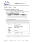
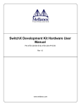
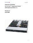
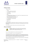
MTS3600 Installation Guide
Internally Managed vs Unmanaged (Externally Managed)
The following table shows which switches come with a management CPU and which do not. Managed switches can be upgraded from simple chassis management to full fabric management by
purchasing an additional license. For more information on buying a license see the user’s manual.
Unmanaged switches are plug and play out of the box. All switches come with the latest FW
burned on the Flash and EEPROM. Update the FW on unmanaged swithces in-band only. When
new FW is available you will receive an email with the link to the Mellanox FW download site.
The download site has the Mellanox FW tool package and full instructions for updating FW.
All managed switches have internal chassis management. With the purchase of a license this management module can manage the IB fabric. See Table 1 for details.
Table 1 - Switch Management
Family
MTS3600-UNC
Managed /
Unmanaged
Unmanaged
Management Connections
Plug and play
All firmware updates should be done in-band using Mellanox Firmware Management Tools. I2C port access using MTUSB-1 device is required for firmware updates if in-band burning is not possible.
No Management
MTS3600-BNC
Managed
RS232 cable DB9 to DB9 included in the box to connect to host PC for initial
configuration of the switch. After initial configuration the switch can be managed through the ethernet using a remote connection.
Chassis Management is included with purchase, and an additional fabric management option, FabricIT-EFM, can be used with purchase of an additional
license.
Should your unmanaged switch have CONSOLE, Ethernet, and USB connectors, they will not
work. Only the I2C connector will work on unmanaged switches.
Installing the Switch in the Rack
Minimum and Maximum Rack Depth for these switches
This switch can be installed in any standard 19”racks with depths of 670mm to 900mm.
Mellanox Part Numbering Legend
Table 2 - Part Numbering Legend
Place
Field
MT
Mellanox Technologies
S
System Type
Mellanox Technologies Inc.
Document Number
3049
Decoder
S = Switch
350 Oakmead Parkway, Sunnyvale, CA 94085
Tel: 408-970-3400
Fax: 408-970-3403
www.mellanox.com
Rev 1.6
Rev 1.6
Table 2 - Part Numbering Legend
Place
Field
Decoder
MM
Model
36 = InfiniScale IV
FF
Form factor
00 = Rack mounted switch, 10 = Chassis
C
InfiniBand Port Config.
G = CX4 DDR, J = CX4 QDR, Q = QSFP QDR, R = QSFP DDR,
-
Separator
P
# Power Supplies
0 = 0, 1 = 1, 2 = 2
M
Management
U = Unmanaged, B = Managed
Y
Module Config.
N = IB modules
R
RoHS
C = RoHS w/ Exemption, R = RoHS Lead-Free
Tools and Parts
Tools required and customer supplied parts
• Phillips Screwdrivers #1 and #2
• ESD Strap
• ESD mat
• Grounding screw
• Grounding wire sufficient to reach a valid ground
Parts included in the installation kit:
• 2 rails
• 2 rail slides
• 8 pan head screws M6
• 8 recessed flat head screws
• 4 caged nuts
• 2 metal washers
Figure 1: Rack Installation Kit Parts
rail
rail slide
2
Mellanox Technologies
Rev 1.6
Before you install your new switch, unpack the system and check to make sure that all the parts have been
sent, check this against the parts list. Check the parts for visible damages that may have occurred during
shipping.
Note: If anything is damaged or missing, contact your customer representative immediately.
Procedure
Step 1.
Step 2.
Place the ESD mat on the floor where you will be working and put on the ESD strap. Make
sure the ESD strap is touching your skin and that the other end is connected to a verified
ground.
Choose which side of the switch you want even with the vertical rack support. Either
the side with the power supply units or the side with the IB connectors can be even
with the vertical rack support. The other side of the switch will be further inside of the
rack.
Things to consider before choosing where to mount the rails and rail slides.
Figure 2: Which Side of the Rack Do You Want the Connectors?
The distance between the rack and the door can be as little as 4 cm on one side
of the rack and as much as 18 cm on the other side of the rack. Keep in mind that
there can be as many as 36 cables connected to the switch.
•
•
Do you want the connector side recessed in the rack to allow for larger cable bending radius?
Will the connector side be recessed past other equipment in the rack and will this be problematic?
Note: The rails are to be installed on the side of the rack where the switch will be recessed into
the rack.
Step 3.
Install the rail slides onto the switch. Place the end of the rail slide with the 90o angle
on the side of the switch that you want to be even with the vertical support of the 19”
rack. Use four of the flat head screws for each rail slide. There are two sets of holes in
the rail slide. Select the set of holes to either mount the switch closer or farther away
from the rack vertical support. Tighten the screws to 3Nm or 26.5 pound inches.
Mellanox Technologies
3
Rev 1.6
This side of the
switch will be next
to the vertical rack
support.
Step 4.
Step 5.
Step 6.
Step 7.
Step 8.
Step 9.
Step 10.
4
Clip the nuts into the holes in the rack you will be using to connect the rail slides.
Check that both sides of the switch are in the same position number on the rack.
Using two of the pan head screws and one washer, for each rail, install the rails to the
other end of the rack. Place the rail behind the holes in the rack and screw the screws
through the holes in the washer then through the rails. Tighten the pan head screws
that hold the rails to 9.2 Nm or 81.5 pound inches.
Place the four bolts for the caged nuts within reach.
Slide the switch into the rails.
Put the switch into place and screw the bolts into the nuts from step 4. Tighten the
bolts to 9.2 Nm or 81.5 pound inches.
Tighten all of the screws.
Plug in the power cables.
Mellanox Technologies
Rev 1.6
Step 11.
Check the Status LEDs and confirm that all of the LEDs show status lights consistent
with normal operation.
During the boot phase the status LED may show RED. It can take up to
3 minutes to boot up. Should the Status LED not change to GREEN after
3 minutes troubleshoot the switch!
Warning: Any YELLOW status LEDs is cause for concern and must be
dealt with immediately.
Step 12.
You can start connecting all of the cables to the switch.
Grounding the Switch
You must install an external ground to all IT components. Connect a ground wire to one of the casing
screws connect the other end to a valid ground. Do not rely on the power connection ground. If you choose
to not use the ground screw, make sure that there is a valid ground connection between the chassis of the
switch and the grounded rack. Test the ground using an Ohm meter.
Note: Grounding wires, screws, and connectors for the ground are not supplied by Mellanox.
Configuring the Switch for the First Time
Unmanaged (Externally managed) Switches
Note: Unmanaged (Externally managed) switches, that is the the MTS 3600-UNC do not get configured.On unmanaged switches, the CONSOLE, Ethernet, and USB connectors do not work.
Note: The unmanaged switches are Plug and Play and all firmware updates should be done in-band. The
I2C connection should only be used if the FW image was corrupted to the point that the regular FW
tools cannot successfully reburn the correct image.
When you install the switch, it comes with the latest firmware burned on the board. You will not need to burn FW
unless you get notification from Mellanox that a newer version of FW for your switch has been released.
Managed (Internally managed) Switches
Step 1.
Connect the host PC RS232 connector to the CONSOLE port of the MTS3600 switch using
the supplied cable.
Connect the host
PC to here
I2C
CONSOLE
OK
!
System
Fans
PSU 1
PSU 2
OK
~AC
Note: No remote IP connection is available at this stage.
Mellanox Technologies
5
Rev 1.6
Step 2.
Configure a serial terminal program (for example, HyperTerminal, Minicom, or Tera
Term) on your host PC with the settings described in Table 3.
Table 3 - Serial Terminal Program Configuration
Step 3.
Step 1.
Parameter
Setting
Baud Rate
Data bits
Stop bits
Parity
Flow Control
9600
8
1
None
None
Login (from serial terminal program) as admin and use admin as password. This starts
the Mellanox configuration wizard.
Go through the Mellanox configuration wizard. Table 4 shows an example of a wizard session.
Table 4 - Configuration Wizard Session - IP Configuration by DHCP (Sheet 1 of 2)
Wizard Session Display (Example)
Comments
Mellanox configuration wizard
Do you want to use the wizard for initial configuration? yes
You must perform this configuration the first time you operate the
gateway or after resetting the
gateway password. Type ‘y’ and
then press <Enter>.
Step 1: Hostname? [bridge-1]
If you wish to accept the default
hostname, then press <Enter>.
Otherwise, type a different hostname and press <Enter>.
Step 2: Use DHCP on eth0 interface? Yes
Perform this step to obtain an IP
address for the gateway. (eth0 is
the management port of the gateway.)
If you wish the DHCP server to
assign the IP address, type ‘yes’
and press <Enter>.
If you type ‘no’ (no DHCP), then
you will be asked whether you
wish to use the ‘zeroconf’ configuration or not. If you enter ’yes’
(yes Zeroconf), the session will
continue as shown in Table 5.
If you enter ’no’ (no Zeroconf),
then you need to enter a static IP,
and the session will continue as
shown in Table 6.
6
Mellanox Technologies
Rev 1.6
Table 4 - Configuration Wizard Session - IP Configuration by DHCP (Sheet 2 of 2)
Wizard Session Display (Example)
Step 3: Admin password (Enter to leave unchanged)?
<new_password>
Step 4: Confirm admin password? <new_password>
Comments
To avoid illegal access to the
machine, please type a password
and then press <Enter>. Then
confirm the password by reentering it.
Note that password characters are
not printed.
You have entered the following information:
1. Hostname: <bridge-1>
2. Use DHCP on eth0 interface? : yes
3. Admin password (Enter to leave
unchanged): (CHANGED)
The wizard displays a summary
of your choices and then asks you
to confirm the choices or to reedit them.
To change an answer, enter the step number to return to.
Otherwise hit <enter> to save changes and exit.
Either press <Enter> to save
changes and exit, or enter the
configuration step number (1, 2
or 3) that you wish to return to.
Choice: <Enter>
Configuration changes saved.
To return to the wizard from the CLI, enter the “configuration
jump-start” command from configuration mode. Launching CLI...
bridge-1 >
Note:
To run the command "configuration jump-start, you must be in
Config mode.
Mellanox Technologies
7
Rev 1.6
Table 5 - Configuration Wizard Session - IP Zeroconf Configuration
Wizard Session Display - IP Zeroconf Configuration (Example)
Mellanox configuration wizard
Do you want to use the wizard for initial configuration? y
Step 1: Hostname? [bridge-112428]
Step 2: Use DHCP on eth0 interface? [no]
Step 3: Use zeroconf on eth0 interface? [no] yes
Step 4: Default gateway? [192.168.10.1]
Step 5: Primary DNS server?
Step 6: Domain name?
Step 7: Admin password (Enter to leave unchanged)?
You have entered the following information:
1. Hostname: bridge-112428
2. Use DHCP on eth0 interface: no
3. Use zeroconf on eth0 interface: yes
4. Default gateway: 192.168.10.1
5. Primary DNS server:
6. Domain name:
7. Admin password (Enter to leave unchanged): (unchanged)
To change an answer, enter the step number to return to.
Otherwise hit <enter> to save changes and exit.
Choice:
Configuration changes saved.
To return to the wizard from the CLI, enter the "configuration jump-start"
command from configure mode. Launching CLI...
bridge-1 >
8
Mellanox Technologies
Rev 1.6
Table 6 - Configuration Wizard Session - Static IP Configuration
Wizard Session Display - Static IP Configuration (Example)
Mellanox configuration wizard
Do you want to use the wizard for initial configuration? y
Step 1: Hostname? [bridge-112428]
Step 2: Use DHCP on eth0 interface? [yes] n
Step 3: Use zeroconf on eth0 interface? [no]
Step 4: Primary IP address? 192.168.10.4
Mask length may not be zero if address is not zero (interface eth0)
Step 5: Netmask? [0.0.0.0] 255.255.255.0
Step 6: Default gateway? 192.168.10.1
Step 7: Primary DNS server?
Step 8: Domain name?
Step 9: Admin password (Enter to leave unchanged)?
You have entered the following information:
1. Hostname: bridge-112428
2. Use DHCP on eth0 interface: no
3. Use zeroconf on eth0 interface: no
4. Primary IP address: 192.168.10.4
5. Netmask: 255.255.255.0
6. Default gateway: 192.168.10.1
7. Primary DNS server:
8. Domain name:
9. Admin password (Enter to leave unchanged): (unchanged)
To change an answer, enter the step number to return to.
Otherwise hit <enter> to save changes and exit.
Choice:
Configuration changes saved.
To return to the wizard from the CLI, enter the "configuration jump-start"
command from configure mode. Launching CLI...
bridge-1 >
Step 2.
Before attempting a remote (for example, SSH) connection to the gateway, check the
eth0 interface configuration. Specifically, verify the existence of an IP address. To
check the current eth0 configuration, enter the following commands:
bridge-112428> enable
CLI
bridge-112428# show interface eth0
mode
// Enter ‘enable’ mode of
// # indicates ‘enable’
Mellanox Technologies
9
Rev 1.6
The following is an example of the output:
Interface eth0 state
Admin up:
yes
Link up:
yes
IP address:
192.168.10.6
Netmask:
255.255.255.0
Speed:
100Mb/s (auto)
Duplex:
full (auto)
Interface type:
ethernet
Interface source:
physical
MTU:
1500
HW address:
00:00:50:3A:8E:80
Comment:
RX
RX
RX
RX
RX
RX
RX
bytes:
packets:
mcast packets:
discards:
errors:
overruns:
frame:
123102
1271
0
0
0
0
0
TX
TX
TX
TX
TX
TX
TX
bytes:
packets:
discards:
errors:
overruns:
carrier:
collisions:
122850
1119
0
0
0
0
0
bridge-112428#
Step 4.
Before attempting a remote (for example, SSH) connection to the switch, check the
eth0 interface configuration. Specifically, verify the existence of an IP address. To
check the current eth0 configuration, enter the following commands:
switch-1 > enable
switch-1
# show interface eth0
// Enter ‘enable’ mode of CLI
// # indicates ‘enable’ mode
The following is an example of the output:
Interface eth0 state
10
Mellanox Technologies
Rev 1.6
Admin up:
Link up:
IP address:
Netmask:
Speed:
Duplex:
Interface type:
Interface source:
MTU:
HW address:
Comment:
RX bytes:
RX packets:
RX mcast packets:
RX discards:
RX errors:
RX overruns:
RX frame:
TX bytes:
TX packets:
TX discards:
TX errors:
TX overruns:
TX carrier:
TX collisions:
switch-1 #
yes
yes
192.168.10.6
255.255.255.0
100Mb/s (auto)
full (auto)
ethernet
physical
1500
00:00:50:3A:8E:80
123102
1271
0
0
0
0
0
122850
1119
0
0
0
0
0
FabricIT
FabricIT EFM is a software based management system that can be run with either a command line interface or with a WebUI interface. Chassis management comes with the switch system. An optional license is
required for full use of FabricIT cluster management. See the FabricIT EFM User Manual for instructions
and commands available to manage the chassis, switches, and fabric.
Installing Licenses
A license for extended FabricIT management and inspection features with FabricIT EFM software is available for an additional licensing fee.
Downloading FabricIT Software and Documents
To download FabricIT software and documentation, please visit the following Web page:
FabricIT http://www.mellanox.com/content/pages.php?pg=fabric_it_login.
Note that you will need to enter the License Entitlement number and the Switch S/N to obtain the
software and documentation, and also to generate an EFM license that enables extended FabricIT
management and inspection features on your switch system.
Mellanox Technologies
11
Rev 1.6
FabricIT Management and Inspection License
If your switch system includes an internal management, then to activate extended FabricIT management and inspection features you need to install the license that was purchased along with the
switch system. Without the license, you will not be able to run a Subnet Manager on the switch nor
run advanced fabric diagnostics.
For information on installation, please refer to the FabricIT Enterprise Fabric Management Software CLI User’s Manual.
Starting an SSH Connection to the Switch
Note: SSH connection also supports TelNet.
Step 1.
Step 2.
Step 3.
Set up an Ethernet connection between the switch and a local network machine (“the remote
machine” henceforth) using a standard RJ-45 connector.
Connect to the remote machine.
Start a remote shell to the switch using the following command:
ssh –l admin <your ip address>
When prompted for a password enter “admin”.
Note that the IP address used above is the same IP address that was assigned to the Mellanox configuration wizard in the “Configuring the Switch for the First Time” section.
Step 4.
You can enter any supported command now.
Note: For a complete reference of commands, please see Mellanox FabricIT Management Software User’s
Manual.
Starting a WebUI Connection to the Switch
Step 1.
Step 2.
Set up an Ethernet connection between the switch and a local network machine (“the remote
machine” henceforth) using a standard RJ-45 connector.
Start a Web browse – Internet Explorer 7.0 or Mozilla Firefox 3.0.
Note: Make sure the screen resolution is set to 1024*768 or higher.
Step 3.
12
Enter as URL the following: http://<switch_IP_address>
where <switch_IP_address> is the IP address of the switch or its DNS name.
Mellanox Technologies
Rev 1.6
Step 4.
You will receive the login window for remote management of the switch.
Step 5.
Use admin for both the login (Account) and the password.
The MTS3600 Series User Manual can be found at:
http://www.mellanox.com
=>Products=>Switches=>InfiniBand Switch Systems=>MTS3600
Mellanox Technologies
13