1
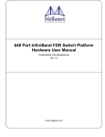
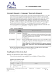
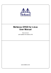
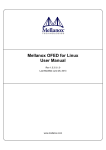
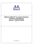
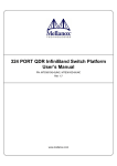
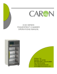
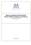
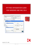
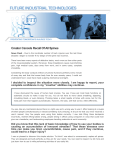
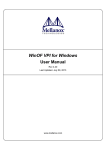
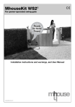
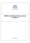
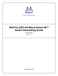
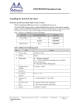
MTS3610 Installation Guide
Package Contents
The package includes:
•
1 Chassis
•
1-18 leafs according to the amount ordered
•
18 - X leaf blanks X = the amount ordered
•
1 leaf fan module
•
1 spine fan module
•
9 spines
•
1- 2 management modules according to the amount ordered. If only 1 management module is ordered
then one MM blank will be in the package.
•
6-8 power cables depending upon your specific order
•
6-8 PSUs depending upon your specific order
•
(8 - X) PSU blanks X = the amount ordered
•
RJ45 to DB9 cable
•
1 Installation kit
•
CD
•
Installation guide
Before you install your new MTS3610 Chassis, unpack the system and check to make sure that all the parts
have been sent, check this against the parts list. Check the parts for visible damages that may have occurred
during shipping.
Note: If anything is damaged or missing, contact your customer representative immediately.
Physical Installation
Warning: This equipment is very heavy. Safety is the first concern. The fully
loaded chassis weighs ~350 lbs (155 kg). Make sure that proper manpower and
equipment are used for transporting and moving the chassis.
Note: You will need a mechanical lift, to move and insert the chassis into the rack.
This chassis can be installed in 19” racks with a maximum depth of 81cm.
The switch platform uses 20U of rack space in a standard 19” rack. The switch ships from the factory with
mounting racks on the front side. There are four threaded connectors on the top of the chassis for connecting
eye bolts. The four eye bolts are included in the installation kit. The chassis can be lifted using these four eye
bolts and a mechanical lift. The switch is supported from underneath the unit by a shelf.
Choose a rack which is able to support the mechanical and environmental characteristics of a fully populated
switch chassis as listed in the user manual.
Mellanox Technologies Inc.
Document Number
3082
350 Oakmead Parkway, Sunnyvale, CA 94085
Tel: 408-970-3400
Fax: 408-970-3403
www.mellanox.com
Rev 1.2.2
MTS3610 Installation Guide
Note: A 20U mounting space is required for proper installation of the switch platform.
The rack mounting holes conform to the IEA-310 standard for 19-inch racks.
Guarantee proper ventilation, by leaving 8cm (3”) of space to the front and rear
of the switch. This will ensure proper air flow through the chassis. This is crucial for maintaining good airflow at ambient temperature. In particular, route
cables such that they do not impede the air into or out of the chassis.
ESD Connection
Before starting any procedure on the MTS3610 Switch system:
Step 1.
Put an ESD prevention wrist strap on your wrist, and make sure there is good contact between
your body and the strap.
Step 2.
Plug the other end of the wrist strap to the MTS3610 chassis ESD connector on the
front of the switch system or connect it to a valid ground. Make sure that this is a tight
fit.
Figure 1: ESD Connector
ESD connector
Installing the Chassis
You will need:
•
#2 phillips screwdriver
•
a mechanical lift
•
a grounding lug
•
ground wire of sufficient length and gauge to properly ground the chassis
Parts included in the installation kit:
•
•
•
•
•
Rev 1.2.2
1 shelf
1 lock down bar
4 eye bolts
2 rail slides
1 right hand cable holder
•
•
•
•
•
5 Allen head screws
5 washers
1 Allen wrench
26 sets of caged nuts and bolts
1 left hand cable holder
Mellanox Technologies
2
MTS3610 Installation Guide
Figure 2: Installation Kit Parts
Lock down bar
Rail slide
Eye bolts
Caged nuts and bolts
Right and Left
Cable holders
Before starting the procedure, put the ESD strap on and connect it to a valid ground.
Installing the Bottom Shelf
Step 1.
Select the location in the rack. Try to keep the chassis as low as possible to keep the center of
gravity low.
Choose which way you want the chassis to face in the rack. Keep in mind that one side of the chassis can
have up to 324 cables connected. The other side of the chassis will have power cables. The distance between
the rack and the door will be small on one side of the rack as opposed to the other side of the rack.
Rev 1.2.2
Mellanox Technologies
3
MTS3610 Installation Guide
Figure 3: Vertical Rails to Cabinet Measurement
Note: The side of the chassis with the power supply units will sit flush with the vertical supports of the rack.
The side of the chassis with the QSFP connectors will sit at the edge of the shelf closer to the center of the
rack.
Note: place the chassis as low as possible in the rack to keep the center of gravity as low as possible.
Step 2.
Insert four caged nuts into the rack on the side you plan to have the connectors. Note
the U number on the rack.
Figure 4: Caged Nut Insertion
Step 3.
Screw the rail slides onto the rack.
Figure 5: Rail Slide Installation
The caged nuts
are separated by a
single space.
Step 4.
Insert four caged nuts into the rack on the side you plan to have the powers supplies,
and spines. Use the same U number on this side of the rack as you used on the rail
side of the rack.
Step 5.
Prepare the four bolts and keep them within reach.
Step 6.
Slide the shelf onto the rail slides.
Step 7.
Connect the shelf to the rack.
Rev 1.2.2
Mellanox Technologies
4
MTS3610 Installation Guide
Figure 6: Shelf Installation
Step 8.
Tighten all eight bolts into the caged nuts.
Inserting the Chassis
Step 1.
Screw the four Eye bolts to the four corners of the top of the chassis.
Step 2.
Connect the eye bolts to a Mechanical lifting device.
Figure 7: Mechanical Lifting Device
Step 3.
Raise the chassis 2 cm (1”) above the level of the shelf.
Step 4.
Move the chassis over the shelf. Place the chassis so that the face plate of the chassis
is a few inches from the vertical rack support.
Step 5.
Lower the chassis onto the shelf.
Step 6.
Remove the mechanical lifting device.
Step 7.
Place ten caged nuts into the vertical rack support at the locations corresponding to
the holes in the chassis faceplate.
Rev 1.2.2
Mellanox Technologies
5
MTS3610 Installation Guide
Figure 8: Face Plate Mounting Bolt Locations
Holes in the
faceplate for
mounting on the
rack.
Step 8.
Slide the chassis onto the shelf until the face plate of the chassis touches the vertical
rack support.
Step 9.
Screw the bolts through the faceplate into the caged nuts, and tighten all ten bolts and
nuts.
Step 10.
Place the lock down bar over the lip of the chassis, and align the holes in the lock
down bar with the holes in the shelf.
Figure 9: Lock Down Bar
The lock down bar goes
over the lip on the bottom of the chassis.
Step 11.
Place a washer on each Allen screw and screw down the lock down bar to the shelf
using the Allen wrench supplied. Use all 5 Allen screws.
Step 12.
Connect a valid ground to the grounding post.
Rev 1.2.2
Mellanox Technologies
6
MTS3610 Installation Guide
Ground Connections
Make sure to connect the ground post to a valid electrical ground. Use a grounding lug and a ground wire of
sufficient capacity to safely convey a potential discharge. The chassis is concurrently grounded through each
of the PSUs. Only connect the PSU cords to properly grounded outlets. Do not rely on the PSU grounds. It is
absolutely necessary to connect the grounding post. Make sure the connections are solid and permanent.
Figure 10: Ground Connection
Grounding
post
Grounding lug
Installing the Cable Holder
Left side
rack
Top side
Holes for
connecting
the cable
holder to the
rack
X8
X8
Right side rack
Bottom side
Step 1.
Place the Cable holder next to the rack and identify the holes for the caged nuts. The numbers
on the cable holders should face each other.
Step 2.
Put the caged nuts into the previously identified holes in the rack.
Rev 1.2.2
Mellanox Technologies
7
MTS3610 Installation Guide
Step 3.
Screw the cable holder onto the rack using the screws provided.
Step 4.
Repeat steps 1 to 3 for the second cable holder.
Powering Up the Switch Platform
Note: Make sure that the power cords are compatible with your outlets. Power cords for different countries
can be ordered from Mellanox.
Step 1.
Plug in the power cords to the PSUs.
AC
DC
OK
Step 2.
OK
FAIL
Clamp each power cord to the chassis.
Each PSU has a clamp next to it, for supporting the power cord. Use this clamp to remove possible strain on
the PSU. The length of power cord between the clamp and the PSU must be less than 6” (15cm). See
Figure 11,“Electrical Cable Clamp”.
Step 3.
Plug the other end of the power cord into a grounded outlet.
Note: It is recommended that the power to all of the power supplies be turned on at the same time.
Step 4.
Repeat steps 1 to 3 for each of the remaining power supply units.
Note: A fully loaded MTS3610 switch system can draw 5.2 kW of power. Make sure that the outlets and
circuits will not be overloaded. Spread out the load over at least two or three circuits.
Figure 11: Electrical Cable Clamp
Clamp to remove strain on
the plug
The switch system requires at least six PSUs to operate a fully populated platform. The seventh and eighth
PSUs provide a fail over protection mechanism such that the system will continue operating if one or more
of the PSUs fail. Connecting the PSUs to different AC lines provides AC fail over protection.
The system should continue to run and allow a hotswap of a defective PSU even if it has only six PSUs.
Step 5.
As soon as a switch is plugged in, make sure that the green power LEDs on the PSUs
are on.
Step 6.
Check the Status LEDs on all of the management modules and confirm that all of the
LEDs show status lights consistent with normal operation.
Warning: Any yellow status LEDs on any of the management modules is cause
for concern and must be dealt with immediately.
Rev 1.2.2
Mellanox Technologies
8
MTS3610 Installation Guide
Step 7.
Check that none of the ATTN status LEDs on the spines are yellow.
Step 8.
Go around to the other side of the switch chassis and check the leaf board status
LEDs.
This LED should be off.
The green connector
LEDs should be on.
This LED should be on.
Step 9.
The yellow connector
LEDs should be
blinking.
Check that the leaf physical and data link status LEDs in the spines are lit.
ATTN – Yellow indicates fault
in spine, normally off
Links A and B to each leaf
Green – indicates Power OK
Leaf numbers
Yellow – indicates that there
is a logical connection to the
spines through this link
Green – indicates that
there is a physical connection to the spines through
this link
Configuring the Switch for the First Time
Step 1.
Connect the host PC to the RS-232 port of the MTS3610 switch using the supplied cable.
RS-232 port
Rev 1.2.2
Mellanox Technologies
9
MTS3610 Installation Guide
.
Make sure to connect to the RS-232 RJ-45 port of the switch and not to the ETH
port.
Note: No remote IP connection is available at this stage.
Step 2.
Configure a serial terminal program (for example, HyperTerminal, minicom, or Tera
Term) on your host PC with the settings described in Table 1.
Table 1 - Serial Terminal Program Configuration
Parameter
Setting
Baud Rate
Data bits
Stop bits
Parity
Flow Control
9600
8
1
None
None
Step 3.
Login (from serial terminal program) as admin and use admin as password. This starts
the Mellanox configuration wizard.
Step 4.
Go through the Mellanox configuration wizard. Table 2 shows an example of a wizard session.
Table 2 - Configuration Wizard Session (Sheet 1 of 2)
Wizard Session Display (Example)
Comments
Do you want to use the wizard for
initial configuration?
You must perform this configuration the
first time you operate the switch or after
resetting the switch to the factory defaults.
Type ‘y’ and then press <Enter>.
Step 1: Hostname? [switch-1]
If you wish to accept the default hostname,
then press <Enter>. Otherwise, type a different hostname and press <Enter>.
Step 2: Use DHCP on eth0 interface?
Perform this step to obtain an IP address for
the switch. (eth0 is the management port of
the switch.)
If you wish the DHCP server to assign the
IP address, type ‘yes’ and press <Enter>.
If you type ‘no’, then you will be asked
whether you wish to use the ‘zeroconf’
configuration or not. If not, then you need
to enter a static IP.
Step 3: Admin password (Enter to
leave unchanged)? <new_password>
Step 3: Confirm admin password?
<new_password>
To avoid illegal access to the machine,
please type a password and then press
<Enter>. Then confirm the password by reentering it.
Note that password characters are not
printed.
Rev 1.2.2
Mellanox Technologies
10
MTS3610 Installation Guide
Table 2 - Configuration Wizard Session (Sheet 2 of 2)
Wizard Session Display (Example)
Comments
You have entered the following
information:
1. Hostname: <hostname>
2. Use DHCP on eth0 interface? :
yes
3. Admin password (Enter to leave
unchanged): (CHANGED)
To change an answer, enter the step
number to return to.
Otherwise hit <enter> to save
changes and exit.
Choice: <Enter>
Configuration changes saved.
To return to the wizard from the
CLI, enter the “configuration jumpstart” command from configuration
mode. Launching CLI...
switch-1 >
Step 5.
The wizard displays a summary of your
choices and then asks you to confirm the
choices or to re-edit them.
Either press <Enter> to save changes and
exit, or enter the configuration step number
(1, 2 or 3) that you wish to return to.
Before attempting a remote (for example, SSH) connection to the switch, check the
eth0 interface configuration. Specifically, verify the existence of an IP address. To
check the current eth0 configuration, enter the following commands:
switch-1 > enable
switch-1
// Enter ‘enable’ mode of CLI
# show interface eth0
// # indicates ‘enable’ mode
The following is an example of the output:
Interface eth0 state
Admin up:
yes
Link up:
yes
IP address:
192.168.10.6
Netmask:
255.255.255.0
Speed:
100Mb/s (auto)
Duplex:
full (auto)
Interface type:
ethernet
Interface source:
physical
MTU:
1500
HW address:
00:00:50:3A:8E:80
Comment:
RX bytes:
123102
RX packets:
1271
RX mcast packets:
0
RX discards:
0
RX errors:
0
RX overruns:
0
RX frame:
0
TX bytes:
122850
TX packets:
1119
TX discards:
0
TX errors:
0
TX overruns:
0
TX carrier:
0
Rev 1.2.2
Mellanox Technologies
11
MTS3610 Installation Guide
TX collisions:
switch-1 #
0
Starting an SSH Connection to the Switch
Step 1.
Set up an Ethernet connection between the switch and a local network machine (“the remote
machine” henceforth) using a standard RJ-45 connector.
Step 2.
Connect to the remote machine.
Step 3.
Start a remote shell to the switch using the following command:
ssh –l admin <your ip address>
When prompted for a password enter “admin”.
Note that the IP address used above is the same IP address that was assigned to the Mellanox
configuration wizard in the “Configuring the Switch for the First Time” section.
Step 4.
You can enter any supported command now.
Note: For a complete reference of commands, please see Mellanox FabricIT Management Software User’s
Manual.
Starting a WebUI Connection to the Switch
Step 1.
Set up an Ethernet connection between the switch and a local network machine (“the remote
machine” henceforth) using a standard RJ-45 connector.
Step 2.
Start a Web browse – Internet Explorer 7.0 or Mozilla Firefox 3.0.
Note: Make sure the screen resolution is set to 1024*768 or higher.
Step 3.
Enter as URL the following: http://<switch_IP_address>
where <switch_IP_address> is the IP address of the switch or its DNS name.
Step 4.
You will receive the login window for remote management of the switch.
Step 5.
Use admin for both the login (Account) and the password.
Rev 1.2.2
Mellanox Technologies
12