1
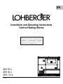
UK Installation and Operating Instructions Central Heating Stoves S o m e i ns tal la ti on a dvi ce g iv e n i n t hi s i ns t ru cti o n m an u al wou ld , i f f ol lo we d, res ul t i n a n i ns tal la ti on t h at m ay n o t m e e t UK b uil di ng re g ul a tio ns . A s up pl e men t a ry i ns t ru cti o n m a n u al is p rov id e d to g iv e c o rrect a dv ic e fo r i ns ta lla ti o ns a n d us e wit hi n th e UK . ZEH 55.4 ZEH 90.4 ZEH 110.4 11-2010 General Information The LOHBERGER Warranty Customer Service or Spare Parts Requirements These warranty conditions are valid in all European countries, in which LOHBERGER stoves are sold. Warranty claims are generally to be directed to your local LOHBERGER dealer, or the dealer from whom you bought the appliance, respectively. Austria (Head Office) Lohberger Heiz u. Kochgeräte Technologie GmbH Landstrasse 19 A-5231 Schalchen Telephone: Telefax: E-mail: DURATION OF THE WARRANTY In principle, LOHBERGER grants a 3-year full warranty on verifiable material or factory defects on every appliance. Warranty expires in any case after five years following the manufacture of the appliance. Certain restrictions apply to some models and parts: for appliances with central heating insert the warranty depends either on the expert installation of a return elevation or the installation of a valve cabinet (AME.4). +43 (0) 7742/ 5211-199 +43 (0) 7742/ 58765-199 [email protected] Our office hours are: Monday to Thursday: from 07.30 a.m. until 12.00 noon / from 1.00 p.m. until 5.00 p.m. Friday: from 0730 a.m. until 1200 noon EXCEPTIONS Exceptions are only parts subject to wear such as fireclay, which is normal for an appliance used for heating. Possibly occurring changes in colour or expansion cracks in the fireclay are dependent on the material and can never be completely ruled out. However, they do not impair the functioning of the appliance as long as the fireclay remains in the firebox. Glass panes (breakage of glass because of external hazard, changes on the surface due to thermal influences such as sintered fly-ash or soot at the surface of the viewing window) Discolouring of paint due to overload or thermal strain. Seals (e.g. hardening or breakage due to thermal or mechanical strain) Surface coatings (frequent cleaning or cleaning with abrasive cleaning agents) Castings which are subject to high thermal stress such as the JETFIRE flame bundling plate and grate. Outside of office hours, please let us know your needs by fax or e-mail. Please note: So that our Customer Service can prepare repairs and spare parts deliveries thoroughly, we require the following information when you request services from us: 1. Your exact address 2. Your telephone and fax number (if available) 3. The exact appliance designation 4. When can our Customer Service call on you? 5. The purchase date 6. An exact description of the problem or the type of service you are requesting START OF WARRANTY The start of warranty is the time the appliance is handed over. Please keep this user manual as well as the warranty card with the invoice in a safe place at all times. A prerequisite of our warranty obligation is that the appliance has been installed and connected according to our instructions and the applicable EN/DIN /Austrian standards and has been operated and expertly maintained according to our instructions. Please have your bill ready at hand In this way you help us to save time and money and also to serve you more efficiently. A Tip: Before setting up and connecting your appliance, write the information on the type plate in the following table! Stove type: Factory number: Nominal heat output in kW with wood/ coal: Radiant heat output in kW with wood/ coal: Required feed pressure in mbar: Flue connection: (left/ right top-back-side) Colour: REPAIRS We will carefully check your appliance and establish whether the warranty claim is justified. If yes, we will decide in which way the defect should be repaired. In the event of a repair we ensure expert performance on location or in our works. This does not affect the start of warranty determined by the handover; if it is necessary to replace the appliance, the warranty period starts anew. If you send in your appliance for repair please enclose your warranty certificate and proof of purchase. ................................................................. ................................................................. ................................................................. ................................................................. ................................................................. ................................................................. COSTS Für die Dauer der Garantie übernimmt Lohberger sämtliche Kosten. Wenn wir entscheiden, dass die Reparatur Ihres Gerätes zweckmäßigerweise in unserem Werk stattfinden soll, dann gehen die Transportkosten sowie die Verantwortung für den Transport zu Ihren Lasten. ................................................................. Important: Please read the information in this manual carefully before you start up your stove for the first time. You will find important information for your safety, for the use, care and maintenance of the appliance,so that you can enjoy your appliance for a long time. LIABILITY EXCLUSION We cannot accept any liability for the loss or the damage of an appliance through theft, fire, vandalism or similar causes. Indirect or direct damages caused by a supplied appliance or resulting upon the delivery of an appliance are excluded from the liability unless the delivery was performed by LOHBERGER or by a transport company commissioned by LOHBERGER. We cannot accept any liability for damages caused by chemical or electrochemical effects (e.g. pollutants in the combustion air, condition of heating water not VDI-compliant – e.g.: “lime deposit”, etc.) or as a result of installation not corresponding to the rules of engineering or the LOHBERGER documentation. We will accept liability for visible paint and enamel damages due to manufacturing defects only if such defects are brought to our attention in writing within 14 days following the handover of the appliance. Should a malfunction occur at some time, please read our Chapter “MalfunctionCauses-Solutions” first. Smaller malfunctions can often be resolved on your own, thereby saving needless service costs. Keep these instructions in a safe place. Should they be lost, we will be happy to send you a new copy. Your locally responsible chimney sweep master should be informed before connecting the stove to the chimney. Changes to or intervention in the appliance through persons not authorized by us to do so will invalidate our warranty obligation. Setting up and conversion work are subject to billing. There is no claim to completeness of the data. We assume no liability. Subject to technical alterations, setting and printing errors! 2 Table of Contents Foreword Page ................................................................................................................................................................................ 4 Important Notes ............................................................................................................................................................................... 4 Safety Instructions................................................................................................................................................................………. 4 Appliance Description .................................................................................................................................................................... 5 Appliance Dimensions…................................................................................................................................................................. 6 Technical Data................................................................................................................................................................................... 7 General Instructions ........................................................................................................................................................................ 7 Assembly and Connection ...............................................................................................................................................….......... 8 Description of the Stove Components and Options........................................……………...................................................... 10 Operating the Stove ............................................................................................................……................................................... 13 Fuels..................................................................................................................................................................................………….... 15 Operating the Stove for the First Time .........................................................................................................………………........ 15 Combustion...................................................................................................................................................................................... 16 Maintenance and Care.................................................................................................................................................................... 16 Malfunction - Cause - Solution ...........................................................................................................……………………............. Examples of Various Installations ...............................................................................……………………………....................... 17 During Assembly and Operation............................................................................................................................................................. Cooking Surface...............................................................................................................………………………………………………….. Oven.........................................................................................................................................................................................………… Flue Connection..................................................................................................................................................................................... Schematic View Flue Connection................................................................................................................................……………......... Flue Connection Conversion.................................................................................................................................................................. Heating Installation Connection ....................................................................................................................……………....................... Connection for the Thermal Safety Valve...............................................................................................................……………….......... Through-Wall Heating........……................................................................................................................................................….......... Through-Wall Heating Dimensions..................................................................................................................................……................ Operating the Through-Wall Heating...........................................................................................................……................................... Stove Cover........................................................................................................................................................……............................. Insulation Cover ..................................................................................................................................................................................... Oven Thermometer.........................................................................................................................................................……................ Oven..........................................................................................…….........................................................................…......................... Oven Door....................................................................................................................................................................................…....... Damper.................................................................................................................................................................................................. Grate..........................................................................................................................................………….............................................. Grate Riddling ....................................................................................................................………………………................................... Cleaning Opening ..................................................................................................................……….................................................... Ash Door Safety Device ...................................................................................................................................……….......................... Primary Air Control…............................................................................................................................................................................. Control Set Screw ..............................................................................................................................................................………......... Secondary Air Control ....................................................................................................................................................….................... Air Bleed Cock........................................................................................................................................................................................ Baffles…............................................................................................................................................................................…………...... Cleaning and Operating Tools .............................................................................................................................................………...... Suitable Fuels ............................................................................................................................................…………………................... Unsuitable Fuels .................................................................................................................................................................................... Prohibited Fuels ..................................................................................................................................................................................... Heating Up Phase....................................................................................................................................................…………................ Adding Fuel .........................................................................................................................................………………………………....... Intake Air Settings...............................................................................................................................……………………………........... Standard Values for Fuel Charge and Duration .................................................................................……………………….................. Steel Cooking Plate .........................................................................................................................……………………………………... 3 4 4 4 8 8 9 10 10 11 11 11 11 11 12 12 12 13 13 13 13 13 13 14 14 14 14 14 15 15 15 15 15 15 16 16 18 Foreword Cooking Surface You have selected a product made by LOHBERGER and therefore Austrian quality. We congratulate you on your choice. LOHBERGER in Schalchen, Austria, has been making a wide variety of appliances for more than 70 years. These appliances are manufactured in traditional high quality, in a timeless, appealing style and colouration, with economical and environment-friendly heating technology, and a high measure of operating comfort. Overheated greases and oils can be self-igniting, prepare all dishes requiring greases and oils, for example, chips, only under constant supervision. Never try to put out grease or oil fires with water! Cover the pot with a lid and pull it from the hot burner. Important Notes Oven Please note that every appliance can only function properly if it is handled correctly and cared for. Following a few important rules is prerequisite to a superior reliability, cost-effectiveness, low-polluting combustion and long life. These are: There is danger of burn injuries when working with the hot oven! Use potholders, insulated mitts or similar. A professional, proper installation Appropriate handling, abiding by the instructions in the Instructions Manual Use of the correct fuels of a sufficient quality and dryness. Regular maintenance and care Running the central heating stove only with a load balance reservoir (min. 500 litres) Operating the central heating stoves with a return by-pass temperature valve (thermal valve, motor-controlled mixing valve, 4way mixing valve). Damage ascribable to the lack of a return bypass temperature valve are excluded from the warranty! Examples of this can be found at the end of these directions. Use caution when opening the oven door. Do not bend over the open oven door immediately. When opening the oven door, a surge of hot air or steam escapes from the opening. Don’t place any aluminium foil or plastics on the cooking surface. Don’t put any combustible or flammable objects on the cooking surface that can pose a danger when the appliance is put into operation. Don’t store any objects in the oven that can pose a danger when the appliance is put into operation. Always make sure the oven door is completely closed when using it to prepare food. Safety Instructions During Assembly and Operation When assembling the stove, work with the operating instructions and observe the individual points. Take the safety clearances into account when assembling the stove. Check the tightness of the stove pipe connection. Inspect the stove for damage (safety glass). Take care that never more wood is laid on than is required for the nominal heat output (ca. 1-1.2 kg) When stoking the fire, open the door slowly, let the exhaust gases be drawn off first. That way you can avoid the exhaust gases escaping into the room. Always use insulated gloves to prevent burn injuries. Please remember that some components of the stove (flue pipe, working door, etc.) get hot during heating and represent a danger of burns. Be especially vigilant that small children are never in any danger! Don’t seal off the stove during heating, there is danger of deflagration. 4 Appliance Description ZEH 55 0010 0022 0024 0030 0040 0100 0110 0120 0130 0150 0180 0190 0280 0320 0330 0355 0370 0390 Base Side panel (with flue con.) Side panel (with flow/return) Cover (enamelled) Cover flow/return Cleaning access panel Wood drawer panel Side panel Oven Cleaning access cover Flue connection piece Oven plain shelf Firebox door protection Grate Front grate Flame bundling plate Damper Heating gas baffles, heating gas plates ZEH 90/ 110 0410 0420 0430 0530 0590 0610 0620 0630 0660 0730 0780 0790 0800 0820 0830 0840 0850 0890 Steel cooking plate Burner cover Water insert cover plate Knob Secondary air lever Control Control switch housing Knob for primary air control Oven hinge Oven door handle Ash scraper All-purpose wrench Grate crank Cover with centre hole Cover w/o centre hole Cover for steel cooking plate Ash pan Burner rope seals 5 0970 0980 1030 1040 1060 1070 1080 1100 1150 1160 1170 1220 9070 9080 9090 9095 Stove edging strip Decorative trim Wood storage drawer Drawer rail Ball latch Thermometer Oven grid shelf Stove frame compl. Heating element, compl. Air bleed cock Adjustable grate, compl. Damper control knob Firebox door compl. Ash door complete Oven door compl. Oven viewing glass, complete Appliance Dimensions ZEH 55 TH Probe fitting ½” female thread THS Therm. safety valve ½” male thread Flow (N/ Q) 5/4” female thread Return (O/ R) 5/4” female thread ZEH 90/ 110 TH Probe fitting ½” female thread THS Therm safety valve ½” male thread Flow (N/ Q) 5/4” female thread Return (O/ R) 5/4” female thread (all measurements in mm) Width Depth Height Base height Base recess Stove frame overhang ZEH 55 ZEH 90 ZEH 110 A B C D E F 550 600 850 100 40 60 900 600 850 100 40 60 1100 600 850 100 40 60 Height Clearance to side Height Clearance to wall Clearance to side Clearance to wall G H I J K L M 145 650 145 650 205 145 175 145 680 120 680 190 145 175 160 680 125 680 195 165 190 Height Flow Height Return Clearance to wall Height Flow Height Return Clearance to side Height N O P Q R S T 727 247 155 727 247 170 617 727 247 155 727 247 170 617 727 247 155 727 247 170 617 Code: Flue connection diameter Flue connection rear Flue connection side Flue connection top Heating connection side Heating connection rear Connections Therm. Safety valve 6 Technical Data Working door opening Charge cavity Oven Steel cooking plate Heating boiler Ash pan Fuel storage drawer Oven plain shelf Oven grid shelf Weight Width x height Width x depth Height (grate top / bottom) width x height x depth width x depth (Part 1) width x depth (Part 2) cooking surface water capacity capacity capacity Width x depth Width x depth Stove without crate Stove with crate ZEH 55.4 ZEH 90.4 ZEH 110.4 mm mm mm mm mm mm m² litres litres litres mm mm kg kg 209 x 154 235 x 403 270 / 420 536 x 473 0,25 22 5 209 218 209 x 154 235 x 403 270 / 420 400 x 220 x 435 627 x 473 256 x 473 0,42 18 5 32 399 x 420 399 x 399 246 258 209 x 154 235 x 403 270 / 420 400 x 220 x 435 772 x 473 311 x 473 0,51 24 5 47 399 x 420 399 x 399 301 316 kW kW kW °C g/s mbar bar °C 19 4 15 290 15,7 0,18 3 95 20 5,9 13,8 246 15,7 0,20 3 95 21 5,5 15,5 246 15,7 0,20 3 95 Output Specifications Data for chimney calculation according to DIN 4705) Nominal heat output total Nominal heat output Flue gas temperature Flue gas mass flow rate Required feed pressure Operating pressure Operating temperature Wood Room Boiler Wood Wood at nominal heat output Max Max General Instructions is possible that the brick clay lining will crack. This, however, doesn’t impair the functioning of the stove. Please note that every appliance can only function properly if it is handled correctly and cared for. Following a few important rules is prerequisite to a superior reliability, cost-effectiveness, low-polluting combustion and long life. These are as follows: Open the damper only for the heating-up phase. Keep the firebox and ash pan doors closed tightly at all times. Avoid overheating the stove, (e.g.: red-hot, glowing steel cooking plate). Damages caused in this manner are not covered by the warranty! The stove must be assembled and connected by a qualified heating specialist and meet the requirements of the valid regulations and provisions applying to the respective installation site. Following the instructions in the Installation and Operating Instructions and having the locally responsible chimney sweep on hand to evaluate the construction or technical conditions. Always ensure that there is an adequate supply of fresh air in the room in which the stove is located! An air exchange of at least 0.8 times per hour by means of a permanent and secure ventilation of the room must be ensured. In the case of tightly closing windows and doors or when other appliances that extract air, such as an exhauster hood, a clothes dryer, a ventilator, or similar, are in the same room in which the stove is located, then it might be necessary to supply combustion air from outside. When operating the appliance and during heating operation, the directions in the Instructions Manual must be followed closely and correctly. Especially the instructions regarding safety and environmental protection are to be carefully observed. If in doubt, consult your chimney sweep! Preferred fuel types are ecological, high-quality and dry. See “Fuels“ on page 14. Every stove requires a certain basic care at regular intervals. Should this not be observed, the likelihood of malfunctions, breakdowns and damage increases automatically and results in annoyance and expense. Parts subject to wear (e.g. seals) or high thermal stress (brick clay, cast parts), or broken stove parts are to be renewed or replaced, respectively, as soon as possible. Heat at low output temperatures in the first 2-3 days. That way the brick lining of the stove will dry out gradually and last longer! If the heating operation is run at a high output during the first few days, it 7 c) The required feed pressure ("chimney draw") Assembly and Connection The feed pressure required for your stove is listed in the table „Technical Data” on page 7 and can be found on the type plate of the stove. It must be ensured that there is enough clearance between all parts of the stove and combustible objects (wood panelling, furniture, curtains, and similar). If there is a wood or synthetic floor, or wall-to-wall carpeting, then a fireproof floor shield made of steel, copper or another non-combustible material must be used. Too low a feed pressure would lead to an incomplete combustion and increased soot and tar formation in the stove and chimney. Too high a feed pressure would accelerate the combustion, cause high flue gas temperatures (damaging the appliance) and greatly increase the fuel consumption. In case of an instalment attached or adjacent to combustible materials or in a kitchen unit, then a fire barrier with min. 50mm (Lohberger BSE 50mm) must be provided. Also when installing the flue pipe, the minimum clearances to combustible materials required by fire police must be observed. Schematic View Flue Connection Ensure a level and vibration-free positioning of the stove. 1. Choose the best flue connection on the stove (rear, side or top) and seal off the unused flue connections tightly. Proper condition of the chimney: Through good thermal insulation, smooth interior surface, tightness. 2. Flue Connection Correct dimensioning of the chimney: Cross-section and effective height must be calculated according to the intended fuels and heat stress. 3. Proper connection of the flue pipe: Tight fit, no cross-section contraction, slight upward inclination toward the chimney, no projection into the chimney. 4. When the chimney is used by more than one appliance: Observe the minimum distance of 60 cm. 5. Unused connection openings are to be sealed off with sealing covers. 6. Sweeping and cleaning accesses, mainly located in cellars or garret storeys, are to be kept closed at all times. Check the seals from time to time, renew when necessary! A trouble-free and economical functioning is ensured when all factors for a thorough combustion are on hand: a) The Chimney The design and condition of the chimney must conform to the regulations valid for the installation location and are to be inspected for defects and flaws before the stove is connected. The effective chimney height from the cooking plate to the chimney outlet must be at least 5 m. If the height is less, the stove must be connected by a vertical flue pipe that is at least 1 m long. A connection to a chimney with an effective height of less than 4 m is not advisable. The chimney should have a unvarying square or round inner diameter and be insulated against cooling. Chimneys made of pre-fabricated assembly units should be preferred. The assessment of the chimney is to ensue according to DIN 4705 Parts 1 and 2, and Part 3 if it used by more than one device. It is absolutely necessary to consult your locally responsible chimney sweep regarding questions of this nature. b) Connection Stove - Chimney The flue pipe is the connection between stove and chimney. When it is being installed, the following should also be observed: The diameter of the flue pipe may not decrease toward the chimney side, the pipe may not project into the chimney. Vertically positioned pipes may not be longer than 125 cm if they are not insulated. Horizontal flue pipe lengths may not be longer than 100 cm without a vertically connected pipe before it. The flue pipe may not descend toward the chimney, but must incline slightly upward toward the chimney. The entire connection between the stove and the chimney must be stable and close fitting. The bond with the masonry of the chimney must be especially durable and tight. 8 Flue Connection Conversion The series stoves are delivered with a screwed-on flue connecting piece in the back panel and can be directly connected to the chimney through an appropriate connecting pipe. Changing the flue connection to the side 1. 2. 3. 4. Remove flue connecting piece from the rear panel Screw off outer cover from the side panel Cut out insulation material Screw off inner cover 5. 6. Screw the included cover (without centre hole) onto the rear panel Screw the flue connecting piece onto the side Changing the flue connection to the top 1. 2. Remove flue connecting piece from the rear panel Screw off the cover on the cooking plate 3. 4. Screw the flue connecting piece onto the cooking plate Screw included cover (without centre hole) onto the rear panel 9 Connection Possibility at the Side Description of the Stove Components and Options VL/ RL downwards Heating Installation Connection The boiler is suitable and approved as a heat generator for warm water heating installations with a flow temperature up to 95°C and a permissible excess operating pressure of 3 bar. In „closed systems“ a thermal safety valve must be attached as security against excess temperature. The relevant connection is located on the back panel of the stove (1/2” male thread). Follow the manufacturer’s instructions when installing. We recommend using our control box type AME for the „closed system“ version. This control box which is only 40 cm wide, contains all instruments you need for operating and regulating the heating system. The safety valves used during installation must be approved (mark of conformity letter “H“!). Their drainage capacity must correspond to the maximum nominal heat output of the boiler. VL/RL towards the back VL/RL upwards Further points to be observed: Heating room guidelines, National building codes, Local building codes, Commercial and fire police regulations, Environmental protection regulations, Regulations of the local power supply company. Connection for Thermal Safety Valve The heat exchanger serves to protect the stove from overheating during a pump standstill and may not be used for preparing water for domestic use! The safety mechanisms must still be accessible after the installation. The runoff must be visible for checking the proper functioning of the thermal safety valve, therefore use the runoff funnel! A trial run must be carried out after completion of the connecting work, during which all control and security instruments are to be adjusted and checked for proper functioning. The assembly, installation, fine-tuning and initial operation with the trial run must be carried out according to the Installation and Operations Instructions by a qualified heating professional! Only then can it be guaranteed that the appliance functions flawlessly. If any damage occurs through omission of any the above points, all warranty claims become null and void. A function check of the thermal safety valve must be carried out at least once a year. To do this, the red cap must be pressed against the valve and water must flow into the runoff funnel. Should the thermal safety valve drip, then the seal and valve seat must be cleaned. The calcification status of the safety devices must also be checked at least once a year. Connection Possibility at the Back Sensor for thermal safety valve with T-piece Thermal safety valve Runoff Supply 10 Safety valve Drain funnel Return valve VL = flow RL = return AE = automatic bleeding SV = safety valve TH = probe fitting Pressure reduction valve with manometer Cold water pipe e r e r r r z ÖNORM B 8131 regulations must be observed when connecting The thei thermal safety valve. o p Cleaning T with angle Stove Cover (Optional) Oven Door (ZEH 90-110) The stove cover serves to cover the cooking surface when the stove is not in use. In this case the flue connection must be connected at the rear or sides (not at the top!). The stove cover is attached by inserting its two hinge pins into the hinge fittings on the stove frame back. The stove cover may not be closed while the stove is in operation! The oven door can be completely removed. This is advantageous for a thorough cleaning of the oven. To cool the oven, the door can be set at a 75-degree angle. To do this, open the door, push the metal clips on the door hinges upwards and close the door to the limit stop. Unhinging the Oven Door Insulation Cover (Optional) The insulation cover is for covering the cooking surface of central heating stoves during operation. When closed, it reduces the amount of radiant heat the stove gives off into the room it is standing in. In this case the adjustable rack must be in the lowest position. The maximum filling height up to the lower edge of the firebox door must be adhered to. Please observe the charge quantity for the different fuels for nominal output according to the table on page 16! The inside of the stove insulation cover has a special heat-deflecting surface coating. When caring for or cleaning, use only gentle (nonalkaline) cleaning agents and no abrasive cleaning utensils. Grease splashes or similar spots should be wiped off with a damp cloth. Don’t let them dry up!. 1. Open the oven door 2. Push up the clips 3. Close oven door to 5mm 4. Lift slightly from this position 5. and pull away and down Oven Thermometer (ZEH 90-110) The thermometer in the viewing glass of the oven door has a reading range of approximately 20 – 300 degrees C. The temperature marks are approximations for baking and broiling/roasting and can deviate slightly from case to case. Hanging the Oven Door Back on its Hinges 1. Insert the hinges into the appropriate openings 2. Open the door slowly and press the clips 3. Arrest with a jerk 4. Close the door and check the correct fit! Oven (ZEH 90-110) The oven has 2 shelf positions and, depending on the stove type, is equipped with a plain shelf and oven grid shelf. It is fully enamelled inside and therefore easy to clean. See instructions for this on page 14. After cleaning, the oven door should be left open a few minutes for airing. The oven must absolutely be pre-heated for baking and broiling/roasting. A brisk fire is required to maintain an oven temperature of around 250 degrees C. Dry, seasoned beech wood is very well suited to this purpose. 11 Cleaning Opening Operating the Stove The cleaning door panel is secured by a ball latch and swings open. The access cover behind it is fastened to the stove front with 2 wing nuts and should be removed to clean the heating flues/draws. Before replacing the cover, check the rope seal of the access cover and replace when necessary. Damper The damper is operated by the knob located in the decorative trim (under the stove frame and opposite the firebox door). Pulling out the knob opens the damper, the heating gases then take the shortest route to the flue pipe. This position may only be selected during the heating-up phase. The damper must be re-closed a few minutes after heating up! When it is closed, the heating gases first circulate around the oven and then escape to the flue. Cleaning door panel Access cover with rope seal Note: An open damper does not result in increased baking strength. In this case the heating gases only brush over the oven surface. In addition, a longer opening of the damper can lead to overheating and therefore to damages to the stove, which are excluded from the warranty. Ash Door Safety Device A bracket is mounted on the inside of the ash door. This means that the ash door can only be opened in connection with the firebox door. This prevents accidental overheating of the stove. For this reason this bracket may not be removed! Grate The adjustable grate (22.5 x 39 cm) is in use in all ZEH stoves. The adjustable grate makes any desired filling cavity height setting possible. The adjustable grate is controlled with the grate crank, which is placed over the lower square-head stud located above the ash pan. Clockwise turning raises the grate. The top grate setting is mainly suitable for cooking and baking, whereby heat output to the heating system is low. Counter-clockwise turning lowers the grate. At the lowest setting, maximum heat output goes to the heating system, the cooking performance is adequate, and the baking/roasting performance is lower. Primary Air Control The amount of combustion air intake and thus the heat output is controlled by the primary air control. It is operated with the control knob on the ash door. In the 0 position the air regulator flap is closed, in every other position (1-6) open to varying degrees. Regular emptying of the ash pan is important, because, for example, a mound of ashes reaching to the grate obstructs the primary air feed. Control knob for primary air Raising and lowering the grate Air control Grate Riddling Primary air To ensure that you have many years of pleasure with your stove, all appliances are equipped with an automatic temperature limiter as standard. This serves to “limit” the combustion air flow rate. However, this has only a limited effect on the output. It is definitely not suitable for compensating excessive fuel charges. A certain amount of fuel will require a certain amount of oxygen for optimum combustion. If the wood is supplied with a lesser quantity of air than is required for clean and efficient combustion, less energy is generated in the appliance (the appliance largely protected from overheating) – the unutilised “wood gas” however escapes through the chimney; the result: low efficiency and high environmental load. Remedy: charge the stove only up to the recommended fuel level. The air entering the fire chamber from below through the grate is responsible for the output since it generates the basic heat resulting in “wood gasification”. Rule of thumb: lots of air from below means lots of combustible wood gas (controllable with the help of the lower rotary knobs on the front). This wood gas is cleanly and efficiently burnt at approximately 950 ºC by means of preheated secondary air (JETIFIRE combustion technology). The secondary air (situated above the firebox door and behind the decorative trim) enters the combustion chamber Removing the ash from the grate takes place from the ash pan cavity side with the grate crank. To do this the grate crank is fitted over the upper square-head stud and turned in any direction. If the grate air vents are heavily clogged or caked with ash or other combustion residues, the grate should be completely removed and cleaned. Grate Riddling 12 through openings in the fire compartment rear wall and from below and above along the fire compartment door over the fuel into the combustion chamber. The exact mixing of the wood gas with hot secondary air ensures optimum combustion – and connected with this, excellent fuel utilisation. The environment will be grateful! Air Bleed Cock The air bleed cock is located on the front panel between the firebox and ash pan doors. To bleed the air from the stove correctly, a repeated deairing procedure is necessary, as the vent connection leads approx. 20 cm upwards and is filled with water. This water must first run off during bleeding. Control Set Screw A change in the air intake cross section can be achieved with the control set screw located on the inside of the ash door. A professional should do this fine-tuning, as several factors must work together to attain an optimum burning process. Screwing in the set screw (about 2 mm), the intake cross section is reduced and a slower, more economical combustion results. When the set screw is screwed out (about 10 mm), the cross section is increased, so that a faster combustion results. Care should be taken that an over-firing doesn’t occur. The draw rate of the chimney can’t be influenced with the control set screw! Air bleed cock Baffles In stoves with an oven (ZEH 90/ 110) there are two baffles installed under the cooking plate, between the oven and the heating element. They direct the heating gases to increased circulation around the oven, resulting in an even distribution of the temperature. Care should be taken that the baffles are correctly replaced after cleaning. Control set screw Baffle Secondary Air Control The addition of secondary air (flowing combustion air from the top, above the fuel) results in a combustion that is attuned to the fuel being used and in low-polluting emissions. The secondary air intake is regulated by the secondary air slider, which is situated above the firebox door and behind the decorative trim. The relevant marks 3-2-1-0 are on the top of the firebox doorframe. Cleaning and Operating Tools Slider position 1 : Required when burning coal or coke. Slider position 2 : For wood burning at partial load operation. Slider position 3 : Max. air intake for wood burning and nominal output operation. Cleaning and operating tools are located inside the swinging side panel of model ZEH 55 and in the storage drawer of the stove in models ZEH 90/ 110. Setting the secondary air lever on the inside of the firebox door is to be undertaken as with the secondary air slider, whereby here the lever position 1 corresponds to the slider position 3 above. ZEH 55 Grate rank Secondary air slider Secondary air All-purpose wrench Ash scraper Secondary air lever 13 Fuels Operating the Stove for the First Time Suitable Fuels After completion of the assembly and connecting work and prior to the start-up, a few measures must still be taken: Firewood Depending on the stove type and outfitting, stove parts, accessories, cleaning and operating tools are stored in the interior of the stove and must be removed be before the first operation. Billet wood should have a maximum water content of 30% of the dry weight, a length of 1/3 m and be chopped or split into smaller pieces. This way they catch fire easily and produce a higher heat output than the same volume of large logs. Roofed over and stored outdoors, whitewood, pine or alder wood should be seasoned a good 2 years, hardwoods even 3 years. Avoid overheating the stove or making the cooking plate glow redhot. Take care that there is a 2mm gap between the steel cooking plate and the stove frame, otherwise a discolouration of the stainless steel stove frame can take place! Gross calorific value of air-seasoned soft woods: 3.19 kWh/ kg Gross calorific value of air-seasoned hardwoods: 4.16 kWh/ kg The significance of the water content in wood in regard to the gross calorific value is shown in the following table: Calorific value Wood storage Water content % kWh/kg 50 2,32 Freshly felled wood 40 2,66 Stored over winter 18-25 3,36 Stored over summer 15-20 4,16 Air-seasoned 10-15 4,63 Seasoned several years Oxygen-rich fresh air is important for an optimum burning process. Therefore aerate the room well before starting the fire. Take care that the heating installation is ready to function (water level, water pressure, temperature, control instruments, safety devices, …) before every start-up! After you have familiarised yourself with the operating procedures for the stove, the first operation can begin. Heating Up Phase Charcoal Briquettes Open the damper Turn the primary air control to position 6 Open the firebox door Set secondary air slider to 0 Crank the grate to the desired position Place 2-3 small wood splints on the grate Spread wood wool or wood chips over them Crumple a little newspaper and place on top Light Close the firebox door Let the wood burn briskly Close the damper Add 2 wood billets Turn primary air control back to position 2 – 3 Adjust the secondary air slider or lever, depending on the fuel type being used The water content of charcoal briquettes is very low, the combustion is very rapid. Calorific value of charcoal: 4.40 kWh/ kg Unsuitable Fuels Damp wood, bark waste, sawdust, wood chips. Use brushwood, wood wool, wood shavings, paper or cardboard only in very small amounts to kindle a fire. The burning of such fuels results in significant pollutant emissions, large amounts of ash, and the heat output is comparatively low. Prohibited Fuels Surface-treated wood (veneered, painted, impregnated, etc.), particleboard, rubbish of any kind (packaging waste), synthetics, newspapers, rubber, leather, textiles, etc. Burning these types of materials burdens the environment seriously and is forbidden by the lawmakers. Furthermore, damage to the stove and chimney can occur. Adding Fuel When adding fuel (stoking) we recommend: Shorter intervals (every 30 – 50 minutes) and smaller amounts. In this way the nominal output is reached, with a lower pollutant emission and superior efficiency. Observe the maximum filling height up to the lower edge of the firebox door! In this case every warranty is rendered null and void! Intake Air Settings The following table shows the recommended intake air settings (after the operating temperature is reached). Partial Load Rated Load (Draw rate 0,09-0,12 mbar) (Draw rate 0,18-0,20 mbar) Fuel Primary Secondary Primary Secondary Whitewood airseasoned Beech wood airseasoned 14 3 2 4 3 3 2 4 3 Standard Values for Fuel Charge and Burn Steel Cooking Plate Time Directions for Caring for and Preserving the Cooking Plate The following table shows the recommended charges for the nominal heat output. Firing Charge Burn time Heat output method Flat firing at highest grate setting 2-3 Wood billets 3 kg ca. 35 min. Nominal output Full firing at lowest grate setting 4-5 Wood billets ca. 6 kg ca. 1,5 hr. Nominal output The bright polished steel cooking plate was oiled before packing for protection from corrosion. First Heating The applied corrosion protection should be wiped off the cooking plate before the first heating. Open a window during the first heating, as the applied corrosion protection develops an unpleasant but harmless smoke and odour for a short time. At the same time, a discolouration typical for steel when subjected to heat occurs on the cooking plate in the area from the hottest place toward the edge. This discolouration will become more even with every further heating! Combustion Cleaning The heating gases are vigorously mixed with the incoming hot secondary air and burn through the flame bundling plate opening in a swirling pattern. The concentrated flames or flame bundling, respectively, cause high temperatures in the firebox (”Hot firebox”) and result in greatly reduced emission values (CO emissions reduced by 90%!) ata shortened heating up phase with longer stoking intervals and to a more effective fuel utilisation (84% fuel utilisation means lower heating costs). The best time to clean the cooking plate when it is still warm after heating. It can be cleaned with commercial powder or fluid scouring agents or the cleaning agent especially for steel cooking plates (Order No. 28999050). Stubborn baked-on residues can be removed with pot scourers or steel wool. Rust spots can only be removed with a wire brush or coarse sand paper. Afterwards, wipe the cooking plate with a damp cloth and let it dry. This is, of course, fastest while the stove is still warm. Finally, grease lightly. Don’t leave any pots or pans on the cold cooking plate. These form „rust rings“ that are difficult to remove! Maintenance and Care Regular maintenance and care are especially important for the stove’s operating safety, cost-efficiency and value preservation. It should be thoroughly cleaned at least 3 x a year. When use is frequent or inferior fuel is used, then correspondingly more often! Preservation Should the stove be left unused for a longer time, then it is advisableto grease the cooking plate with acid-free oil or some margarine after cleaning. Naturally, it should be wiped off the cooking plate again just before the next use! If you follow these instructions, you prevent rust and spot formation on the cooking plate, and the stove keeps its good appearance. Take care that the expansion gaps are always kept clear of encrusted deposits, so that the plate can expand when subjected to heat. Burnedon food or fuel residues in the gaps can cause the steel cooking plate to warp. • Remove and clean the cooking plate, especially the underside with a wire brush. • Flame-bundling plate: Take out the plate and clean by brushing it off. • Remove grate and brush off. Free clogged air vents. • Detach flue pipe(s) and sweep out. • Scrape the firebox walls and gas shaft with the ash scraper. • Brush off damper and holders and check the proper functioning. • Remove and empty ash pan. Sweep out the ash pan cavity. • After removing the cleaning access door, scrape off the reachable heating gas draws with the ash scraper. • Check rope seals on the burners and access cover, replace if needed. • Clean the secondary air vents on the protective firebox door plate with a wire brush. • When cleaning the chrome, anodised or enamel surfaces, use only gentle (non-alkaline) cleaning agents and no abrasive cleaning utensils. The same is valid for cleaning the oven. • When replacing the different stove parts (flue pipe, cooking plate, grate, flame-bundling plate, access door, ash pan), make sure of their correct positioning or tightness. • When replacing the cooking plate, make sure there is a 2 mm wide gap on every side! Where Can the Cleaning Agents be Bought? Stahlfix, Sidol Spezial and Collo profi are available in, for example, department stores (electrical appliance section), electrical appliance shops, chemist’s shops, supermarkets and in shops specialising in kitchens. 15 Malfunction – Cause - Solution A combination of factors is required for a trouble-free operation of the stove: Stove: Correct assembly, connection and start-up. Handling and Care: Regular cleaning of the stove, flue pipe and chimney, according to the instructions in the Instructions Manual. Chimney: Correct dimensioning, flawless condition. Fuel: Use of the recommended types of fuel of an adequate quality and dryness. Weather conditions: No downdraft in the chimney. The following list contains possible problems, their causes and the possible remedies: Malfunction Grate riddling is jammed Possible Cause Solution Ash or combustion residues are jammed in the adjustable grate mechanism: Ash pan is overfull, ash is piled up to the grate: Chimney is still cold or there is stale air in the chimney: Smoke escaping during heating up Temperature is too low (Stove isn’t heating properly) See chapter “Fuels” on page 15. Heating gas draws, connection pipes or chimney is very sooty or displaced: Damper is not open When the flue connection was changed, the original opening was not, or not tightly, sealed off: Wrong intake air setting (too low, air setting not adjusted to the fuel being used): As soon as possible, clean the stove and connection pipes thoroughly, have the chimney swept. Open damper Wrong, too damp or inferior fuel is being used: See chapter “Fuels” on page 15. A too low draw rate in the chimney, frequent occurrence of stale air in the chimney due to weather conditions: Leaks at the connection between stove and chimney, pipe end is not cleanly integrated with the chimney: Have the local chimney sweep examine the chimney in regard to dimensions, condition, tightness. Detach the connection, remove loose mortar, fix the pipe end into the wall, fit the connection pipes in the end pipe with rope sealing. Detach the connection, and replace properly re-aligned or correctly fit together. Thoroughly clean the firebox, ash cavity, heating gas draws and connecting pipes. Have the chimney swept. Connecting pipes are crooked or fit together poorly: Steel cooking plate isn’t in proper position. Steel cooking plate is rusting Empty ash pan, clean the firebox and ash pan cavity. Light a crumpled wad of paper in the stove or chimney and let it burn completely. Smoke-intensive, too damp or inferior fuel is being used: Stove, connecting pipes or chimney are heavily sooted or coated: Open cleaning access opening (cover not screwed on after last cleaning): Temperature is too high (Danger of overheating) Take out the adjustable grate and clean it. Output control is defective. Wrong intake air settings (too high, setting not adjusted to fuel being used): Open firebox and ash door: A too high draw rate in the chimney. Output control at the ash door is defective: Wrong fuel is being used: When there is a film of soot over the entire cooking surface, the humidity in the ambient air can be the cause (steam from the water insert, cooking steam) Rust spots, rust rings come from overflowing pots, food remnants, wet crockery and similar. Screw the cover on tightly See table “Intake Air Settings” on page 15. Screw on the access cover. Re-position correctly, there must be a 2 mm gap between the plate and frame on all sides. Replace the defective output control. See table “Intake Air Settings” on page 15 Close doors immediately. Ask your chimney sweep, possibly install in a flue damper. Replace the defective control. See chapter “Fuels” on page 15 Sand the surface and grease with an alkali-free grease After cooking wipe off the cooking surface and grease it, sand off the rust spots. Don’t use the cooking surface as a storage shelf. See chapter “Stoves with steel cooking plate” on page 15. Max. fill height is up to bottom edge of the fire door! Secondary air plates or JetFire plate is defective Max. charge level not observed Wrong secondary air setting (no secondary air with wood fuel) Oven viewing glass is clouded Overheating of the stove. See Malfunction: ‘Temperature is too high, unhinge the oven door, remove the viewing glass, remove the sealing frame, clean the glass panes. Defective seal Replace sealing frame or viewing glass completely. 16 See table “Intake Air Settings” on page 15 Examples of Various Installations The following pages show schematic diagrams of different system designs. Stop devices, vents and safety devices are not shown. These diagrams are to be understood purely as examples and thus are no substitute for an exact planning, which takes customer-side requirements or hydraulic and safety specification requirements, respectively into account. Return By-Pass Temperature Valve Too low operating temperatures, i.e. flow and return temperatures that are too low, have a significant detrimental influence on the life of the heating stove. When the water dew point is not attained, condensation water, with more or less aggressive chemical components that accelerate corrosion, forms on the surface of the heating boiler. Therefore care must be taken that the return temperature of the heating boiler does not drop below 60°C during continuous running. Temperatures falling below the dew point primarily occurs in low-temperature heating installations (return temperatures down to below 25°C), in installations without a mixer, in the case of extreme light load operation during changes in season and in constant light load operation caused by a stove that is dimensioned too large. Heating flow Heizungsvorlauf Y F Y 3-way thermostat valve (e.g. Overtrop) Setting range 40-70°C Set to 60°C, the return temperature is kept at 60°C. M1 Heating return Heizungsrücklauf M Circulation pump for filling the load balance storage tank 60°C Legend for the Following Hydraulic Diagrams 1 2 3 4 5 ADG Central heating stove ZEH Heating loop Boiler Buffer reservoir Solar model Expansion tank Y1 Y2 Y3 3-way thermal valve Motor mixing organ heating loop Return valve or flap F Temperature sensor 17 M1 M2 M3 Buffer reservoir pump Heating loop pump Boiler filling pump Central Heating Stove with Buffer Reservoir and Integrated Boiler 2 Y3 M2 Y2 M 5 Domestic Brauchwasser water warmwarm Solar Solar model Schema Y3 Brauchwasser Domestic water kalt cold 3 1 4 ADG ADG Y1 F M1 60°C Central Heating Stove with Buffer Reservoir and Boiler (is filled from the buffer reservoir) 2 Y3 Y3 M2 Y2 M3 M 5 Brauchwasser Domestic water warm warm Y3 Solar Solar Schema model ADG 4 1 3 ADG Y1 F M1 60°C 18 Domestic water cold Brauchwasser kalt Central Heating Stove with Buffer Storage and Boiler (is filled from the boiler) 2 Y3 M2 Y2 M 5 Domestic water Brauchwasser warm warm Y3 Solar Schema model ADG M1 4 1 Y3 3 ADG Y1 F M1 60°C 19 Brauchwasser Domestic water cold kalt Assembly and Operating Instructions Central Heating Stoves ZEH Article No.: 54001135 LOHBERGER Heiz u. Kochgeräte Technologie GmbH Landstrasse 19 A-5231 Schalchen Telephone: +43 (0) 7742/ 5211-0 Telefax: +43 (0) 7742/ 5211-201 E-mail: [email protected] Internet : http://www.lohberger.com 20