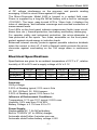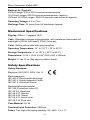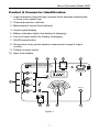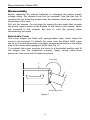
1
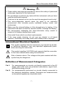
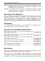
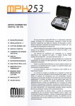
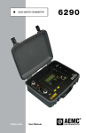
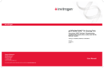
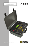
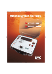
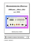
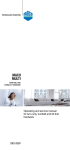
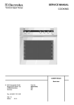
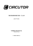
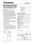
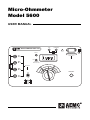
Micro-Ohmmeter
Model 5600
USER MANUAL
®
INSTRUMENTS
LOW
MICRO-OHMMETER MODEL 5600
20 VA
CHARGING
!
FAULT
50/60/400 Hz_110V
300V, CAT II
C1
10A
THERMAL
PROTECTION
P1
mΩ
Rx
30V CAT II
0.1A
0
200 2000
20
20
20
00
µΩ
!
F1
FF
8A 380V
6.3 x 32
200 kA
F2
0
20
-I
A
C2
1
.0
+I
Ω
P2
10
A
1A
ON/OFF
Limited Warranty
The Model 5600 is warranted to the owner for a period of one year from the
date of original purchase against defects in manufacture. This limited
warranty is given by AEMC® Instruments, not by the distributor from whom it
was purchased. This warranty is void if the unit has been tampered with,
abused or if the defect is related to service not performed by AEMC®
Instruments.
For full and detailed warranty coverage, please read the Warranty
Coverage Information, which is attached to the Warranty Registration
Card (if enclosed) or is available at www.aemc.com. Please keep the
Warranty Coverage Information with your records.
What AEMC® Instruments will do:
If a malfunction occurs within the one-year period, you may return the
instrument to us for repair, provided we have your warranty
registration information on file or a proof of purchase. AEMC®
Instruments will, at its option, repair or replace the faulty material.
YOU CAN NOW REGISTER ONLINE AT:
www.aemc.com
Warranty Repairs
What you must do to return an Instrument for Warranty Repair:
First, request a Customer Service Authorization Number (CSA#) by phone or
by fax from our Service Department (see address below), then return the
instrument along with the signed CSA Form. Please write the CSA# on the
outside of the shipping container. Return the instrument, postage or
shipment pre-paid to:
Chauvin Arnoux®, Inc. d.b.a. AEMC® Instruments
15 Faraday Drive • Dover, NH 03820 USA
Tel:
(800) 945-2362 (Ext. 360)
(603) 749-6434 (Ext. 360)
Fax:
(603) 742-2346 or (603) 749-6309
[email protected]
Caution: To protect yourself against in-transit loss, we recommend you
insure your returned material.
NOTE: All customers must obtain a CSA# before returning any
instrument.
Table of Contents
Warning .....................................................................................................3
International Electrical Symbols ................................................................3
Definition of Measurement Categories......................................................3
Receiving Your Shipment..........................................................................4
Packaging..................................................................................................4
Accessories and Replacement Parts ........................................................4
Description ................................................................................................4
Electrical Specifications ............................................................................5
Mechanical Specifications.........................................................................6
Safety Specifications.................................................................................6
Control & Connector Identification ............................................................7
Disassembly ..............................................................................................8
AC Power Selection ..................................................................................9
Indicators.................................................................................................10
Battery Indicators.................................................................................10
Display Indicators ................................................................................10
Fault Indicators ....................................................................................11
Operating Procedure...............................................................................12
Connections and Reading ...................................................................12
Very Low Resistance...........................................................................13
Meter Readings ...................................................................................13
Application Examples..............................................................................14
Measuring Winding Resistance of Motors and Transformers .............14
Measuring Resistance on Electric Motors ...........................................15
Battery Strap Measurements...............................................................16
Maintenance............................................................................................17
Warning ...............................................................................................17
Cleaning...............................................................................................17
Repair and Calibration ............................................................................18
Technical and Sales Assistance .............................................................18
-2-
Micro-Ohmmeter Model 5600
Warning
• These safety warnings are provided to ensure the safety of personnel
and proper operation of the instrument.
• Do not attempt to perform any tests with this instrument until you have
read the instruction manual.
• Tests are to be carried out on non-live and de-energized circuits only!
• The micro-ohmmeter should never be used in an explosive
environment (this includes poorly ventilated battery rooms and
enclosures).
• Make sure the internal battery is fully charged prior to testing. If the
instrument has been unused for several months, recharge the battery.
• We recommend recharging the micro-ohmmeter every month to
ensure a full battery charge when used.
• Only install fuses which are direct replacements.
• If the case needs cleaning, do not use any alcohol or oil based
cleaners. Preferably use soapy water with a damp cloth or sponge.
International Electrical Symbols
This symbol signifies that the instrument is protected by double
or reinforced insulation. Use only specified replacement parts
when servicing the instrument.
This symbol signifies CAUTION! and requests that the user refer
to the user manual before using the instrument.
Risk of electric shock. The voltage at the parts marked with this
symbol may be dangerous.
Definition of Measurement Categories
Cat. I:
For measurements on circuits not directly connected to the AC
supply wall outlet such as protected secondaries, signal level,
and limited energy circuits.
Cat. II: For measurements performed on circuits directly connected to
the electrical distribution system. Examples are measurements
on household appliances or portable tools.
-3-
Micro-Ohmmeter Model 5600
Cat. III: For measurements performed in the building installation at the
distribution level such as on hardwired equipment in fixed
installation and circuit breakers.
Cat. IV: For measurements performed at the primary electrical supply
(<1000V) such as on primary overcurrent protection devices,
ripple control units, or meters.
Receiving Your Shipment
Upon receiving your shipment, be sure that the contents are consistent
with the packing list. Notify your distributor of any missing items. If the
equipment appears to be damaged, file a claim immediately with the
carrier and notify your distributor with a detailed description of any
damage. Save the damaged packing container to substantiate your claim.
Packaging
The Model 5600 Micro-Ohmmeter (Cat. #1431.01) is supplied with a
power supply lead, hex wrench, and user manual.
Accessories and Replacement Parts
Kelvin probes, set of two, on 10 ft color-coded leads with
banana plug terminations..................................................... Cat. #1017.82
Kelvin clips, 1A, set of two, on 10 ft color-coded leads
with banana plug terminations ............................................. Cat. #1017.83
Kelvin clips, 10A, set of two, on 10 ft color-coded leads
with spade lug terminations.................................................. Cat. #1017.84
Fuse, set of 10, 8A, 1¼ x 1/4" fast blow............................... Cat. #2970.13
Battery 6V, 7 Ah rechargeable NiCad.................................. Cat. #2960.12
Soft carrying bag for accessories......................................... Cat. #2119.83
Kelvin Probes 20 ft spring loaded ........................................ Cat. #2118.52
Description
The Model 5600 performs reliable low resistance measurements with
test currents to 10A and resolution to one micro-ohm.
The front end of the Model 5600 employs a four-wire Kelvin
configuration, which eliminates test lead resistance for a measurement
accuracy of 0.25%. A reverse polarity switch compensates for the effect
-4-
Micro-Ohmmeter Model 5600
of DC voltage interference on the accuracy and permits reading
averaging. A built-in circuit filters against AC signals.
The Micro-Ohmmeter Model 5600 is housed in a sealed field case.
Power is supplied by a long-life NiCad battery with a built-in recharger
(110/220V). The large, easy-to-read LCD is 18mm high; it displays the
value of resistance, and indicates overrange and reversed connection of
measurement leads.
Four LEDs on the front panel indicate measurement faults (open circuit,
blown fuse, etc.); thermal protection; low battery and battery recharging.
For operator safety and instrument protection, the micro-ohmmeter is
fuse protected at the inputs. Two fuses, accessible on the front panel,
protect against stored energy in inductive loads.
Enhanced internal circuitry protects against possible inductive kickback
when the current is shut off. A built-in thermal switch protects the microohmmeter against overheating on the 10A range when in continuous
use.
Electrical Specifications
Specifications are given for an ambient temperature of 23°C ± 3°, relative
humidity of 40 to 60% and a supply voltage of 6V ± 0.1V.
Ranges
Display
Resolution
Test Current
2000µΩ
1999
20mΩ
19.99
200mΩ
199.9
2000mΩ
1999
20Ω
19.99
200Ω
199.9
1µΩ
10A
10µΩ
1A
100µΩ
1A
1mΩ
100mA
10mΩ
10mA
100mΩ
10mA
Accuracy:
2000µΩ range:
0.25% of Reading typical, 0.5% max ± 2cts
20, 200, 2000mΩ, 20, 200Ω ranges:
0.25% of Reading typical, 0.5% max ± 1ct
Influence of Environment Conditions:
Temperature: 0.1% per 10°C typical, 0.25% max.
Humidity: 0.5% max from 10 to 90%
Battery Voltage: ± 0.1% from 4.5 to 7V
Power Supply:
Rechargeable 6V, 7 Ah NiCad battery;
Built-in 110/220V (47 to 450Hz) charger;
Automatic shutoff after 4 minutes non-use;
Automatic shutoff when battery voltage <4.5V
-5-
Micro-Ohmmeter Model 5600
Battery Life (Typical):
2000µΩ range: 200 to 300 8-second measurements
20-200mΩ ranges: 900 30-second measurements (approx)
2000mΩ, 20-200Ω ranges: 5000 30-second measurements (approx)
Operating Voltage: 4.5 to 7VDC
Recharge Time: 14 hours from full discharge (approx)
Mechanical Specifications
Display: 2000ct, 7 segment LED
Case: Fiberglass-charged polycarbonate, with handle and removable lid,
watertight to IP534 (lid closed), IP520 (lid open).
Color: Safety yellow case with gray faceplate
Operating Temperature: 14° to 131°F (-10° to 55°C)
Storage Temperature: -4° to 131°F (-20°C to 55°C)
Dimensions: 15.35 x 10.24 x 9.84" (390 x 260 x 250mm)
Weight: 17 lbs 10 oz (8kg approx) without leads
Safety Specifications
Safety Standards:
Electrical: EN 61010, 300V, Cat. III
Electromagnetic:
IEC 801-2, Electrostatic discharge
IEC 801-3, Electromagnetic Fields
IEC 801-5, Electrical shocks
Mechanical/environmental:
IEC 529, Protection Index (IP)
IEC 68.2.6, Vibrations
IEC 68.2.27, Shocks
IEC 68.2.29, Shake
IEC 68.2.31, Knock over
IEC 68.2.32, Drop test
Case Material: UL 94
Overload Input Protection: 380Vrms
Fuses: Two high interrupting capacity, 8A, 380V, 1¼ x ¼"
-6-
Micro-Ohmmeter Model 5600
Control & Connector Identification
1. Lead connection terminal lugs; accepts 4mm diameter banana jack
or 6mm (min) spade lugs.
2. Thermal protection indicator
3. Measurement current fault indicator
4. Liquid crystal display
5. Battery indication lights (low battery & charging)
6. Line cord input socket for battery recharging
7. On/Off power button
8. Six-position rotary switch selects measurement range & output
current
9. Polarity inverter switch
10. Input fuse holders
2
®
INSTRUMENTS
3
5
4
LOW
MICRO-OHMMETER MODEL 5600
6
20 VA
CHARGING
!
FAULT
50/60/400 Hz_110V
300V, CAT II
C1
10A
THERMAL
PROTECTION
P1
mΩ
Rx
30V CAT II
1A
20
00
µΩ
0.1A
200 2000
20
0
1A
.0 00
2
+I
C2
20
Ω
P2
10
A
1
ON/OFF
-I
!
F1
FF
8A 380V
6.3 x 32
200 kA
10
F2
9
Figure 1
-7-
8
7
Micro-Ohmmeter Model 5600
Disassembly
Before replacing the internal batteries or changing the power supply
voltage rating, the chassis must first be removed. Use the hex key to
unscrew the six fastening screws from the chassis, which are located on
the bottom of the case.
Pull out the chassis. Do not forget to unplug the two leads that connect
the power supply board in the bottom of the case to the boards, which
are mounted in the chassis. Be sure to note the polarity when
reconnecting the leads.
Detachable Cover
The cover hinges are fitted with spring-loaded clips, which allow the
cover to be removed. To detach the cover from the Model 5600, open
the lid to a horizontal position and apply downward pressure to the hinge
side of the cover while gripping it firmly (see Fig. 2).
To re-attach the cover, position the cover in a horizontal position and fit
the hinges into the respective housing. Apply strong rear-to-front
pressure to the cover until it snaps into place.
Unhinging
F
F
Supporting Point
Figure 2
-8-
Micro-Ohmmeter Model 5600
AC Power Selection
The Model 5600 may be recharged by 110V or 220VAC (47 to 450Hz).
The instrument includes a 110V supply cord, which provides the
charging voltage for the rechargeable battery. Verify that “110V” appears
on the indicator located below the line cord indicator socket on the front
panel; this will permit recharging with the 110V supply cord.
To change the charging voltage, disassemble the unit as previously
noted. Move the switch on the power supply board to the “220V” position
(see Fig. 3). A 220V supply cord (not supplied) is required for 220V
operation. Be sure to change the indicator on the front panel to the
“220V” position by removing the two screws that secure it and turning the
indicator over.
Source Voltage Selection
Switch (110V AC/220V AC)
Power Supply Board
110V
220V
6V
10 A
6 V DC
Supply Fuse
Figure 3
CAUTION: Do not change the charging voltage while the Model
5600 is connected to the AC supply.
-9-
Micro-Ohmmeter Model 5600
Indicators
Battery Indicators
• LOW - When flashing, indicates battery life is sufficient for 10
measurements at 10A and more than 100 measurements for other test
currents. When the flashing stops, the instrument no longer has
sufficient power to perform any further tests. Recharge the batteries.
• CHARGING - The green charging light indicates that the battery is
currently being recharged. This indicating light will remain on as long
as the instrument is connected to AC supply.
Display Indicators
• “1” - On the left of the display indicates range overload.
• “—” - On the left of the display indicates a reversed connection of the
measurement leads (crossing the voltage and current leads).
®
INSTRUMENTS
LOW
MICRO-OHMMETER MODEL 5600
20 VA
CHARGING
!
FAULT
50/60/400 Hz_110V
300V, CAT II
C1
10A
THERMAL
PROTECTION
P1
mΩ
Rx
30V CAT II
0.1A
0
200 2000
20
20
µΩ
!
F1
FF
8A 380V
6.3 x 32
200 kA
F2
Figure 4
- 10 -
0
20
-I
A
C2
1
.0
+I
Ω
P2
10
A
20
00
1A
ON/OFF
Micro-Ohmmeter Model 5600
Fault Indicators
• FAULT - The fault light will illuminate in one of two cases:
1. If the measured resistance is very high in relation to the range.
Switching to a higher range will extinguish the light.
2. If the current output is zero, due to an open circuit or blown fuse.
Check the circuit for probe/clip contact on test sample and
condition of fuses.
• THERMAL PROTECTION - On the 2000µΩ range (10A), thermal
protection of the instrument is provided by an internal thermostat
which interrupts the 10A current during prolonged operation. When
overheated, the thermal protection circuit turns on its respective
indicator light and disables the 10A, 2000µΩ range. The other ranges
may still be used during this condition.
NOTE: To make a rapid test of the internal fuses, short-circuit terminals
C1 and C2. Switch on the instrument using the On/Off button. If the
“Fault” light comes on, at least one of the two fuses is blown.
Warning
When using 20 ft spring loaded Kelvin lead (Cat.# 2118.52) on
the 10A range, the fault light may stay on all the time.
Measured values are good.
- 11 -
Micro-Ohmmeter Model 5600
Operating Procedure
Before performing the resistance test, verify that the sample under test is
not energized.
Connections and Reading
Clean all surfaces before connecting test leads. Verify a solid connection
between test leads and the sample. Set the On/Off button to the ON
position and select the range that provides the most stable reading. If the
anticipated resistance is not known, begin with the highest range (200Ω)
and successively lower the range selection until adequate resolution is
achieved. The range selection may be changed while the instrument
remains energized.
Read the displayed resistance value directly. The use of a Kelvin
connection eliminates test lead resistance, as shown in Figure 5.
®
INSTRUMENTS
MICRO-OHM
C1
P1
Rx
P2
C2
-I
!
F1
I
U
Figure 5
- 12 -
Micro-Ohmmeter Model 5600
Very Low Resistance
When measuring very low resistive values (2000µΩ range) the presence
of stray DC currents may affect the accuracy of the measurements.
These currents can be present due to a variety of reasons including
chemical or thermal EMF in samples made of dissimilar metals. You can
eliminate the effects of this by reversing the direction of current flow
(inverter switch, see Figure 6) and using the average of forward and
reverse readings. A minus sign will appear in the display when the switch
is in the reverse position. Disregard this sign when calculating the
average values.
The presence of AC interference in the sample under test may cause the
measured value on the display to fluctuate. This interference may
become more noticeable in the presence of strong electric fields. The
effects of this interference may be reduced by twisting the leads
together.
+I
–I
Figure 6
Meter Readings
When testing resistive samples, the meter reading will stabilize within the
first few seconds. On inductive loads (e.g. transformers), the
measurement reading may take from several seconds to a few minutes
to stabilize and depends greatly on the type of equipment and the
impedance of the equipment under test. On very large samples such as
utility transformers, 10 to 15 minutes charging time may be necessary.
- 13 -
Micro-Ohmmeter Model 5600
Application Examples
The Model 5600 performs reliably on a variety of low resistance
situations. Typical applications include:
• Contact resistance of breakers and switches
• Wire to terminal connections
• Winding resistance
• Motors and generators
• Aircraft and rail bonds
• Grounding connections
• Many other very low resistance samples
The proper procedures for using the Model 5600 in some specific
applications are outlined below.
Measuring Winding Resistance of Motors and Transformers
CAUTION: Prior to and after testing a transformer winding, the
energy stored in the magnetic field must be dissipated by shorting the
transformer terminals. For additional safety, the transformer terminals
should be jumpered together before the instrument is disconnected.
One terminal of the sample should be grounded for safety!
Make connections to the transformer as shown in Figure 7. On larger
transformers, the measurement stabilization time will increase.
®
INSTRUMENTS
MICRO-OHM
C1
P1
Rx
P2
C2
–I
!
F1
Figure 7
- 14 -
Micro-Ohmmeter Model 5600
Measuring Resistance on Electric Motors
For this test, Kelvin probes should be used (Figure 8). Make contact with
each segment on the motor commutator. Allow approximately two
seconds for the display to stabilize.
®
INSTRUMENTS
MICRO-OHM
C1
P1
Rx
P2
C2
–I
!
F1
Figure 8
- 15 -
Micro-Ohmmeter Model 5600
Battery Strap Measurements
Proper battery strap resistance measurements will help ensure proper
voltage output. The resistance on battery strap connections should be
measured using the Kelvin probes (see Figure 9). Measurements must
be made with the system power turned off.
The average resistance of all the intercell connections should be
determined by totaling the individual resistances and dividing by the
number of connectors. Each individual cell resistance should not exceed
the average by more than 10%. See the manufacturer's specifications for
typical resistance values.
®
INSTRUMENTS
MICRO-OHM
C1
P1
Rx
P2
C2
Battery
–I
Battery
!
F1
Figure 9
- 16 -
Micro-Ohmmeter Model 5600
Maintenance
Warning:
• For maintenance use only original factory replacement parts.
• To avoid electrical shock, do not attempt to perform any servicing
unless you are qualified to do so.
• Do not perform any service while the micro-ohmmeter is on any circuit.
• To avoid electrical shock and/or damage to the instrument, do not get
water or other foreign agents into the electronic module.
• Make sure the internal battery is fully charged prior to testing. If the
instrument has been left unused for several months, recharge the
battery.
• We recommend recharging the micro-ohmmeter every month to
ensure a full battery charge when used.
• When replacing
replacements.
fuses,
install
only
fuses
which
are
direct
Cleaning
• If the case needs cleaning, do not use any alcohol or oil based
cleaners. Preferably use soapy water with a damp cloth or sponge.
• Dry immediately after cleaning. Avoid water penetration into the
electronic module.
• Make sure the micro-ohmmeter and all leads are dry before further
use.
- 17 -
Micro-Ohmmeter Model 5600
Repair and Calibration
To ensure that your instrument meets factory specifications, we recommend
that it be submitted to our factory Service Center at one-year intervals for
recalibration, or as required by other standards or internal procedures.
For instrument repair and calibration:
You must contact our Service Center for a Customer Service Authorization
number (CSA#). This will ensure that when your instrument arrives, it will be
tracked and processed promptly. Please write the CSA# on the outside of
the shipping container. If the instrument is returned for calibration, we need
to know if you want a standard calibration, or a calibration traceable to
N.I.S.T. (includes calibration certificate plus recorded calibration data).
Chauvin Arnoux®, Inc.
d.b.a. AEMC® Instruments
15 Faraday Drive
Dover, NH 03820 USA
Tel:
(800) 945-2362 (Ext. 360)
(603) 749-6434 (Ext. 360)
Fax:
(603) 742-2346 or (603) 749-6309
[email protected]
(Or contact your authorized distributor)
Costs for repair, standard calibration, and calibration traceable to N.I.S.T. are
available.
NOTE: All customers must obtain a CSA# before returning any
instrument.
Technical and Sales Assistance
If you are experiencing any technical problems, or require any assistance
with the proper operation or application of your instrument, please call, mail,
fax or e-mail our technical support hotline:
Chauvin Arnoux®, Inc.
d.b.a. AEMC® Instruments
200 Foxborough Boulevard
Foxborough, MA 02035, USA
Phone: (800) 343-1391
(508) 698-2115
Fax:
(508) 698-2118
[email protected]
www.aemc.com
NOTE: Do not ship Instruments to our Foxborough, MA address.
- 18 -
Chauvin Arnoux®, Inc. d.b.a AEMC® Instruments
15 Faraday Drive • Dover, NH 03820 USA
www.aemc.com
99-MAN 100040 v10 04/07