1
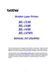
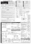
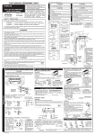
THE CHOICE OF MOUNTING SITE (Please note the following matters and obtain permission from customer before installation).
FOR SERVICE PERSONNEL ONLY
Tools Needed For Installation Work
●
●
Pipe Cutter
●
●
Vinyl Tape
●
Pliers
Flare Tool
Qty
2
1
2
Binder
4
AAA Size Battery
2
Please request your sales agent or qualified technician to install your unit. Water leakage, short circuit or fire may occur if you do the installation work yourself.
●
Make sure that the units are mounted at locations which are able to provide full support to the weight of the units. If not, the units may collapse and impose
danger.
●
Observe the rules and regulations of the electrical installation and the methods described in the installation manual when dealing with the electrical work. Use
power cables approved by the authorities of your country.
●
Be sure to use specified wire for the connection indoor and outdoor units. Please ensure that the connections are tight after the conductors of the wire are
inserted into the terminals. Improper insertion and loose contact may cause over-heating and fire.
Air inlet
Air
outlet 1000 mm
or more
Air
1000 mm outlet
or more
5
Air inlet
Air
outlet
1000 mm
or more
Screw for holder of Remote
Controller
(3.1x16)
Air
outlet
1000 mm
or more
2
Insulation pipe for drain pipe
1
6
Be sure to
completely
seal any
gap with
putty.
Insulation pipe
7
1
Please use the specified components for installation work. Otherwise, the units may collapse or water leakage, electric shock and fire may occur.
●
When installing or removing an air conditioner, only specified refrigerant (R410A) shall be allowed, do not allow air or moisture to remain in the refrigeration
cycle. Otherwise, pressure in the refrigeration cycle may become abnormally high so that a rupture may be caused.
●
Be sure to ventilate fully if a refrigerant gas leak while at work. If the refrigerant gas comes into contact with fire, a poisonous gas may occur.
●
After completion of installation work, check to make sure that there is no refrigeration gas leakage. If the refrigerant gas leaks into the room, coming into
contact with fire in the fan-driven heater, space heater, etc., a poisonous gas may occur.
11
Unauthorized modifications to the air conditioner may be dangerous. If a breakdown occurs please call a qualified air conditioner technician or electrician.
Improper repairs may result in water leakage, electric shock and fire, etc.
Piping shall be suitable supported with a maximum spacing of 1m between the supports.
●
Do not install the unit near a location where there is flammable gas. The outdoor unit may
catch fire if flammable gas leaks around it.
●
For installation of front panel RAI-ECPM, please follow exactly the instruction in the manual.
●
Please ensure smooth flow of water when installing the drain hose.
115mm or less
650 (Panel)
42
393 (Elec-box)
580 (Indoor unit)
600 (Opening on ceiling)
610 (Suspension bolt)
●
●
112 62
227 (Electric box)
230 (Drain)
Drain outlet
●
32
55
285
65
42
INDOOR UNIT
Insert 980 ~ 1470N
(100 ~ 150kgf)
Concrete
Bend slippreventive metal
110
●
Suspension
bolt (M10)
WALL
●
Be sure that bottom face
of indoor main unit is the
same height (or expected
height if the ceiling is new
construction.) as lower
surface of the ceiling.
(2) Stick out above 0mm
! CAUTION
●
●
Be sure to install the indoor unit level. If the indoor unit is
inclined, water may leak.
If space between bottom surfaces of indoor unit and ceiling
is not correct, there may be a gap between the panel and
indoor unit, with consequence dropping of condensed water.
If constructing the ceiling after installation
of air conditioner, be sure to attach a
pattern paper for installation that shows
ceiling opening dimension.
Pattern paper for
12
installation plate
Installation plate
13
fixing screw
Selecting the switch
1 Turn power off.
2 Remove cover of the electrical box.
3 When install the indoor unit 2500mm
or more from the floor, select the
“STATIC PRESSURE SW” on the main
PWB to HIGH PRESSURE.
PATTERN PAPER FOR INSTALLATION
400mm (Suspension bolt)
Marking hole for
opening on ceiling
Center of
indoor unit
Fixing hole
for panel
Drain Pipe
600mm (Opening on ceiling)
! WARNING
●
Use PVC pipe VP20 (O.D. 26mm) for drain pipe.
Be sure to roll an insulation (thickness 10mm or more) for the drain pipe at indoor side.
Always draw the drain pipe downward so that water flows smoothly. Fix it (ex. by hanger)
to prevent a peak and trap.
! CAUTION
When connecting pipes, if flare nut is over-tightened at the small diameter side, the screw
thread of the service valve may be broken making pipe connection impossible. Be sure to
tighten the nut with specified torque.
! CAUTION
●
Wrench
Torque
wrench
To be
adhesion
Refrigerating pipes with insulation
(purchased in the field)
Binder 2 encroach (2 ~ 4mm)
To be adhesion
PVC adhesive
Securely glue connection part of drain
hose and PVC pipe, using PVC
adhesive.
● If gluing of drain hose and PVC pipe
is too weak, water leakage may occur.
Be sure to wrap generally-available
insulator (10mm or more of foamed
polyethylene) around drain hose,
inside the house, for insulation heat.
● Checking drain and water leakage.
Perform after connecting power.
● If checking of drainage is omitted,
water drop may occur.
● Add water to water pan of indoor unit
as shown below.
● Perform test running of drain pump to
check drainage operation.
● Test run method
1 Turn power on.
2 Remove cover of electric box and
set the drain pump test run switch
to TEST.
3 After checking the drainage, return
the switch to NORMAL.
HIGH PRESSURE
Drawing of bottom view of ceiling
NORMAL
Selecting the Mounting Position
STATIC PRESSURE SW
This is used for increasing fan speed
according to the situation of the trial
operation inside the room with ceiling
height of 2.5m and above.
However noise gets slightly higher.
The installation place is very important for the air conditioner because it is very difficult to
move from one place to another after the first installation.
Decide the mounting position together with the customer.
The discharge direction can be selected as shown below.
1000mm or more
600mm or more
600mm or more
Pipe
3 Directions
3 Directions
2 Directions
2 Directions
Since 2-way outlet as shown below causes performance problems, do not set it.
Trap
! CAUTION
●
No insulation
Pipe
Pipe
If drain pump test run is right set
to TEST, drain pump may
malfunction.
Insulation pipe
(10mm or more of
foamed polyethylene)
(purchased in the field)
PVC pipe
(purchased in the field)
Insulation pipe
for drain pipe 6
●
Ditch
<IA370: A >
Rubber strap tied with great force
Pipe
Connecting of drain pipe
! CAUTION
Stagnant
water
Insulation pipe for
flare section 1
Indoor unit
Pipes
600mm or more
The rubber strap used for fixing the insulator
should not be tied with great force. Otherwise,
this will damage heat insulation and causes
water condensation.
Wrapping
Insulation at indoor unit
Seal
Insulation (Thickness
10mm or more)
Flare nut
Union
Indoor unit
NOTE
Please using this pattern paper, decide the suspension
bolt. Position by putting this reverse side on ceiling surface.
4 Directions
Downward 1/25 ~ 1/100
Connecting the pipe
Remove the flare nut and seal cap.
By loosening the flare nut at the pipe end, the refrigerant is discharged in a small amount.
The arrangement has been made for shipment, and the discharge of refrigerant is never a
trouble to the equipment.
When the flare nut is removed, never fail to remove the seal cap. If not removed, the refrigerant
will not be circulated, which result the compressor drive motor will possibly be burnt.
Apply refrigerator oil to the union and the flared portion of the pipe.
Wrap flare insulation, bind top and bottom flare insulation by binder.
580mm (Indoor unit shape)
600mm or more
●
NOTE:
During 2 directions or 3 directions, sound level will increase.
When install the indoor unit below than
2500mm from the floor, select the
“STATIC PRESSURE SW” on the main
PWB to NORMAL.
600mm (Opening on ceiling)
! CAUTION
(3) Draw in above 3mm
Drain pipe installation
●
NORMAL
AIR FLOW
SELECTION
Connecting the pipe to the indoor unit
0~2
(1) Same level (draw in 0~2mm)
Be sure that the wire is not
in contact with any metal in
the wall. Please use the
protection pipe as wire
passing through the hollow
part of the wall so as to
prevent the possibility of
damaged by mouse.
Be sure to use protection pipe
(commercial product).
If connecting cables are touching
metal lath inside the wall or inside
the wall is hollow where mouse
can bite cables, it can cause
electrical shock or fire.
If sealing is not complete, high
humid air from inside the wall or
outside of the room can come in
and cause water dripping.
Sleeve of
protection
pipe
3WAY
A
Corner seal 16
4
Be sure to install the indoor units as follow position (1).
Do not install the indoor units as follows position (2) (3).
H beam
Suspension
bolt (M10)
Drill a ø 65mm hole on wall which is slightly tilted towards
the outdoor side. Drill the wall at a small angle.
Cut the protection pipe according to the wall thickness.
Empty gap in the sleeve of protection pipe should be
completely sealed with putty to avoid dripping of rain
water into the room.
Protection
pipe
Drawing of
bottom view of
ceiling
Indoor unit
●
Wall Penetration and Installation of Protection Pipe
2 ~ 5mm
A-A Section view
Selecting the switch
1 Turn power off.
2 Remove cover of the electrical box.
3 When selecting discharge direction of 2 directions or 3 directions, select
the “AIR FLOW SELECTION” on the main PWB to 3 way.
610mm (Suspension bolt)
Seal with
putty
Blower cover
When selecting discharge direction of 4 directions, select the “AIR FLOW
SELECTION” on the switch PWB to NORMAL.
Suspension
bolt (M10)
Ceiling
Outdoor
Corner seal 16
Corner seal 16
Washer (Local
purchase)
Long nut
About 75
110
About 75
Fit the blower cover.
Suspension bolt (M10)
(Local purchase)
Hexagon nut (M10)
(Local purchase)
C type
metal
Nut
Seal with putty
Corner seal installation
Install the corner seal at position shown. Fix the corner seal certainly. Shall be installed
disregard to 2 directions, 3 directions or 4 directions.
VP20
The space between bottom surfaces of ceiling and indoor unit
Suspension bolt (M10)
Angle
Indoor
Blower cover installation
Install the blower cover only to the air outlet direction which is not in use.
Install the blower cover at the diffuser position shown. Fix the blower cover certainly.
Set nut and washer on suspension bolt and hook it to suspension clamp by lifting the indoor
unit.
Suspension bolt must have play of 20-30 mm on its right and left. If cannot have enough
play, fix lifting lug to suspension bolt without attaching nut underneath the suspension bolt,
then attach nut and install indoor unit.
Make sure that indoor unit is kept level using a level.
Air outlet
●
Ceiling
●
1
2 direction example
Pattern paper for positioning plate 11
Hanger bolt
●
17
A
Air inlet
Angle
●
Drain Pipe
Must be installed separately.
Insulate indoor part of pipe to
prevent condensation.
Qty
Blower cover 14
150 ~ 160mm
Suspension
bolt (M10)
Item
3 Installation of indoor unit
Reinforcing
bar
Angle
between the indoor and
outdoor unit should be kept
below 10m.
● The connecting pipe, no
matter big or small, should all
be insulated with insulation
pipe and then wrapped with
vinyl tape. (The insulator will
deteriorate if it is not wrapped
with tape).
VP20
Be sure to reinforce furring of ceiling (frame : ceiling joints and supporter) to maintain level
of ceiling and prevent vibration of ceiling plate.
Suspension bolts should be purchased in the field.
Refer to diagrams shown below for length of suspension bolts.
● In case of steel frame
In case of wooden frame
(Unit : mm)
Nut
● The difference in height
Insulator
3
In case drain piping cannot be done smoothly due to obstacles, it can also be arranged
outside of the main unit as shown in the drawing below.
Need a connecting work for refrigerant pipe, drain pipe and F cable in the ceiling after
suspending the indoor unit. Arrange drain pipe, refrigerant pipe and F cable in their installation
position.
For finishing of opening on ceiling, arrange with builder in detail.
If ceiling is already completed, connecting cables between indoor and outdoor, piping and
drain piping must be done before fitting indoor unit.
60 ~ 90mm square piece of lumber
No.
Insulation (Thickness 10mm or more)
Narrow pipe Ø6.35
Wide pipe Ø12.7
Above 300
110
●
RAI-50NH5A
Corner Seal
16
(Unit : mm)
Installation of suspension bolts
●
2
150mm or less
Downward pitch 1/25 ~ 1/100
Use PVC pipe VP20
2 Preparation for installing indoor unit
●
4
(M5 X 16)
Blower cover
●
Air outlet
●
1
14
97 (Drain)
●
Pattern paper for installation
plate
64
Panel (Optional part RAI-ECPM)
Ceiling
1
Installation plate fixing screw
●
●
Pattern paper for positioning
plate
13
A circuit breaker or fuse (16A time delay) must be installed. Without a circuit breaker or fuse the danger of electric shock exists.
A main switch with a contact gap of more than 3.5mm has to be installed in the power supply line to the outdoor unit.
●
12
CAUTION
●
650 (Panel)
600 (Opening on ceiling)
580 (Indoor unit)
400 (Suspension bolt)
1
8
Be sure to use the specified piping set for R-410A. Otherwise, this may result in broken copper pipes or faults.
1 Opening on ceiling and suspension bolt
The indoor piping
should be insulated
with the enclosed
insulation pipe. (If the
insulator is insufficient,
please use commersial
products).
Remote Controller
●
!
! CAUTION
• The installation height of indoor unit
must be 2.3m or more.
1
3
4
Please observe the instructions stated in the installation manual during the process of installation. Improper installation may cause water leakage, electric
shock and fire.
Figure showing the Installation of Indoor Unit.
Holder for Remote Controller
WARNING
●
●
Item
Insulation pipe for flare section
CAUTION ......... Improper installation may result in serious consequence.
!
●
●
●
No.
Be sure that the unit operates in proper condition after installation. Explain to customer the proper way of operating the unit as
described in the user’s guide.
●
●
●
Names of Indoor Components
Read the safety precautions carefully before operating the unit.
The contents of this section are vital to ensure safety. Please pay special attention to the following sign.
! WARNING ........ Incorrect methods of installation may cause death or serious injury.
!
CAUTION
!
STATIC PRESSURE
●
No nearby heat source and no obstruction near the air outlet is allowed.
The clearance distances from top, right and left are specified in figure below.
The location must be convenient for water drainage and pipe connection with the outdoor unit.
To avoid interference from noise please place the unit and its remote controller at least 1m from the radio, television and inverter type fluorescent lamp.
To avoid any error in signal transmission from the remote controller, please put the controller far away from high-frequency machines and high-power wireless
systems.
The installation height of indoor unit must be 2.3m or more.
●
SAFETY PRECAUTION
●
●
AIR FLOW SELECTION
R410A
●
The unit should be mounted at stable, non-vibratory location which can provide full support to the unit.
Evaporator
Air outlet
Water pan
Pitcher
(add water)
TEST
DRAIN PUMP TEST SW
HFC
+ – Screwdriver ● Measuring Tape ● Knife ● Saw
ø 65mm Power Drill ● Hexagonal Wrench Key (
4mm)
Wrench (14, 17, 19, 22, 26, 27mm) ● Gas Leakage Detector
●
RAI-25NH5A
RAI-35NH5A
RAI-50NH5A
●
2500mm
or more
HITACHI CEILING CASSETTE-UNIT AIR
CONDITIONER INSTALLATION MANUAL
INDOOR UNIT
●
Indoor Unit
! WARNING
Carefully read through the procedures of proper installation
before starting installation work.
The sales agent should inform customers regarding the correct
operation of installation.
300mm
or more
●
NORMAL
DRAIN PUMP
TEST SW
Preparation of Pipe
2
Use a pipe cutter to cut the copper pipe.
●
●
Trimming tool
Removal Of Air From The Pipe And Gas Leakage Inspection
Procedures of using Vacuum Pump for Air Removal
Please be careful when bending the copper pipe.
Applied frozen grease to the connection points and then screw in
manually. After that, use a torque wrench to tighten the connection.
Flare nut
1
Copper pipe
Wrench
Torque
wrench
! CAUTION
●
●
●
Jagged edge will cause leakage.
Point the side to be trimmed downwards during trimming to
prevent copper chips from entering the pipe.
Outer
dia.of pipe
Torque N·m
(kgf · cm)
Small dia. side
6.35 (1/4")
13.7 – 18.6 (140 – 190)
Large dia. side
Before flaring, please insert the flare nut into the pipe.
Die
Die
Valve
head cap
A
9.52 (3/8")
34.3 – 44.1 (350 – 450)
Small dia. side
6.35 (1/4")
19.6 – 24.5 (200 ~ 250)
Large dia. side
9.52 (3/8")
19.6 – 24.5 (200 ~ 250)
12.3 – 15.7 (125 ~ 160)
Valve core cap
Copper pipe
As shown in figure on the right, remove the cap of valve head
and valve core and then connect them to the vacuum pump
and manifold valve.
For R410A tool
Meter showing pressure
R410A
Manifold valve
2
Lo
Fully tighten the “Hi” shuttle of the manifold valve and completely
unscrew the “Lo” shuttle. Run the vacuum pump for about
10–15 minutes, then completely tighten the “Lo” shuttle and
switch off the vacuum pump.
Hi
Charge hose
Valve
Valve
Vacuum
pump
Vacuum pump
adapter
3
4
Completely unscrew the spindle of the service valve (at 2 places)
in anti-clockwise direction to allow the flow of coolant (using
Hexagonal Wrench key).
When pumping starts, slightly loosen the
flare nut to check of air sucked in. Then
tighten the flare nut.
Remove the Charge hose and tighten the cap of valve head.
The task is then completed.
Gas Leakage Inspection
For R22 tool
6.35 (1/4")
0 ~ 0.5
1.0
9.52 (3/8")
0 ~ 0.5
1.0
The body of
service valve
Please use gas leakage detector to
check if leakage occurs at the
connection of Flare nut as shown on
the right.
Cap of valve head
If gas leakage occurs, further tighten
the connection to stop leakage. (Use
the detector provided for R410A)
! CAUTION
●
Procedures of Wiring
50 mm
GRN + YEL
10mm
Cap of
valve core
Hexagonal
Wrench Key
Cap of valve head
In case of removing Flare nut of a indoor unit, first remove a nut of small diameter side, or a seal
cap of big diameter side will fly out.
How To Connect The Optional Parts
! WARNING
THIS APPLIANCE MUST BE EARTHED.
(RAC Adapter, Weekly Timer, Wired Remote Control)
●
The naked part of the wire core should be 10 mm and fix it to the terminal
tightly. Then try to pull the individual wire to check if the contact is tight.
Improper insertion may burn the terminal.
●
Be sure to use only power cables approved from the authorities in your
country. For example in Germany: Cable type: NYM 3x1.5mm2.
●
Please refer to the installation manual for wire connection to the terminals
of the units. The cabling must meet the standards of electrical installation.
●
There is a AC voltage of 220-240V between the L and N terminals. Therefore,
before servicing, be sure to remove the plug from the AC outlet or switch
off the main switch.
Power supply shall be connected at the rated voltage, otherwise the unit will be
broken or could not reach the specified capacity.
RAC Adapter
Weekly timer/
Wired remote
controller
C, D
Indoor
Unit
Wired remote controller cord
45 mm
CN1102
Strip Wires
Wiring Of The Indoor Unit
Checking for the electric
source and the voltage range
(1) Remove the cover of the electric box.
(2) Connect the connecting cords.
(3) Assemble the cover of electric box.
●
Insert and
fix the
connecting
cords with
screw
D
C
IMPORTANT
Cable length
Wire cross-section
up to 16m
up to 15m
up to 25m
1.5mm2
2.5mm2
4.0mm2
WEEKLY TIMER / WIRED REMOTE CONTROLLER
Fuse Capacity
●
●
●
●
The connected terminals should be completed sealed with
heat insulator and then tied up with rubber strap.
Please tie the pipe and power line together with vinyl tape as
shown in the figure showing the installation of Indoor and
Outdoor units. Then fix their position with holders.
To enchance the heat insulation and to prevent water
condensation, please cover the outdoor part of the drain hose
and pipe with insulation pipe.
If room humidity is high, cover the connecting pipe with
additional 5mm thickness insulator. This insulator shall be
purchased from field.
Completely seal any gap with putty.
2
●
●
Installation Of Remote Control
The remote controller can be placed in its holder which is
fixed on wall or beam.
To operate the remote controller at its holder, please ensure
that the unit can receive signal transmitted from the controller
at the place where the holder is to be fixed. The unit will beep
when signal is received from the remote controller. The signal
transmission is weaken by the florescent light. Therefore, during
the installation of the remote control holder, please switch on
the light, even during day time, to determine the mounting
location of the holder.
Connection to the electrical box:
Remove the cover of electrical box.
Connect the connector of Weekly Timer/wired remote controller to CN1102.
● Assemble back the cover of electrical box.
● Please refer to the respective user manual of Weekly Timer/wired remote controller
for further details.
● Please be careful not to damage lead wires by edge of plate when connecting the
optional parts.
●
The controller must be hooked onto the hook at the lower
part of the holder. Push in the remote controller in the direction
as shown in figure below.
Sleeve of
protection pipe
Screw (2 pieces)
Holder for
Remote Controller
<IA370: A >
●
3
Power Source And Operation Test
Power Source
! CAUTION
●
●
Remote
Controller
●
●
4
●
Please make sure, that the power voltage is 220V-240V
within the operation voltage of the unit.
Please take under consideration, that the power capacity
from your house distribution box is high enough for operating
your room air conditioner.
Operation Test
Insulation material for pipe connection
Putty
As for connecting to H-Link, a separately purchased RAC Adapter is
required.
● To install the wiring the electrical box cover must be opened.
● Connect the connector of RAC adapter to CN1101.
● Assemble back the cover of electrical box.
● Please refer to the respective user manual of RAC Adapter for further details.
● Please be careful not to damage lead wires by edge of plate when connecting the
optional parts.
[For all optional part, please refer catalog for part number]
16A time delay fuse
●
H-LINK
After remove the screw,
put the connecting
cords in the band
and fix with screw
IMPORTANT
1 Insulation And Maintenance Of Pipe Connection
CN1101
RAC Adaptor cord
Before installation, the power source must be
checked and necessary wiring work must be
completed. To make the wiring capacity proper,
use the wire gauge list below for the wiring from a
switch board of fuse box to the outdoor unit in
consideration of the locked rotor current.
[For all optional part, please refer catalog for part number]
Connect the earth cord
FINAL STAGE OF INSTALLATION
When the meter reaches - 101KPa
(-76cmHg) during pumping, fully
tighten the shuttle.
A (mm)
Outer
Diameter (mm)
! WARNING
CONNECTION OF POWER CORD
3
Pipe Connection
AIR REMOVAL
INSTALLATION OF REFRIGERATING PIPES AND AIR REMOVAL
1
●
Please ensure that the air conditioner is in normal operating
condition during the operation test.
Explain to your customer the proper operation procedures
as described in the user’s manual.
Installation Of Optional Panel
Carefully read through the procedures of proper installation
before starting installation work.