1
Waters
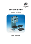
Heat Sealer
®
User Manual
Waters® Heat Sealer
Contents Page
Introduction ....................................................................................................3
Safety ...........................................................................................................3
Declaration of Conformity ................................................................................4
Caution and Safety Signs in Accordance with IEC 417 .......................................5
Technical Specifications ...................................................................................6
Environmental Requirements..............................................................................6
Installation and Set-up......................................................................................7
Operation Procedure (Sealing & Removing Seal) .................................................9
Cleaning Your Thermo-Sealer..........................................................................10
Guarantee...................................................................................................10
Contact Information.......................................................................................10
Technical Information
Circuit Diagram for 110v unit.........................................................................11
Circuit Diagram for 240v unit.........................................................................12
Fault Finding ................................................................................................13
Accessories .................................................................................................13
CAUTION: Avoid contact with the heater plate,
which can cause serious injury.
2
Introduction
The Waters® Heat Sealer offers a convenient method for heat
sealing collection plates made from various types of plastic.
The heat sealer provides heat to form a seal between the seal
and plate, preventing evaporative loss during exposure to the
atmosphere or for long-term storage.
Safety
The Waters® Heat Sealer must only be used in accordance with proper safety standards and
procedures, together with the instructions contained in this manual.
The unit has been designed and manufactured to conform to international safety specifications.
Under normal conditions, once the aluminum block is up to temperature, the amber heater lamp will
flicker on and off to maintain temperature. In the unlikely event of an over-temperature problem with
the heat sealer, the unit is fitted with a thermal cut out which removes power to the heater should the
block temperature exceed 220°C. If this is triggered the amber heater lamp will go out and will not
come back on. The block will gradually cool to room temperature. The thermal cut out cannot be
reset (for safety reasons) and the unit should be returned for repair.
If there is any doubt relating to the proper use of this equipment, refer to this manual or call your
Waters® representative. Only properly trained personnel should service this equipment.
3
Declaration of Conformity
The Waters® Heat Sealer, Model Numbers SP-0669/110 & SP-0669/220 have been designed
in accordance with, and satisfies the requirements of, article 11 of the Low Voltage Directive
73/23/EEC as realigned by 93/68/EEC on the harmonization of the laws of the Member States
relating to electrical equipment designed for use within certain voltage limits, to the essential requirements of BS EN 61010-1: 1993 & BS EN 61010-2-010:1995.
The Waters® Heat Sealer, Model Numbers SP-0669/110 & SP-0669/220 have been type tested
by EMC Projects NAMAS approved test house, and issued a certificate of testing No 3418/98 to
the following E.M.C. Standards:
EN 50081-1:
1992
EN 55022(B):
1994
EN 50082-1:
1997
EN 61000-4-3:
1997
EN 61000-4-2:
1995
EN 61000-4-4:
1995
EN 61000-4-5:
1995
EN 61000-4-6:
1996
EN 61000-4-11:
1994
Covering: Conducted Emissions, Radiated Emissions, Electrostatic Discharge, Radiated Immunity,
Surge, Fast Transient Bursts and Voltage Dips satisfying the EMC Directive(s) 89/336/EEC and
92/31/EEC as realigned by 93/68/EEC.
4
Caution and Safety Signs in Accordance with IEC 417
Caution
Refer to manual
Caution
Risk of electrical shock
Warning
Hot surface (this instrument is
fitted with an internal heater
with a maximum temperature of
220°C when switched on)
Only refit correct
type of fuse
Must be IEC 127 approved for
use in EU countries.
Must be CSA or UL listed or
recognized for use in USA
& Canada.
Mains Switch Symbols
I = ON
0 = OFF
5
Technical Specifications
Input Voltage
230 (nominal) Volts
110 (nominal) Volts
Input Frequency
47Hz – 63Hz
Power Consumption
110V Version 500 Watts
240V Version 400 Watts
Fuse Rating
5 Amp(T)
110 Volts
3.15 Amp(T) 240 Volts
Internal Heater
350 Watts (Ambient to 220°C max)
Instrument Housing
Sheet Metal
Dimensions
140 x 330 x 150mm
Instrument Weight
3.4kg
Environmental Requirements
Temperature Range
- Operating 10 to 35°C
- Storage -20 to 40°C
Relative Humidity
- Operating 10% to 80% non-condensing
- Storage 10% to 80% non-condensing
6
Installation and Set-up
WARNING – Do not operate this instrument in an atmosphere
containing explosive gases.
WARNING – Only approved power cord set must be used
with this instrument.
WARNING – If it is required to use an extension lead, the
lead must be earthed.
7
Before attempting to connect the unit to the electricity supply, or to operate the unit, please read the
operating information and pay particular attention to the following:
1.
Check the voltage marked on the unit’s rating plate against that of the mains supply. The unit is
supplied with a pre-wired plug and socket.
The fused plug supplied with the mains cable for use in the UK is fitted with the following value
fuse to protect the cable.
Supply
Fuse Fitted in Plug
Fuse Fitted in Sealer
240/220V
5 Amp
3.15 Amp
120/110V
No Fuse
5 Amp
The fuses in the unit protect the unit and the operator. Note: The second fuseholder fitted to the
rear of the sealer is a spare in the case of 110V units, but both fuseholders are operational in
the 240V units. Note that units marked 240V on the rating plate work at 220V; units marked
120V on the rating plate work at 110V. In both these cases, however, the heating rate will
degrade by approximately 16%.
Amber Light
Green Power Light
Power Switch
2.
Connect the unit to the mains electricity supply and switch on the power switch on the side of
the unit. If electricity is being supplied to the unit, the green power light will illuminate. If the
heater within the unit is receiving power then the amber light will also illuminate.
3.
When switching on, it is necessary to leave the unit on for 20–25 minutes to allow the unit to
come to the proper temperature before carrying out the first sealing operation.
On initial power-up, both green and amber lights will illuminate. After approximately 10–15
minutes the amber light will go out. DO NOT USE the Thermo-Sealer until 20-25 minutes has
elapsed from power-up. By this time the amber light will blink on and off constantly. The amber
light, blinking on and off, indicates the unit is at the correct working condition.
4.
The heater plate is set to approximately 170°C. Take care to avoid skin contact with the heater
plate and to prevent contact between the heater plate and any material which may be
damaged or ignited.
5.
In the event of spillage or other contamination of the unit, switch off and disconnect the unit from
the mains power supply, and do not attempt to clean the unit until it has thoroughly cooled.
If the equipment is used in a manner NOT specified by the manufacturer, the protection provided by the equipment may be impaired.
8
Operation Procedure
Sealing
After installation, follow the procedures set out below:
Check that the unit is connected to an appropriate power supply and leave for 20–25 minutes to
settle down to correct operating temperature. The green power lamp should be illuminated and the
amber heater lamp flicker on and off.
Slide the plate to be sealed onto the platform of the sealer, making sure that it is flat between the two
centralizing springs. You may also choose to slide the plate holder (black anodized metal plate)
between the springs.
Place the sealing film over the plate, ensuring that the sealing surface is face down.
Place one hand above the other on the handle on the top of the unit and push the heater head down
onto the seal and plate. Once the heater head touches, continue to push down to compress the
springs that are behind the heated plate. Once these are fully compressed (a distance of 5mm) the
force applied to the plate is 10kg. Each plate should be sealed in both orientations to achieve uniform sealing across the plate. Hold the heater head down for 3 seconds. Allow the heater head to
return to the top of the track.
Rotate the plate (180 degrees –
turn it end for end) in the unit and
seal again for 3 seconds.
Allow the heater head to return to the top of the track.
Remove the plate.
NOTE: Foil backed film may remain hot for a number of seconds after sealing. Care should be taken
in handling these plates.
Removing Seal
Depending on the seal type, samples can be accessed by either piercing the seal or peeling it off.
Seals
After piercing the seal, if storage and reuse are desired, peal off the seal and apply a new
seal for best storage results.
9
Cleaning Your Thermo-Sealer
Before using any cleaning or decontamination method other than that
recommended by the manufacturer, users should check with the manufacturer
that the proposed method will not damage the equipment.
Do not use acetone or abrasive cleaners.
The Thermo-Sealer cover can be cleaned with a cloth dipped in water or
ethanol (methanol or formaldehyde can also be used). The unit should not
be immersed in solvents.
Guarantee
This instrument is guaranteed against any defect in material or workmanship for a period as specified
on the enclosed guarantee. This period is from the date of purchase, and within this period all defective parts will be replaced free of charge provided that the defect is not the result of misuse, accident
or negligence. Servicing under this guarantee should be obtained from the supplier.
This User’s Manual has been prepared solely for the convenience of customers and nothing in this
User’s Manual shall be taken as a warranty, condition or representation concerning the description,
the merchantability, fitness for purpose or otherwise of the units or their components.
Contact Information
For technical, sales or servicing information, contact Waters Corporation.
IMPORTANT NOTE:
THIS EQUIPMENT SHOULD ONLY BE DISMANTLED BY PROPERLY TRAINED PERSONNEL.
REMOVING THE TOP CASE EXPOSES POTENTIALLY LETHAL MAINS VOLTAGES.
THERE ARE NO USER MAINTENANCE PARTS WITHIN THE EQUIPMENT.
10
Circuit Diagram for 110V Unit
11
Circuit Diagram for 240V Unit
12
Fault Finding
General
In the unlikely event that you experience any problems with your Heat Sealer which cannot be
easily remedied, you should contact Waters Corporation and return the unit in its original packing.
Accessories
For Waters selection of collection plates and seals, visit us at www.waters.com
720001330EN
©2005 Waters Corporation.
Waters is a registered trademark of Waters Corporation.
13