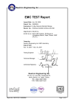
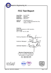
1
Compliance Certification Services Inc.
Report No.: T100830368-C
Date of Issue: Aug 30, 2010
C-Tick EMC
TEST REPORT
For
46” LCD Monitor
Model: PID-426WD
Trade Name: TYT, Non Brand
Issued for
Tiun Yuan Technology Co., Ltd.
6F, No.37, Lane 221, Gang Qian Road, Nei-Hu,
Taipei 114, Taiwan, R.O.C.
Issued by
Compliance Certification Service Inc.
No. 81-1, Lane 210, Pa-De 2nd Rd., Luchu Hsiang,
Taoyuan Shien, (338)Taiwan, R.O.C.
TEL:886-3-3245966
FAX:886-3-3245235
Note: This report shall not be reproduced except in full, without the written approval of Compliance
Certification Services Inc. Ltd. This document may be altered or revised by Compliance Certification Services
Inc. personnel only, and shall be noted in the revision section of the document.
Page 1
Total Page: 21
Rev.00
Compliance Certification Services Inc.
Report No.: T100830368-C
Date of Issue: Aug 30, 2010
TABLE OF CONTENTS
1
TEST RESULT CERTIFICATION……………….……………………….………..…..............3
2
EUT DESCRIPTION………………………….………………………………………………..4
3
TEST METHODOLGY……………….…………….………………………..……...................5
3.1 EUT SYSTEMOPERATION…………………………....……………………………..…..5
3.2 DECISION OF FINAL TEST MODE………..………………………………………….....6
4 SETUP OF EQUIPMENT UNDER TEST…………….……………………………………….7
5
FACILITES AND ACCREDITATIONS…………….…….…………………..……………..…8
5.1 FACILITES………...…………………….………………………………………..…..……8
5.2 LABORATORY ACCREDITIONS AND LISTING……………….…..……………..…….9
6 INSTRUMENT AND CALIBRATION…………………………………………………………10
6.1 MEASURING INSTRUMENT CALIBRATION……….……………………………….…10
6.2 TEST AND MEASUREMENT EQUIPMENT…………….………………………………10
7 LINE CONDUCTION & RADIATION EMISSION TEST……………………...……….…..11
7.1 LIMIT……………..………………..……………………………………..………………11
7.2 TEST PROCEDURE OF LINE CONDUCTION EMISSION…….………………...........12
7.3 TEST PROCEDURE OF RADIATION EMISSION……………………..………………14
7.4 TEST ESULTS……………………………………………………………………..………16
APPENDIX I PHOTOGRAPHS OF TEST SETUP…………………………………………….21
Page 2
Rev.00
Compliance Certification Services Inc.
Report No.: T100830368-C
1
Date of Issue: Aug 30, 2010
TEST RESULT CERTIFICATION
Applicant:
Tiun Yuan Technology Co., Ltd.
Manufacturer:
Tiun Yuan Technology Co., Ltd.
6F, No.37, Lane 221, Gang Qian Road, Nei-Hu,
Taipei 114, Taiwan, R.O.C.
Equipment Under Test:
6F, No.37, Lane 221, Gang Qian Road, Nei-Hu,
Taipei 114, Taiwan, R.O.C.
46” LCD Monitor
Trade Name:
TYT, Non brand
Model:
PID-426WD
Detail EUT Description:
See Item 2 of this report
Date of Test:
Aug 23~27, 2010
Applicable Standard
Class/Limit
Test Result
AS/NZS CISPR 22: 2006
Class A/ Required Limit
No non-compliance noted
Deviation from Applicable Standard
None
The above equipment was tested by Compliance Certification Services Inc. and found compliance
with the requirements set forth in the technical standards mentioned above. The test results of
testing in this report apply only to the product/system, which was tested. Other similar equipment
will not necessarily produce the same results due to production tolerance and measurement
uncertainties.
Approved by:
Reviewed by:
David Wang
Director of Linko Laboratory
Compliance Certification Services Inc.
Ethan Huang
Section of Linko Laboratory
Compliance Certification Services Inc.
Page 3
Rev.00
Compliance Certification Services Inc.
Report No.: T100830368-C
Date of Issue: Aug 30, 2010
2 EUT DESCRIPTION
Product
46” LCD Monitor
Trade Name
Model
TYT, Non Brand
PID-426WD
Housing Type
Metal
EUT Power Rating
110-240Vac, 50/60Hz, 5A
Power Supply Manufacturer
STARMEN
Model
TOM371CABB
LCD Panel Manufacturer
SAMSUNG
Model
LTI460AA03
AC Power Cord Type
Non-shield, 1.8m
I/O PORT OF EUT
I/O PORT TYPE
Q’TY
TESTED WITH
1). Video In Port(VGA)
1
1
2). DVI Port
1
1
3). HDMI Port
1
1
4). Audio In Port
1
1
5). Speaker Out Port(L/R)
1
1
6.) RS-323 port
1
0
Note: According to customer declaration, the RS-323 and Service Port of EUT is for control mode
and update firmware function only, so didn’t connect any support equipment.
Page 4
Rev.00
Compliance Certification Services Inc.
Report No.: T100830368-C
Date of Issue: Aug 30, 2010
3 TEST METHODOLOGY
3.1 EUT SYSTEM OPERATION
ITE EMISSION TEST:
1. EMI test program was loaded and executed in Windows XP mode.
2. Data was sent to EUT filling the screen with upper case of “H” patterns.
3. PC played music from CD-ROM and sent signal to EUT via an audio cable.
4. Test program sequentially exercised printer, then sent “H” patterns to them
individually.
5. Repeat the steps of 2 to 3.
Note:Test program is self-repeating throughout the test.
Page 5
Rev.00
Compliance Certification Services Inc.
Report No.: T100830368-C
Date of Issue: Aug 30, 2010
3.2 DECISION OF FINAL TEST MODE
1. The following test mode was scanned during the preliminary test:
Mode 1:1360 x 768 Resolution, 60Hz
Mode 2:1024 x 768 Resolution, 75Hz
Mode 3:800 x 600 Resolution, 75Hz
Mode 4:DVI
Mode 5:HDMI
2. After the preliminary scan, the following test mode was found to produce the
highest emission level.
Mode 1
Then, the EUT configuration and cable configuration of the above highest emission
mode was chosen for all final test items.
Page 6
Rev.00
Compliance Certification Services Inc.
Report No.: T100830368-C
Date of Issue: Aug 30, 2010
4 SETUP OF EQUIPMENT UNDER TEST
Setup Diagram
See test photographs attached in Appendix 1 for the actual connections
between EUT and support equipment.
Support Equipment
No
Equipment
Model
Serial No.
FCC ID
Trade Name
Data Cable
Power Cord
VGA Cable:
Shielded,1.8m
with two cores
Audio Cable:
Unshielded, 1.8m
Unshielded, 1.8m
1
PC
DX-6120
SGH5330GK7
FCC DoC
HP
2
Modem
DM-1414
304012266
IFAXDM1414
ACEEX
Shielded, 1.2m
Unshielded, 1.8m
3
Printer
STYLUS C60
DR3K043129
FCC DoC
EPSON
Shielded, 1.5m
Unshielded, 1.8m
4
PS/2 Keyboard
Y-SJ17
SY520U00642
FCC DoC
Logitech
Unshielded, 1.2m
N/A
5
PS/2 Mouse
M-SBF69
HCA45009243
FCC DoC
Logitech
Unshielded, 1.2m
N/A
6
Speaker
S-MS500CR
N/A
N/A
PIONEER
Unshield, 1.8m
N/A
Note: All the above equipment/cable was placed in worse case positions to maximize emission signals during
emission test.
Grounding: Grounding was in accordance with the manufacturer’s requirements and conditions for the
intended use.
Page 7
Rev.00
Compliance Certification Services Inc.
Report No.: T100830368-C
Date of Issue: Aug 30, 2010
5 FACILITIES AND ACREDITATIONS
FACILITIES
All measurement facilities used to collect the measurement data are located at CCS
Taiwan Linkou Lab at No. 81-1, Lane 210, Bade Rd.,2, Luchu Hsiang, Taoyuan Hsien,
Taiwan.
The measurement facilities are constructed in conformance with the requirements fo
CISPR 16-1, ANSI C63.4 and other equivalent standards.
Page 8
Rev.00
Compliance Certification Services Inc.
Report No.: T100830368-C
Date of Issue: Aug 30, 2010
LABORATORY ACCREDITATIONS AND LISTINGS
The test facilities used to perform Electromagnetic compatibility tests are registered or accredited by
the organizations listed in the following table which includes the recognized scope specifically.This
accredited organization maintains A2LA accreditation to ISO/IEC 17025 for the specific test listed in
A2LA Certificate # 0824-01.
Country Agency Scope of Accreditation
Logo
USA
A2LA
EN 55011, EN 55014-1/2, CISPR 11, CISPR
14-1/2, EN 55022, EN 55015, CISPR 22, CISPR
15, AS/NZS 3548, VCCI V3 (2001), CFR 47,
FCC Part 15/18, CNS 13783-1, CNS 13439, CNS
13438, CNS 13803, CNS 14115, EN 55024, IEC
801-2, IEC 801-3, IEC 801-4, IEC/EN 61000-3-2,
EIC/EN 61000-3-3,
IEC/EN 61000-4-2/3/4/5/6/8/11, EN 50081-1/EN
61000-6-3, EN 50081-2/EN 61000-6-4, EN
50081-2/EN 61000-6-1: 2001
USA
FCC
3/10 meter Open Area Test Sites to perform FCC
Part 15/18 measurements
3/10 meter Open Area Test Sites and conducted
test sites to perform radiated/conducted
measurements
93105, 90471
Japan
VCCI
Norway
EN 50081-1/2, EN 50082-1/2, IEC 61000-6-1/2,
EN 50091-2, EN 50130-4, EN 55011, EN 55013,
EN 55014-1/2, EN 55015, EN 55022, EN 55024,
EN 61000-3-2/3, EN 61326-1,
NEMKO
IEC 61000-4-2/3/4/5/6/8/11, EN 60601-1-2,
ELA 124a
EN 300 328-2, EN 300 422-2, EN 301 419-1,
ELA 124b
EN 301 489-01/03/07/08/09/17, EN 301 419-2/3, ELA 124c
EN 300 454-2, EN 301 357-2
Taiwan
TAF
R-393/2316/725/1868
C-402/747/912
EN 300 328-1, EN 300 328-2, EN 300 220-1,
EN 300 220-2, EN 300 220-3, 47 CFR FCC Part
15 Subpart C, EN 61000-3-2, EN 61000-3-3,
CNS 13439, CNS 13783-1, CNS 14115,
CNS 13438, AS/NZS CISPR 22, CNS 13022-1,
IEC 61000-4-2/3/4/5/6/8/11, CNS 13022-2/3
Taiwan
BSMI
CNS 13438, CNS 13783-1, CNS 13439,
CNS 14115
Canada
Industry
Canada
RSS212, Issue 1
SL2-IS-E-0014 / IN-E-0014
/A1-E-0014 /R1-E-0014
/R2-E-0014 /L1-E-0014
IC 3991-3
IC 3991-4
Note: No part of this report may be used to claim or imply product endorsement by A2LA, TAF or other
government agency.
Page 9
Rev.00
Compliance Certification Services Inc.
Report No.: T100830368-C
Date of Issue: Aug 30, 2010
6 INSTRUMENT AND CALIBRATION
6.1 MEASURING INSTRUMENT CALIBRATION
The measuring equipment utilized to perform the tests documented in this report has
been calibrated once a year or in accordance with the manufacturer’s recommendations,
and is traceable under the IEC 17025 to international or national standards. Equipment
has been calibrated by accredited calibration laboratories.
6.2 TEST AND MEASUREMENT EQUIPMENT
The following list contains measurement equipment used for testing. The equipment
conforms to the requirement of CISPR 16-1-1, CISPR 16-1-2, CISPR 16-1-3, CISPR
16-1-4, CISPR 16-1-5, ANSI C63.2 and other required standards.
Calibration of all test and measurement, including any accessories that may effect such
calibration, is checked frequently to ensure the accuracy. Adjustments are made and
correction factors are applied in accordance with the instructions contained in the
respective manual.
Equipment Used for Emission Measurement
Conducted Emission Test Site # 4
Name of Equipment
Manufacturer
Model
Serial Number
Calibration Due.
EMI Test Receiver
R&S
ESCS30
847793/012
02/26/2011
LISN
R&S
ENV216
100066
05/09/2011
LISN
R&S
ENV 4200
830326/016
04/09/2011
Note: The measurement uncertainty is less than +/- 1.7983dB, which is evaluated as per the NAMAS NIS 81 and
CISPR/A/291/CDV.
Open Area Test Site # 1
Name of Equipment
Manufacturer
Model
Serial Number
Calibration Due.
Spectrum Analyzer
ADVANTEST
R3261C
81720301
N.C.R
EMI Test Receiver
R&S
ESVS20
838804/004
01/18/2011
Pre-Amplifier
HP
8447D
2944A09173
03/22/2011
Bilog Antenna
Sunol Sciences
JB1
A111203
03/24/2011
Turn Table
EMCO
2081-1.21
N/A
N.C.R
Antenna Tower
EMCO
2075-2
9707-2604
N.C.R
Controller
EMCO
2090
N/A
N.C.R
RF Switch
Anritsu
MP59B
M54367
N.C.R
Site NSA
CCS
N/A
N/A
11/18/2010
Note: The measurement uncertainly is less than +/- 3.36dB, which is evaluated as per the NAMAS NIS 81 and
CISPR/A/291/CDV.
Page 10
Rev.00
Compliance Certification Services Inc.
Report No.: T100830368-C
Date of Issue: Aug 30, 2010
7 LINE CONDUCTED & RADIATED EMISSION TEST
7.1 LIMIT
Maximum permissible level of Line Conducted Emission
Class A(dBuV)
Class B (dBuV)
Frequency
(MHZ)
Quasi-peak
Average
Quasi-peak
Average
0.15 – 0.5
79
66
66 -56
56 - 46
0.50 – 5.0
73
60
56
46
5.0 – 30.0
73
60
60
50
Note:The lower limit shall apply at the transition frequency.
Maximum permissible level of Radiated Emission measured at 10 meter
Frequency
(MHZ)
Class A(dBuV/m)
Class B (dBuV/m)
Quasi-peak
Quasi-peak
30 - 230
40
30
230 - 1000
47
37
Note:The lower limit shall apply at the transition frequency.
Maximum permissible level of Radiated Emission measured at 3 meter
Class A(dBuV/m)
Class B (dBuV/m)
Frequency
(MHZ)
Average
peak
Average
peak
Above 960
59.5
79.5
54
74
Note:The lower limit shall apply at the transition frequency.
Page 11
Rev.00
Compliance Certification Services Inc.
Report No.: T100830368-C
7.2
Date of Issue: Aug 30, 2010
TEST PROCEDURE OF LINE CONDUCTED EMISSION
Procedure of Preliminary Test
z The EUT was set up as per the test configuration to simulate typical actual usage per the user’s
manual. When the EUT is a tabletop system, a wooden table with a height of 0.8 meters is used
and is placed on the ground plane as per AS/NZS CISPR 22 (see Test Facility for the dimensions
of the ground plane used). When the EUT is a floor standing equipment, it is placed on the ground
plane which has a 3-12 mm non-conductive covering to insulate the EUT from the ground plane.
z Support equipment, if needed, was placed as per AS/NZS CISPR 22.
z All I/O cables were positioned to simulate typical actual usage as per AS/NZS CISPR 22.
z The test equipment EUT installed received AC power, 240VAC/50Hz, through a Line Impedance
Stabilization Network (LISN), which supplied power source and was grounded to the ground
plane.
z All support equipment received power from a second LISN.
z The EUT test program was started. Emissions were measured on each current carrying line of the
EUT using a EMI Test Receiver connected to the LISN powering the EUT. The LISN has two
monitoring points: Line 1 (Hot Side) and Line 2 (Neutral Side). Two scans were taken: one with
Line 1 connected to Receiver and Line 2 connected to a 50 ohm load; the second scan had Line 1
connected to a 50 ohm load and Line 2 connected to the Receiver.
z The Receiver scanned from 150kHz to 30MHz for emissions in each of the test modes.
z During the above scans, the emissions were maximized by cable manipulation.
z The test mode(s) described in Item 3.2 were scanned during the preliminary test.
z After the preliminary scan, we found the following the test mode described in Item 3.2 producing
the highest emission level.
z The EUT configuration and cable configuration of the above highest emission level were recorded
for reference of final testing.
Page 12
Rev.00
Compliance Certification Services Inc.
Report No.: T100830368-C
Date of Issue: Aug 30, 2010
Procedure of Final Test
z EUT and support equipment was set up on the test bench as per step 10 of the preliminary test.
z A scan was taken on both power lines, Line 1 and Line 2, recording at least the six highest
emissions. Emission frequency and amplitude were recorded into a computer in which
correction factors were used to calculate the emission level and compare reading to the applicable
limit. If EUT emission level was less -2dB to the AV. Limit in Q.P. mode, then the emission signal
was re-checked using an AV. Detector.
z The test data of the worst case condition(s) was recorded.
Test Setup:
z For the actual test configuration, please refer to the related item-Photographs of the Test
configuration.
Data Sample:
Freq.
MHz
x.xx
Q.P. Average Corr.
Raw
Raw
Factor
(dBuV) (dBuV) (dB)
43.95
33
10
Q.P. Average Q.P. Average Q.P. Average
Result Result Limit
Limit Margin Margin Remark
(dBuV) (dBuV) (dBuV) (dBuV) (dB)
(dB)
53.95
43
56
46
-2.05
-3
Freq.
Raw dBuV
Corr. Factor dB
Result dBuV
Limit dBuV
Margin dB
= Emission frequency in MHz
= Uncorrected Analyzer / Receiver reading
= Antenna factor+ Cable loss- Amplifier gain
= Raw reading converted to dBuV and CF added
= Limit stated in standard
= RAW(dBuV) – Limit(dBuV)
Q.P.
= Quasi-Peak
Page 13
L1
Rev.00
Compliance Certification Services Inc.
Report No.: T100830368-C
Date of Issue: Aug 30, 2010
7.3 TEST PROCEDURE OF RADIATED EMISSION
Procedure of Preliminary Test
z The equipment was set up as per the test configuration to simulate typical actual usage per the
user’s manual. When the EUT is a tabletop system, a wooden turntable with a height of 0.1
meters is used which is placed on the ground plane. When the EUT is a floor-standing equipment,
it is placed on the ground plane which has a 3-12 mm non-conductive covering to insulate the
EUT from the ground plane.
z Support equipment, if needed, was placed as per AS/NZS CISPR 22.
z All I/O cables were positioned to simulate typical actual usage as per AS/NZS CISPR 22.
z The EUT received AC power source, 240VAC/50Hz, from the outlet socket under the turntable.
All support equipment received power from another socket under the turntable.
z The antenna was placed at 10 meter away from the EUT as stated in AS/NZS CISPR 22. The
antenna connected to the Spectrum Analyzer via a cable and at times a pre-amplifier would be
used.
z The Analyzer / Receiver quickly scanned from 30MHz to 40GHz maximum, if any. The EUT test
program was started. Emissions were scanned and measured rotating the EUT to 360 degrees and
positioning the antenna 1 to 4 meters above the ground plane, in both the vertical and the
horizontal polarization, to maximize the emission reading level.
z The test mode(s) described in Item 3.2 were scanned during the preliminary test.
z After the preliminary scan, we found the following the test mode described in Item 3.2 producing
the highest emission level.
z Then, the EUT and cable configuration, antenna position, polarization and turntable position of
the above highest emission level were recorded for the final test.
Page 14
Rev.00
Compliance Certification Services Inc.
Report No.: T100830368-C
Date of Issue: Aug 30, 2010
Procedure of Final Test
z EUT and support equipment were set up on the turntable as per step 8 of the preliminary test.
z The Analyzer / Receiver scanned from 30MHz to 40GHz maximum, if any. Emissions were
scanned and measured rotating the EUT to 360 degrees, varying cable placement and positioning
the antenna 1 to 4 meters above the ground plane, in both the vertical and the horizontal
polarization, to maximize the emission reading level.
z Recorded at least the six highest emissions. Emission frequency, amplitude, antenna position,
polarization and turntable position were recorded into a computer in which correction factors were
used to calculate the emission level and compare reading to the applicable limit and only Q.P.
reading is presented.
z The test data of the worst case condition(s) was recorded.
Test Setup:
z For the actual test configuration, please refer to the related item-Photographs of the Test
configuration.
Data Sample:
Freq.
MHz
Reading
(dBuV)
Corr.
Factor
(dB/m)
x.xx
16.49
9.86
Freq.
Reading(dBuV)
Corr. Factor(dB/m)
Result (dBuV/m)
Limit (dBuV/m)
Margin dB
Q.P.
Result
Limit
Margin
(dBuV/m) (dBuV/m)
(dB)
26.35
30.00
-3.65
Degree
(∘)
Heigh
(cm)
Remark
116.00
101.00
QP
= Emission frequency in MHz
= Uncorrected Analyzer / Receiver reading
= Antenna factor+ Cable loss- Amplifier gain
= Reading(dBuV) + Corr. Factor(dB/m)
= Limit stated in standard
= Result(dBuV/m) – Limit(dBuV/m)
= Quasi-Peak
Page 15
Rev.00
Compliance Certification Services Inc.
Report No.: T100830368-C
Date of Issue: Aug 30, 2010
7.4 TEST RESULTS
Line Conduction Emission
Linkou Conduction 4
Job No.:
Standard:
Test Item:
Temp.(°C)/Hum.(%RH):
Company:
Model:
NO. Frequency
(MHz)
1
2
3
4
5
6
0.2571
0.3831
0.6388
0.9044
1.1444
1.4006
T100830368
CISPR 22 Class A
Conduction Emission
25°C/53%RH
TYT
PID-426WD
Line:
L1
Date:
Time:
Tested By:
Test Mode:
2010/08/24
AM 11:05
Eason
Mode 1
Quasi Average Correction Quasi Average Quasi Average Quasi Average Remark
Peak reading
factor
Peak
result
Peak
limit
Peak
margin
reading
result
limit
margin
(dBuV) (dBuV)
(dB)
(dBuV) (dBuV) (dBuV) (dBuV)
(dB)
(dB)
(Pass/Fail)
42.70
47.79
44.93
42.40
41.95
41.18
31.82
43.56
37.87
31.21
30.73
28.69
9.65
9.65
9.55
9.56
9.57
9.60
52.35
57.44
54.48
51.96
51.52
50.78
41.47
53.21
47.42
40.77
40.30
38.29
79.00
79.00
73.00
73.00
73.00
73.00
66.00
66.00
60.00
60.00
60.00
60.00
-26.65
-21.56
-18.52
-21.04
-21.48
-22.22
-24.53
-12.79
-12.58
-19.23
-19.70
-21.71
Pass
Pass
Pass
Pass
Pass
Pass
L1=Line One(Live Line)
Page 16
Rev.00
Compliance Certification Services Inc.
Report No.: T100830368-C
Date of Issue: Aug 30, 2010
Linkou Conduction 4
Job No.:
Standard:
Test Item:
Temp.(°C)/Hum.(%RH):
Company:
Model:
Frequency
(MHz)
Quasi
Peak
reading
(dBuV)
0.2541
0.3813
0.6374
0.9123
1.1423
1.4063
40.79
48.05
45.35
42.42
42.08
41.29
NO.
1
2
3
4
5
6
T100830368
CISPR 22 Class A
Conduction Emission
25°C/53%RH
TYT
PID-426WD
Line:
L2
Date:
Time:
Tested By:
Test Mode:
2010/08/24
AM 11:46
Eason
Mode 1
Average Correction Quasi Average Quasi
reading
factor
Peak
result
Peak
result
limit
(dBuV)
(dB)
(dBuV) (dBuV) (dBuV)
31.60
44.41
38.54
30.30
31.42
27.92
9.66
9.66
9.56
9.57
9.58
9.61
50.45
57.71
54.91
51.99
51.66
50.90
41.26
54.07
48.10
39.87
41.00
37.53
79.00
79.00
73.00
73.00
73.00
73.00
Average
limit
(dBuV)
66.00
66.00
60.00
60.00
60.00
60.00
Quasi Average Remark
Peak
margin
margin
(dB)
(dB) (Pass/Fail)
-28.55
-21.29
-18.09
-21.01
-21.34
-22.10
-24.74
-11.93
-11.90
-20.13
-19.00
-22.47
Pass
Pass
Pass
Pass
Pass
Pass
L2=Line Two(Neutral Line)
Page 17
Rev.00
Compliance Certification Services Inc.
Report No.: T100830368-C
Date of Issue: Aug 30, 2010
Radiation Emission(A)
CCS Radiated Test OATS 1
Job No.:
Standard:
Test Item:
Temp.(°C)/Hum.(%RH):
Company:
Model:
No.
1
2
3
4
5
6
7
8
9
10
11
Frequency
(MHz)
65.00
78.16
108.18
163.14
194.95
246.10
378.60
458.60
644.70
758.00
811.20
Reading
(dBuV)
46.08
52.50
43.86
39.56
43.75
37.65
30.70
30.94
26.50
25.48
26.69
T100702109
CISPR 22 Class A
Radiated Emission
33°C/63%RH
TYT
PID-426WD
Ant. Polar.:
Tested Distance:
Date:
Time:
Tested By:
Test Mode:
Correction
Result
Limit
Factor(dB/m) (dBuV/m) (dBuV/m)
-18.38
27.70
40.00
-16.73
35.77
40.00
-12.06
31.80
40.00
-13.56
26.00
40.00
-13.13
30.62
40.00
-9.25
28.40
47.00
-5.30
25.40
47.00
-2.94
28.00
47.00
0.40
26.90
47.00
2.32
27.80
47.00
2.91
29.60
47.00
Page 18
Margin
(dB)
-12.30
-4.23
-8.20
-14.00
-9.38
-18.60
-21.60
-19.00
-20.10
-19.20
-17.40
Ver.
10m
2010/8/25
PM 14:15
Tony Tsai
Mode 1
Degree
(°)
61.40
129.70
197.40
229.50
81.50
254.20
322.80
176.40
18.00
0.00
345.60
Height
(cm)
100.00
100.00
100.00
100.00
100.00
400.00
300.00
144.10
121.00
100.00
100.00
Remark
Peak
QP
Peak
Peak
Peak
Peak
Peak
Peak
Peak
Peak
Peak
Rev.00
Compliance Certification Services Inc.
Report No.: T100830368-C
Date of Issue: Aug 30, 2010
Radiation Emission(B)
CCS Radiated Test OATS 1
Job No.:
Standard:
Test Item:
Temp.(°C)/Hum.(%RH):
Company:
Model:
No.
1
2
3
4
5
6
7
8
9
10
Frequency
(MHz)
70.00
78.40
144.78
163.79
229.12
244.90
305.53
540.20
743.40
889.50
Reading
(dBuV)
41.49
42.09
33.37
39.77
46.90
39.01
44.09
31.57
28.97
28.15
T100702109
CISPR 22 Class A
Radiated Emission
33°C/63%RH
TYT
PID-426WD
Ant. Polar.:
Tested Distance:
Date:
Time:
Tested By:
Test Mode:
Correction
Result
Limit
Factor(dB/m) (dBuV/m) (dBuV/m)
-18.09
23.40
40.00
-16.69
25.40
40.00
-11.97
21.40
40.00
-13.57
26.20
40.00
-11.60
35.30
40.00
-9.41
29.60
47.00
-6.87
37.22
47.00
-1.57
30.00
47.00
2.03
31.00
47.00
3.45
31.60
47.00
Page 19
Margin
(dB)
-16.60
-14.60
-18.60
-13.80
-4.70
-17.40
-9.78
-17.00
-16.00
-15.40
Ver.
10m
2010/8/25
PM 16:18
Tony Tsai
Mode 1
Degree
(°)
253.30
197.10
259.10
15.40
296.10
251.80
0.00
0.00
0.00
360.00
Height
(cm)
400.00
400.00
400.00
400.00
400.00
400.00
303.30
134.90
100.00
100.00
Remark
Peak
Peak
Peak
Peak
Peak
Peak
Peak
Peak
Peak
Peak
Rev.00
Compliance Certification Services Inc.
Report No.: T100830368-C
Date of Issue: Aug 30, 2010
Radiated Emission-Above 1GHz(A)
Model: PID-426WD
Test Mode: Mode 1
Temperature: 33℃
Humidity: 56% RH
Detector Function: Pk/ A.V.
Antenna: Vertical at 3m
Test By: Tony Tsai
Test Results: Pass
(The chart below shows the highest readings taken from the final data)
Freq.
(MHz)
Reading
(dBuV)
1009.27
1112.23
1186.51
1489.77
1615.49
2495.39
59.75
57.00
54.00
57.75
58.25
54.25
Corr
Factor
(dB/m)
-12.71
-12.20
-11.84
-10.35
-9.64
-6.75
Emiss. Level
(Pk)
(dBuV/m)
47.04
44.80
42.16
47.40
48.61
47.50
Limit 3m
(Pk)
(dBuV/m)
79.50
79.50
79.50
79.50
79.50
79.50
Margin
(dB)
-32.46
-34.70
-37.34
-32.10
-30.89
-32.00
Note: In case of peak reading complied with the limit at least 22dB margin, no measurement with A.V. detector required.
Radiated Emission-Above 1GHz(B)
Model: PID-426WD
Test Mode: Mode 1
Temperature: 33℃
Humidity: 56% RH
Detector Function: Pk/ A.V.
Antenna: Horizontal at 3m
Test By: Tony Tsai
Test Results: Pass
(The chart below shows the highest readings taken from the final data)
Freq.
(MHz)
Reading
(dBuV)
1009.43
1086.71
1112.71
1186.43
1286.71
1312.57
57.00
56.75
57.00
56.50
58.25
54.25
Corr
Factor
(dB/m)
-12.71
-12.33
-12.20
-11.84
-11.34
-11.22
Emiss. Level
(Pk)
(dBuV/m)
49.29
49.42
49.80
49.66
51.91
48.03
Limit 3m
(Pk)
(dBuV/m)
79.50
79.50
79.50
79.50
79.50
79.50
Margin
(dB)
-30.21
-30.08
-29.70
-29.93
-27.59
-31.47
Note: In case of peak reading complied with the limit at least 22dB margin, no measurement with A.V. detector required.
Page 20
Rev.00
Compliance Certification Services Inc.
Report No.: T100830368-C
Date of Issue: Aug 30, 2010
APPENDIX I – PHOTOGRAPHS OF TEST SETUP
LINE CONDUCTED EMISSION TEST
Page 21
Rev.00
Compliance Certification Services Inc.
Report No.: T100830368-C
Date of Issue: Aug 30, 2010
RADIATED EMISSION TEST
Page 22
Rev.00