1
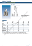
APS-M1
Accessories · Sensor System · Analog Position Sensor
Wiring diagram
VCC
SW
VCC
U+
OSC
V
U–
rt
ws
BR1
BR2
I+
bl
A
OSC
I–
GND
GND
APS-M1S Sensor
APS-M1E Electronic Processor
Automation device, e.g. S7-300
L When using an APS system, a mounting kit, APS
sensor (APS-M1S) and processor (APS-M1E) are
required for each gripper. The mounting kits can
be found with the grippers. Mounting kits for other
components/grippers are available on request.
The sensor has a 3 m molded cable.
Technical data
Description
Measuring stroke
Measuring accuracy
Nominal current input
Tightness
Thermal drift of zero signal
Thermal drift of amplification factor
Min. ambient temperature
Max. ambient temperature
Weight
Sensor material
Cable sheath
ID
[mm]
[mm]
[A]
[%/10K]
[%/10K]
[°C]
[°C]
[kg]
Description
ID
Supply voltage
Nominal voltage
Min. voltage
Max. voltage
Nominal current
IP rating
Min. ambient temperature
Max. ambient temperature
Repeat accuracy (sensor and processor)
Weight
Housing material
Output signal
Mounting
1016
[V]
[V]
[V]
[A]
[°C]
[°C]
[mm]
[kg]
APS-M1S
0302062
2.0
0.004
0.023
67
0.1
0.2
10.0
60.0
0.16
Steel
PUR
APS-M1E
0302064
DC
24.0
22.0
26.0
0.1
20
0.0
60.0
0.3
0.16
PA
0..10 V DC | 4..20 mA
top hat rail
www.schunk.com