1
6
RSTi-EP Slice I/O Digital Output Modules
GFK-2959
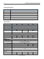
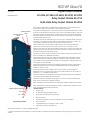
LED
EP-2714
Module
Status
Green: Communication over the system bus
Red: No communication on system bus or
diagnostic message displayed
1.1
EP-2814
Green: Communication over the system bus
Red: Collective error diagnostic
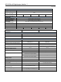
1.2
Yellow: Output 0 active
--
Yellow: Output 0 active
--
1.3
--
--
1.4
--
--
2.1
Yellow: Output 1 active
2.2
--
Yellow: Output 1 active
--
2.3
--
--
2.4
--
--
3.1
Yellow: Output 2 active
Yellow: Output 2 active
3.2
--
--
3.3
--
--
3.4
--
--
4.1
Yellow: Output 3 active
Yellow: Output 3 active
4.2
4.3
4.4
----
----
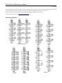
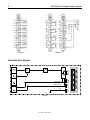
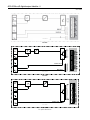
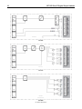
Field Wiring
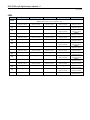
The connection frame can take up to four connectors, and four wires can be connected to each connector. The Spring
style technology allows for either finely stranded or solid wire with crimped wire-end ferrules or ultrasonically welded
wires, each with a maximum cross-section of 1.5 mm² (16 guage), to be inserted easily through the opening in the
clamping terminal without having to use tools. To insert fine stranded wires without wire-end ferrules, the pusher must
be pressed in with a screwdriver and released to latch the wire.
NC 0
COMM 0
COMM 0
COMM 0
NO 0
NO 0
NO 0
EP-2714
Connector with Four Wire Connectors
EP-2814
COMM 0 Connector Block (for Relay/SSR Modules)
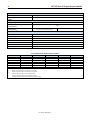
Connector Specifications:
• wire cross-section 0.14 to 1.5 mm² (26 – 16 guage)
• max. ampacity: 10 A
• 4-pole
The pushers are color-coded for the following connections:
• White Signal
• Blue
GND
• Red
24 V DC
• Green Functional earth (FE)
For public disclosure