1
StandAlone Aircraft: Selecting this option allows a player to insert an inflight aircraft into the
scenario that is not associated with an airport nor aircraft capable ship. An Add Aircraft dialog box
will appear allowing you to select the country, class, and name of the aircraft you want to insert,
see Object Properties Panel/Inflight Aircraft Properties, on p.36.
Environmental Object: Selecting this option allows you to insert a whale, school of shrimp, or an
iceberg into the scenario, see Object Properties Panel/Environmental Properties, on p.34.
Dynamic Location: This option let you specify a location where a selected mission object or group
of mission objects will be randomly placed at start mission. If you have entered three Dynamic
Locations and designate three objects for dynamic placement, each object will be randomly
assigned to one of the three locations when the mission loads. If more than three objects are
designated, multiple objects will be assigned to some dynamic locations. See Object Properties
Panel/Dynamic Location Properties, on p. 33.
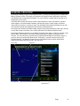
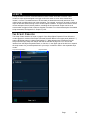
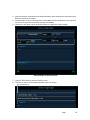
Select Dynamic location then click the map.
Click ADD in the Object Properties Panel. A list of al object currently added in the mission appears.
Select an object to add to a dynamic location.
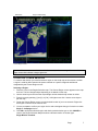
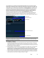
Chart Text Label: When this option is selected the Map Cursor changes to a + and you are
prompted in the Description Bar to click the map to place a label. A text label appears on the
clicked location as a small red square followed by the word Label and a sequentially higher number
with each label placed. By default the square and the text are red. The text and the color can be
changed.
1. Click the small square to bring up the Text Label properties panel on the right of the screen.
2. Set the text content in the Label edit box.
3. Select the desired color in the Text Color drop-down.
4. Click in the square to drag the label to a new location.
Note: Text labels placed here appear as map text when the scenario is played.
Chart Lines: When this option is selected the Map Cursor changes to a + and you are prompted in
the Description Bar to click the map to add lines.
1. Click the map to place a line’s starting point.
2. Click the desired point to draw the line to that location.
3. Click additional point to place a line to that point from the previous one.
4. Press [Esc] to complete the process.
5. To delete a line, click it to select it and press [Delete]. Each line must be deleted separately. A
selected line is yellow.
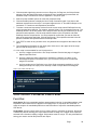
Chart Circle: When this option is selected the Map cursor changes to a +.
1. Click the map to place the center of the circle. A white circle appears with default radius of 10
nm, a white square at the center and the word circle in green and a sequentially higher number
with each circle placed. (You must be zoomed in to see the circle.)
2. Click on the white square to select it. The square turns red.
3. The Map Circle’s properties panel appears.
4. In the Circle Radius edit box enter the desired radius. Click the map to implement the change.
5. In the Circle Color drop-down select the desired color of the circle.
Page
25