1
Before performing service or maintenance operations on unit,
turn off gas supply then unit main power switch. Electrical
shock or explosion could cause serious injury or death.
A
C
MAXIMUM ALLOWABLE
DIFFERENCE (in.)
B
Puron (R-410A) systems operate at higher pressures than
standard R-22 systems. Do not use R-22 service equipment or
components on Puron (R-410A) equipment. Ensure service
equipment is rated for Puron (R-410A).
A-B
B-C
A-C
1/4
1/4
1/4
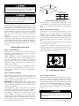
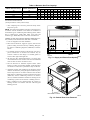
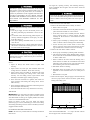
Fig. 2—Unit Leveling Tolerances
C99065
GROUND MOUNT — The unit may be installed either on a slab
or placed directly on the ground if local codes permit. Place the
unit on level ground prepared with gravel for condensate discharge.
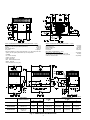
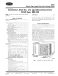
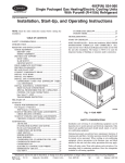
GENERAL — The 48GP units (see Fig. 1) are fully selfcontained, combination Category I gas heating/electric cooling
units designed for outdoor installation. See Fig. 6 and 7 for unit
dimensions. All unit sizes have discharge openings for both
horizontal and downflow configurations, and are factory shipped
with all downflow duct openings covered . Units may be installed
either on a rooftop, cement slab, or directly on the ground (if
permitted by local codes). See Figs. 4 and 5 for roof curb
dimensions.
48GPN units are dedicated Low NOx units designed for California
installations. These models meet the California maximum oxides
of nitrogen (NOx) emissions requirement of 40 nanograms/joule or
less as shipped from the factory and MUST be installed in
California Air Quality Management Districts where a Low NOx
rule exists.
Step 3—Field Fabricate Ductwork
Secure all ducts to roof curb and building structure on vertical
discharge units. Do not connect ductwork to unit. For horizontal
applications, unit is provided with flanges on the horizontal
openings. All ductwork should be secured to the flanges. Insulate
and weatherproof all external ductwork, joints, and roof openings
with counter flashing and mastic in accordance with applicable
codes.
Ducts passing through an unconditioned space must be insulated
and covered with a vapor barrier.
If a plenum return is used on a vertical unit, the return should be
ducted through the roof deck to comply with applicable fire codes.
RECEIVING AND INSTALLATION
A minimum clearance is not required around ductwork. Cabinet
return-air static shall not exceed -.25 in. wg.
Step 1—Check Equipment
6
IDENTIFY UNIT — The unit model number and serial number
are stamped on unit identification plate. Check this information
against shipping papers and job data.
OPTIONAL
RETURN
AIR
OPENING
INSPECT SHIPMENT — Inspect for shipping damage while unit
is still on shipping pallet. If unit appears to be damaged or is torn
loose from its anchorage, have it examined by transportation
inspectors before removal. Forward claim papers directly to
transportation company. Manufacturer is not responsible for any
damage incurred in transit.
OPTIONAL
SUPPLY
AIR
OPENING
2"
Check all items against shipping list. Immediately notify the
nearest Carrier Air Conditioning office if any item is missing.
EVAP. COIL
COND. COIL
C99014
To prevent loss or damage, leave all parts in original packages
until installation.
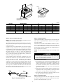
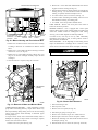
Fig. 3—Slab Mounting Details
Step 2—Provide Unit Support
ROOF CURB — Install accessory roof curb in accordance with
instructions shipped with curb. See Figs. 4 and 5 and Table 1 for
roof curb dimensions. Install insulation, cant strips, roofing, and
flashing. Ductwork must be attached to curb.
Step 4—Provide Clearances
The required minimum operating and service clearances are shown
in Fig. 6 and 7. Adequate combustion, ventilation, and condenser
air must be provided, in accordance with section 5.3, Air for
Combustion and Ventilation, of the National Fuel Gas Code ANSI
(American National Standards Institute) Z223.1 (in Canada, sections 7.2, 7.3 or 7.4 or Can/CGA [Canadian Gas Association]
B149 Installation Codes), or applicable provisions of local building code.
IMPORTANT: The gasketing of the unit to the roof curb is critical
for a watertight seal. Install gasketing material supplied with the
roof curb. Improperly applied gasketing can also result in air leaks
and poor unit performance.
Curb should be level to within 1 /4 inch. This is necessary for unit
drain to function properly. Refer to accessory roof curb installation
instructions for additional information as required (see Fig. 2).
SLAB MOUNT — Place the unit on a solid, level concrete pad
that is a minimum of 4 in. thick with 2 in. above grade. The slab
should be flush on the compressor end of the unit (to allow
condensate drain installation) and should extend 2 in. on the three
remaining sides of the unit. See Fig. 3. Do not secure the unit to the
slab except when required by local codes.
Do not restrict condenser airflow. An air restriction at either
the outdoor-air inlet or the fan discharge can be detrimental to
compressor life.
The condenser pulls air through the condenser coil and discharges
it through the top cover. Be sure that the fan discharge does not
2