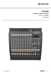
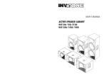
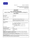
1
High Efficiency Power Amplifier X-DA4125 User Manual M_XXXXXX_EN_1.0 Copyright © 2011 Honeywell International Inc. All rights reserved. No part of this document may be reproduced in any form without the written permission of the copyright owner. Disclaimer The contents of this document are subject to revision without notice due to continued progress in methodology, design, and manufacturing. Honeywell shall have no liability for any error or damage of any kind resulting from the use of this document. Trademark List All trademarks mentioned herein are the property of their respective owners. These are shown in the document Trademark Information. Safety Guidelines Danger Warns users that they may encounter dangerous levels of voltage. Caution Provides important emphasis for the related product details. Safety Guidelines To prevent an electric shock, do not use an extension cord when connecting the appliance to a plug outlet. Do not block the appliance air vents by placing other equipment on top of it. Safety Guidelines Do not expose the appliance to rain or moisture to avoid causing a fire or an electric shock. Safety Precautions For the installation, operation, and use of this product, please carefully read the following precautions. Electrical Safety • The product installation and use must comply with local electrical safety regulations. • Honeywell assumes no liability for user errors or misuse that result in a fire or an electrical shock. Transportation Safety • During transportation, do not violently shake the appliance or expose it to corrosive liquids. i Environmental Regulations • Do not install the appliance in an environment with extreme temperatures or excessive amounts of dust. • The appliance should be placed away from direct sunlight in a well-ventilated, clean, and stable environment without vibrations or shocks. • The required appliance power supply voltage is AC 220V (-15% ~ +10%) 5- ~ 60 Hz. If the voltage is too high, too low, or fluctuates too drastically, it is recommended to install a stable AC power source. • The appliance is not waterproof. Do not expose the appliance to rain or moisture, and avoid splashing it with water. Do not place any items filled with liquid on top of the product (such as a flower vase) to avoid damage. • Place the appliance away from sources of heat and ensure adequate ventilation space. • Place the appliance on a level, stabilized surface or rack. • Do not place other items on top of the appliance. Safe Use Precautions • Install the equipment under the guidance of qualified technicians. • Before using the appliance, make sure that the power cables are not damaged. The power cables must clearly show quality and safety inspection labels. • The power plug and outlet prong configuration must match. If the plug outlet does not match the prong configuration of the plug, the outlet must be replaced with one that matches the plug. • The appliance must have a sufficient power source and an independent grounding wire. • Note that the equipment must be properly grounded. Otherwise, the equipment could fail to work properly or be damaged. • When the power is turned on, high voltage runs through the power lines and the appliance. Do not open the appliance to prevent an electric shock. • When installing the appliance, make sure the wires and cables are configured correctly to avoid damage to the equipment. • When the power is turned on, do not touch power terminals with lightning safety logos to prevent an electric shock. • When the power is turned on, do not physically alter the appliance to avoid damaging the equipment. • Honeywell assumes no liability for appliance malfunctions. Please consult qualified technicians for repairs. Manual Labels and Information ii • Please note the product labels, product categories, power requirements, and other information. • Read this manual thoroughly and use the equipment in accordance with the provided instructions. This manual can be used as a reference for other components related to this product. For more specific information, contact Honeywell. • Keep this manual for future reference. Declaration of conformity The following standards have been applied to ensure the product conforms with the protection requirements of the council directive 2004/108/EC. Electromagnetic emissions: EN55013:2001+A1:2003+A2:2006 EN61000-3-2:2006+A1:2009+A2:2009 EN61000-3-3:2008 Electromagnetic immunity: EN55020:2007 Electrostatic Discharge Immunity EN55020:2007 Electrical Fast Transient / Burst Immunity EN55020:2007 Immunity from Radiated Fields EN55020:2007 Immunity from Conducted Voltages iii Table of Contents Safety Guidelines .................................................................................................................................... i Safety Precautions .............................................................................................................................. i Electrical Safety ............................................................................................................................ i Transportation Safety ................................................................................................................... i Environmental Regulations .......................................................................................................... ii Safe Use Precautions .................................................................................................................. ii Manual Labels and Information ................................................................................................... ii Declaration of conformity..................................................................................................................... iii Table of Contents .................................................................................................................................... i Preface .................................................................................................................................................... 1 Introduction ........................................................................................................................................ 1 Audience ............................................................................................................................................ 1 How to Use This Manual .................................................................................................................... 1 1 Introduction..................................................................................................................................... 3 Features ............................................................................................................................................. 3 Functions............................................................................................................................................ 3 Main and Backup Power Supplies ............................................................................................... 3 Power Supply Protection ............................................................................................................. 3 Overheating Protection ................................................................................................................ 4 Overload and Short Circuit Protection ......................................................................................... 4 Fault Detection and Fault Logs .................................................................................................... 4 Self-Test Function ........................................................................................................................ 4 Applications ........................................................................................................................................ 4 For the X-618 System .................................................................................................................. 4 2 Package Contents .......................................................................................................................... 5 3 User Interface.................................................................................................................................. 6 Front Panel......................................................................................................................................... 6 Rear Panel ......................................................................................................................................... 7 4 Installation....................................................................................................................................... 9 Preparing for Installation .................................................................................................................... 9 Tools ............................................................................................................................................ 9 Materials .................................................................................................................................... 10 Cables and Wires....................................................................................................................... 10 Package Inspection.................................................................................................................... 10 Hardware Installation ....................................................................................................................... 10 Connecting the Cables ..................................................................................................................... 11 Grounding Cable ........................................................................................................................ 11 Audio Input Cable ...................................................................................................................... 11 Output Cable .............................................................................................................................. 13 Main Power Cable...................................................................................................................... 14 Backup Power Cable ................................................................................................................. 15 Completing Installation and Commissioning .................................................................................... 15 Precautions ...................................................................................................................................... 15 i 5 ii Technical Specifications ............................................................................................................. 16 Preface Thank you for purchasing the X-DA4125 High Efficiency Power Amplifier. Please read this manual carefully before using the X-DA4125 High Efficiency Power Amplifier to ensure proper use of the system. Introduction This manual describes the X-DA4125 High Efficiency Power Amplifier features, functions, applications, user interfaces, technical specifications, and installation procedures. This manual includes the following sections: Chapter 1: Introduction Introduction of the X-DA4125 High Efficiency Power Amplifier features, functions, and applications Chapter 2: Package Contents Package content details of the X-DA4125 High Efficiency Power Amplifier Chapter 3: User Interface X-DA4125 High Efficiency Power Amplifier front and rear panel controls, indicator lights, and cable connection ports Chapter 4: Installation X-DA4125 High Efficiency Power Amplifier installation preparation instructions, hardware installation procedures, and other related information Chapter 5: Technical Specifications X-DA4125 High Efficiency Power Amplifier technical specifications Audience This manual is primarily intended for personnel who require information regarding the installation, operation, and maintenance of the X-DA4125 High Efficiency Power Amplifier. How to Use This Manual • Pictures in this manual are for reference only. Please see the actual items depicted for details. • This product is subject to change when upgraded and will be done so without notice. • Users should read this manual carefully before using the X-DA4125 High Efficiency Power Amplifier, and pay close attention to all warnings and instructions. • Keep this manual for later use and reference. • This manual has been reviewed to ensure its accuracy. If there is any uncertainty or disputes regarding the manual contents, please contact Honeywell. • Honeywell does not take any responsibility for consequences caused by the misunderstanding of this manual or for incorrect product operation or use. 1 1 Introduction This chapter introduces the X-DA4125 High Efficiency Power Amplifier features and functions. The X-DA4125 High Efficiency Power Amplifier is referred to as “DA” throughout the remainder of this manual. The DA amplifies audio signal power it receives from audio input devices to maintain clarity and volume when broadcast over many speakers. Features The DA includes the following features: • A CLASS-D power amplifier with high efficiency and energy conservation • Contains four independent channels • The rated output power of each channel is 125W • Each channel has 100V or 70V of output • Supports balanced or unbalanced audio input • Heat radiation through forced air-cooling mode • Able to automatically limit output voltage Functions The DA includes the following main functions: • Main and Backup Power Supplies • Power Supply Protection • Error! Reference source not found. • Overload and Short Circuit Protection • Fault Detection and Fault Logs • Self-Test Function Main and Backup Power Supplies The DA includes main and backup power supplies. Typically the main power supply is used, and only if a fault occurs is the backup power supply used. If a main power supply failure or fault occurs, the DA front panel POWER and AC1 FAULT indicator lights turn on. In this case the DA also signals a fault, causing the backup power supply to take over from the main power supply. Once the main power supply has recovered from the fault, the DA reverts to using it again. Power Supply Protection If a power supply fault occurs, the DA automatically disconnects the main power supply. 3 Overheating Protection When the DA internal temperature reaches 45°C, the cooling fan turns on. At temperatures below 40°C, the fan turns off. If the temperature surpasses 75°C, the power supply is disconnected and a fault is signaled to prevent overheating. When the temperature returns to safe levels under 70°C, the DA resumes functioning. Each output channel is protected against such overheating and can signal a fault if temperatures become too high. Overload and Short Circuit Protection When the DA power supply detects a circuit overload or if a short circuit occurs, the DA automatically disconnects the power. The DA remains protected and signals a fault until the problem is fixed. The DA is capable of detecting faults for each individual channel. Fault Detection and Fault Logs The main power supply of the DA can detect power failures and overheating to protect it from short circuits and circuit overloads. When the DA detects a failure, a fault is signaled until the problem is fixed. The current state of the DA is shown on the front panel, and if a fault is signaled it is displayed. Self-Test Function The front panel user interface controls can be used to test the state of the DA. During this test all of the interface lights turn on to show that the test is being performed. The self-test function will not affect any other DA functions. Once the test has finished, the interface lights revert to display their original working states. Applications The DA can be applied according to the needs of users. Below are two typical applications. For the X-618 System The DA can be part of the X-618 Public Address and Voice Alarm System, as shown below in Figure 1. 4 Figure 1 The DA as part of the X-618 system The procedures of the DA as part of the X-618 Public Address and Voice Alarm system are shown below: 1. The DCS sends an audio signal to the DA. The DA then amplifies the signal. 2. The DA sends an amplified 70V or 100V audio signal back to the DCS, which in turn distributes the signal to each speaker circuit zone. 3. The DCS sends a 22 KHz signal to the DA, which monitors the system for faults. 2 Package Contents Please check to make sure all components listed below in Table 1 are included in the box in which the DA and associated components arrive. If an item is missing, please contact the appropriate vendor. Table 1 DA Package Contents Number Component Name Quantity 1 X-DA4125 High Efficiency Power Amplifier 1 2 Network cable 2 3 Input cable terminal 2 4 Output cable terminal 2 5 AC power cable 1 6 Power connector kit 2 7 Fuse (10A) 1 8 Plastic foot 4 9 Warranty card 1 10 Quality certificate 1 11 Product manual 1 12 Rack 2 5 3 User Interface The DA user interface has the following panels: • Front Panel • Rear Panel Front Panel The front panel of the DA is shown in Figure 22. Table 2 lists the LED indicator lights found on the front panel and their descriptions. Figure 2 Schematic diagram of the DA front panel Table 2 DA front panel LED light indicators Number Indicator Light Description 1 POWER Power indicator. The light is green when the DA is working normally. 2 AC FAULT Indicates the main power supply status. If this light is turned off, the main power supply is operating normally. If the light turns yellow, the main power supply has experienced a fault. 3 DC FAULT Indicates the backup power supply status. If this light is turned off, the backup power supply is working normally. If the light turns yellow, backup power supply has experienced a fault. PROTECT DA protection indicator light. When the DA overheats, experiences over-current, over-voltage, or undervoltage, the DA automatically protects the equipment. In this case, the light turns yellow. 5 CLIP Peak clipping indicator light. When the input signal exceeds the rated peak value, the indicator light turns red. 6 SIGNAL Signal indicator light. This light turns green and fluctuates depending upon the signal intensity. If the light is off, there is no input signal. PROTECT DA protection indicator light. When the DA overheats, experiences over-current, over-voltage, or undervoltage, the DA automatically protects the equipment. In this case, the light turns yellow. 8 CLIP Peak clipping indicator light. When the input signal exceeds the rated peak value, the indicator light turns red. 9 SIGNAL Signal indicator light. This light turns green and fluctuates depending upon the signal intensity. If the light is off, there is no input signal. 4 CH1 7 CH2 6 Number Indicator Light Description 10 PROTECT DA protection indicator light. When the DA overheats, experiences over-current, over-voltage, or undervoltage, the DA automatically protects the equipment. In this case, the light turns yellow. 11 CLIP Peak clipping indicator light. When the input signal exceeds the rated peak value, the indicator light turns red. 12 SIGNAL Signal indicator light. This light turns green and fluctuates depending upon the signal intensity. If the light is off, there is no input signal. PROTECT DA protection indicator light. When the DA overheats, experiences over-current, over-voltage, or undervoltage, the DA automatically protects the equipment. In this case, the light turns yellow. 14 CLIP Peak clipping indicator light. When the input signal exceeds the rated peak value, the indicator light turns red. 15 SIGNAL Signal indicator light. This light turns green and fluctuates depending upon the signal intensity. If the light is off, there is no input signal. CH3 13 CH4 Rear Panel The rear panel of the DA is shown in Figure 33. Table 3 lists the rear panel ports and their descriptions. Figure 3 Schematic diagram of the DA rear panel Table 3 DA rear panel ports Number 1 2 Port Description RJ45 Ethernet port Connects to an external audio input device See Table 4 for port PIN descriptions. Cooling fan FAULT 3 Audio input and control ports CH1 CH2 A B If a DA fault occurs, it is protected, or it is selftested, ports A and B experience a short circuit. + Balanced positive input - Balanced negative input G Grounding (Connect to the “-“ port if the input is an unbalanced input connection.) + Balanced positive input 7 Number Port Description CH3 CH4 CH1 CH2 Audio output ports 4 CH3 CH4 - Balanced negative input G Grounding (Connect to the “-“ port if the input is an unbalanced input connection.) + Balanced positive input - Balanced negative input G Grounding (Connect to the “-“ port if the input is an unbalanced input connection.) + Balanced positive input - Balanced negative input G Grounding (Connect to the “-“ port if the input is an unbalanced input connection.) 100V 100V high impedance audio output 70V 70V high impedance audio output COM Common 100V 100V high impedance audio output 70V 70V high impedance audio output COM Common 100V 100V high impedance audio output 70V 70V high impedance audio output COM Common 100V 100V high impedance audio output 70V 70V high impedance audio output COM Common 5 Cooling fan 6 Main power supply power port Supplies electricity to the main power supply 7 Backup power supply power port Supplies electricity to the backup power supply 8 Grounding terminal Connects the grounding wire 9 Power switch Turns the power on and off 10 Primary fuse Table 4 RJ45 ports PIN Description 1 Balanced positive input of CH2 2 Balanced negative input of CH2 DA fault information output • When the DA is working properly, the output voltage is VCC (12V-24V). • When the DA faults, is protected, or undergoes self-testing, the output voltage is GND (0V). 3 8 4 Balanced positive input of CH1 5 Balanced negative input of CH1 Figure 6 GND (0V) 7 VCC (12V-24V, powered by an external device) Self-test port 8 • When the DA output voltage is VCC (12V-24V), the DA is being self-tested. • When the DA has no input voltage, the DA is working normally. 9 Balanced positive input of CH4 10 Balanced negative input of CH4 DA fault information output • When the DA is working properly, the output voltage is VCC (12V-24V). • When the DA faults, is protected, or undergoes self-testing, the output voltage is GND (0V). 11 12 Balanced positive input of CH3 13 Balanced negative input of CH3 14 GND (0V) 15 VCC (12V-24V, powered by an external device) Self-test port 16 • When the DA output voltage is VCC (12V-24V), the DA is being self-tested. • When the DA has no input voltage, the DA is working normally. 4 Installation This chapter describes how to install the DA hardware in step-by-step instructions. Preparing for Installation Make sure the following are prepared prior to DA installation: • Tools • Materials • Cables and Wires • Package Inspection Tools For the installation of the DA, prepare the following tools: • Anti-static wrist strap • Anti-static gloves • Cutting pliers • Wire cutters 9 • Electrical cable crimping pliers Materials For the installation of the DA, prepare the following materials: • Insulation tape • Wire buckles • Wire labels Cables and Wires Notice: The use of a high-grade, high transmission capacity speaker cable is strongly recommended. The longer the cable, the thicker it should be to retain transmitted audio quality. Select the appropriate audio cable according to the installation situation and environment. For the installation of the DA, prepare the following cables: • Backup power cable The backup power cable and main power cable are required to have matching specifications. • Audio output cable The cable should be unshielded. Package Inspection Check the packaging and make sure all items specified on the Package Contents list are intact (see Chapter 2). If an item is missing, please contact the appropriate vendor. Hardware Installation As shown in Figure 44, steadily fit the DA into a standard computer server rack or cabinet and tighten the screws. 10 Figure 4 The DA installed in a computer server cabinet Connecting the Cables These cables include the grounding cable, main and backup power cables, audio input cable and audio output cable. Notice: When connecting cables, make sure the DA power switch is turned off. Plug the cables into the correct ports and tighten the cable terminal screws. Power and data wires must be separated and not be wrapped in the same cable’s insulation. Keeping the power and data cables separate helps to avoid signal interference. Grounding Cable The grounding cable connects to the DA grounding cable port. Notice: Do not connect the grounding output cable with the grounding input cable as this action causes a short circuit to occur. Audio Input Cable The user can select the input method according to the equipment storage environment. Use the following recommended methods to connect the audio input cable. 11 Note: Do not use the RJ45 port and terminal blocks at same time. Instead, plug the CAT5 cable into the RJ45 port. See Table 4 for the pin descriptions. Use the supplied RJ45 audio input cable to connect the DCS and DA, as shown in Figure 55. Figure 5 Connecting the DCS and DA using the RJ45 audio input cable Optional connections: Notice: If the audio input cable is supplied by the installation personnel, the cable must be shielded. DA has a balanced input connection. A balanced connection is recommended to reduce AC power interference, especially when using a long cable. For short cables that have an unbalanced connection, the signal impedance should be less than 600 ohms. The following steps describe connecting a balanced input connection: 1. Pull the input cable through the terminal protection cover, as shown in Figure6. Figure 6 Pulling the input cable through the terminal protection cover 2. 12 Strip 7 mm of the input cable and connect it to the input terminal, and then tighten the screws to secure the wires, as shown in Figure 7. See Table 3 for port descriptions. Figure 7 Connecting the input cables to the input terminal 3. Connect the input terminals to their corresponding input ports, as shown in Figure 8. Figure 8 Connecting the input terminals Output Cable 1. Pull the output cable through the terminal protection cover, as shown in Figure 6. 2. Strip 7 mm of insulation off the output cable, and connect it to the output terminal, as shown in Figure 9. Figure 9 Output connection terminal 3. Connect the prepared output terminal to the DA output port. 4. Attach the terminal protection cover, and tighten the screws as show in Figure 10. 13 Figure 10 Attaching the terminal protection cover 5. Connect the other end of the output cable to the DCS PA audio input terminal, as shown in Figure 11. Figure 11 Output cable connection Main Power Cable 1. 14 Strip 7 mm of insulation off one end of the AC power cable, and connect it to the main power terminal, as shown in Figure 12. Figure 12 Connecting the main power cable to the main power terminal 2. Tighten the screws so the main power cable terminal is secured, and cover the screws with the plastic covering. 3. Connect the prepared main power cable terminal to the main power cable port. 4. Connect the other end of the main power cable to the main power supply equipment. Backup Power Cable 1. Strip 7 mm of insulation off one end of the backup power cable and connect it to the backup power supply, as shown in Figure 12. 2. Tighten the screws so the backup power cable is not loose, and cover the screws with the plastic covering. 3. Connect the prepared backup power cable terminal to the DA backup power cable port. 4. Connect the other end of the backup power cable to the main power supply equipment. Completing Installation and Commissioning Once the DA hardware and cables are installed, complete the following commissioning procedures: 1. Set the audio volume to a minimum level. 2. Press the DA front panel power button. The POWER indicator light comes on to show the DA is now turned on and working properly. 3. Optimize the audio volume to an appropriate level. A sound plays through the DA speaker to indicate the DA is working properly. Notice: If either the CH1 or CH2 PROTECT indicator light is yellow, there is no output signal. Carefully check the cable connections. More information can be found in the “Connecting the Cables” section. Precautions When using the DA, pay particular attention to the following issues. Notice: 15 Make sure all cables are connected properly before turning on the DA. Refer to the “Connecting the Cables” section for more information. Pay particular attention to which audio input source is selected and configure the output signal level appropriately, as this can save electricity. Do not connect the grounding output cable with the grounding input cable as this causes a short circuit to occur. Warning! Do not alter the circuit board or schematic diagram. When the CLIP indicator light is flashing red, immediately reduce the audio volume. If peak clipping occurs for too long, the DA could be damaged. If the audio signal or peak clipping signal is too high, the speakers could be damaged. 5 Technical Specifications The DA technical specifications are shown below in Table 5. Table 5 X-DA4125 technical specifications 16 Parameter Value Nominal output power 4*125W Main power supply voltage ~ 220V-240V 50/60Hz Backup power supply voltage ~ 220V-240V 50/60Hz Power consumption < 720W Main power supply protection T10AL 250V Speaker output voltage 100V / 70V Frequency response 70~18KHz (+1dB ~ -3dB) Input sensitivity 1.414VRMS Input impedance 20k ohm Signal to noise ratio >100dB(with A-Weight) Non-linear distortion <0.05% (at 1/3 rated power, 1kHz) Indicator lights 1 power indicator light 1 main power fault light 1 Backup power fault light 4 signal lights 4 peak clipping lights 4 equipment protection lights Number of channels 4 Operating conditions 95% humidity, 0°C ~+40°C (0~104 (no condensation) F) Parameter Value Storage temperature -10°C ~+55°C (14 Cooling method Air cooling Product dimensions (width × height × depth) 416(W) 88(H) F~131F) Package dimensions (width × height × depth) × ×483(D) mm 489(W)×186(H) ×568(D) mm Net weight 12.9Kg Gross weight 16Kg 17 www.honeywellav.com Address: No. 257 Junye Road, Guangzhou GETDD East 510530, China Tel: +86 (0)20 2839 9600 Fax: +86 (0)20 2820 8706 © 2011 Honeywell International Inc. All rights reserved.