1
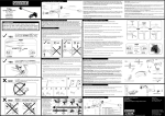
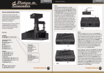
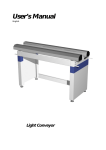
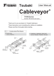
A Picture to Remember Anamorphic Lens Cinomorph P-100R Anamorphic Lens Setup Instructions Cinomorph P-100R Bringing the lens into the use: STEP 1 Lift the lens up and flip it upside down in a stand. By using the L-wrench, 3 mm remove the delivery lock screws of prisms from bottom plate (Fig 1-a). After this carefully remove the front element by releasing the four cap screws (Fig 1-b). Put the front element in a safe place waiting for the further use. After this remove the bottom plate of housing by releasing the four screws on the bottom plate (Fig 1-c). a) c) c) a) c) c) b) b) b) b) Fig 1 Fig 2 INSTALLATION INSTRUCTIONS Parts list: Carefully remove and unwrap all the contents of box. Referring to the parts list, make sure you have everything needed to proceed with the installation of the lens. If any parts are missing, contact Prismasonic immediately. Inspect the lens to make sure there are no shipping defects. If you notice a problem with the lens itself, or the lens’ mechanical system, contact Prismasonic immediately. STEP 2 Now carefully take off the plastic cover sheets from both sides of both lenses (Fig 2). Remove also the cover coats from both IR windows of motor box. STEP 3 Insert the bottom plate back to the housing and prepare to affix the four screws (Fig 3) with Lwrench, 3mm. Tighten the screws securely. Lens Unit Table Stand Power Cord Power Converter Remote Controller L-Wrench, 3 mm L-Wrench, 4 mm Instruction Manual At this point, do not yet insert the front element back to its place, since it has to be unassembled while setting up the system. Flip the lens back upright in a stand. Your lens is now ready for the setting up! Fig 3 Anamorphic Lens Setup Instructions Cinomorph P-100R Anamorphic Lens Setup Instructions Cinomorph P-100R Setting up the system: STEP 4 Make sure the projector is turned on. It is helpful to have a picture that fills the entire panel of 16:9 projector. With a 2.40:1 source material the vertical expand is good to be performed to the picture at this step. (Fig 4) Fig 7 STEP 8 Take the front element, remove the cover sheets and secure it to the lens body using the four screws (Fig 8). Fig 4 Now manually adjust the lens in a stand. Make sure the entire beam fits centered within the two lenses (Fig 5). Lower, raise and tilt the lens until the desired height and angle is reached. Make sure the image is now rectangular and still symmetrically in the center of the screen. You slightly have to zoom in the picture after front element installation. Also now adjust the focus and picture in a ‘in’ mode to achieve the optimum settings, and note these settings as for future reference. Fig 8 NOTE: The optimum symmetry for the projected picture can only be found by tilting the lens to the direction of the beam a) Fig 5 front view rear view Fig 6 rear view STEP 7 If the sides of picture are not opening/closing synchronously to each other when switching the modes, tune the terminal screws to where the prisms stop after pressing the ‘out’ button (Fig 7). Open the cap screw of the prism which had a shorter travel, and close the cap screw of that prism, which had a longer travel until both sides of picture are opening and closing synchronously to each other. Now carefully adjust the focus of projector. Also make sure the image is symmetrically in the center of the 2.40:1 screen. STEP 5 First move the prisms to the ‘out’ mode using the supplied remote controller until the prisms stop. Carefully position the lens with a stand in front of the projector, with the small opening closest to the projector lens and the large opening pointing towards the screen. front view STEP 6 Using the remote control, press ‘in’ until the prisms stop again. The tuning of picture width can be accomplished manually by adjusting the cap screws inside the lens to match your screen perfectly on both sides. NOTE: Tuning is done with the cap screws to where the prisms stop after turning the prisms to the ‘in’ position (Fig 6) Fig 9 b) STEP 9 In case the friction based lens height (Fig 9-a) or the tilt (Fig 9-b) adjusting mechanism become too loose, it is possible to get them tightened with the set screws of stand drums on both sides of lens. Use the L-wrench, 4 mm for tightening the screws. You’re done. Enjoy your new 2.40:1 picture! Maintenance: Your Cinomorph lens was designed to require very minimal cleaning. It is best to only wipe the lens housing with a clean, damp, soft cloth when needed. Cleaning the optics: Only use optically safe lens cleaning solutions and a clean, lint-free cloth certified for cleaning of lens materials. In order to clean the optics from both sides, the bottom plate can be temporarily removed.