1
Tsubaki
User Manual
Cableveyor
®
TKMKSeries
(formely TKM Series open type)
Thank you for your purchase of a Tsubaki Cableveyor.
These instructions cover everything from delivery to installation.
Please read them thoroughly before starting.
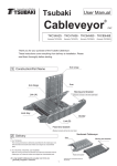
1 Construction/Part Name
1.1 TKMK47H28
1.2 TKMK65H42, TKMK95H58, TKMK125H72
(formerly TKMO650, TKMO950, TKM1250)
(formerly TKMO475)
Arm
Arm
Long stay
Link
Link
Connecting pin
Lock stay
Locking bolt
Bracket link
Bracket link
Mounting bracket
Mounting bracket
1
2 Delivery
Your Cableveyor will be delivered disassembled if the number of links exceeds the following:
TKMK47H28: 84 links
TKMK65H42: 64 links
TKMK95H58: 40 links
32 links
16 links
8 links
TKMK125H72, R260 or less
R340 or R380
R500
3 Cableveyor Connection
(1) TKMK47H28
Overlap the points to be connected and firmly press them
together with your hands or tap them together with a plastic
hammer until you hear a click. Bend the connected area
several times to ensure that the points were connected
properly.
(2) TKMK65H42, TKMK95H58, TKMK125H72
Ensure the points to be connected are facing the same
direction. Overlap these points and insert locking bolts
into the center holes. Use a tool that matches the
grooves in the locking bolts.
Locking bolt
To connect
To disconnect
Use an Allen wrench to turn the locking bolt clockwise 90°
until the arrow aligns with the LOCK mark. Bend the
connected area several times to ensure that the points were
connected properly.
Allen wrench sizes
TKMK65H42:
Nominal 5, for M6 bolts
TKMK95H58:
Nominal 6, for M8 bolts
TKMK125H72:
Nominal 8, for M12 bolts
4 Opening the Arms
The arms feature a hinge on both ends of the lock stay.
Insert a flat-head screwdriver between the link and hinge to
open the arm.
Hinge
Link
2
5 Attaching Dividers
Vertical dividers are designed to attach to the lock stay, but not to the
arm side (forming a loose fit). Attach the vertical dividers so that the
product name on the side of the divider is on the arm side.
Vertical
divider
Vertical dividers
Loose fit
End stopper
(Not needed for
TKMK47H28)
Horizontal
divider
Full vertical and horizontal height
separation
Part name
(e.g. 0475M)
Partial vertical and
horizontal height separation
Locking groove
6 Closing Arms
Tap the arms with a plastic hammer to close.
7 Attaching Brackets
Attach brackets to links designed for bracket attachment.
(1) TKMK47H28
The brackets and bracket links are connected using the
accompanying connector pins. Pass the connector pin through
the hole and push in the center pin to fix.
(2) TKMK65H42, TKMK95H58, TKMK125H72
The brackets and bracket links are attached using the
accompanying hexagonal bolts. When installing the
Cableveyor into the equipment, it is best to temporarily affix
the bracket to the equipment itself, then insert the cables/
hoses and connect the Cableveyor and brackets.
Connecting pin
(as delivered)
Bolt/Nut
(included)
Push in
8 Attaching Glide Shoes (for long span applications)
Lightly tap the glide shoes with a plastic hammer to insert the
glide shoes into the links on inner radius of the Cableveyor. (*To
remove, insert a flat-head screwdriver between the link and
glide shoe and twist.
(1) TKMK47H28
(2) TKMK65H42, TKMK95H58, TKMK125H72
Inner radius
Inner circumference
3
9 Attaching and Removing Lock Stays
Use a plastic hammer to attach lock stays to the links. Grip
the lock stays with a monkey wrench and twist to remove.
(On long span applications, remove the glide shoes first
before beginning.)
10 Disassembling Cableveyors
To disassemble, perform the opposite of the assembly
steps. For TKMK47H28, remove the arms and lock stays
around the area to disassmble, then insert a flat-head
screwdriver between the links and twist.
11 Cautions When Handling
Pretension and sag may appear in the free span depending
on the application. However, if selected within Tsubaki’s
performance graph then there will be no problems with use.
Moving end bracket
Fixed end bracket
Guide rail
1. Machine travel end installation height (H’) should be
Cableveyor height H + (10-30).
6. Avoid using wire plate jackets as they are easily
damaged.
2. Cableveyor installation space (h) should be H + 100.
7. Cables/hoses wear easily when used stacked onto of one
another. Lay horizontally or use horizontal dividers.
3. Install a guide rail.
8. Set cables and hoses in the Cableveyor so that they
have some play, and clamp both ends.
4. The difference in attachment face heights (ε)
between fixed and moving end brackets should be
less than 6mm.
5. Use travel cables/hoses with excellent bending and
wear properties.
9. Remove foreign matter from guide rails, as it may cause
damage.
10. The following are shipped unassembled and will require
assembly when installing the Cableveyor.
・Bracket set (attaching links + brackets and necessary
parts)
・Dividers
4
Issued October 1, 2012
©Tsubakimoto Chain Co.