1
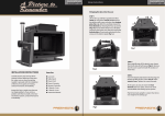
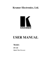
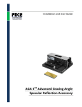
A Picture to Remember INSTALLATION INSTRUCTIONS Carefully remove and unwrap all the contents of box. Referring to the parts list, make sure you have everything needed to proceed with the installation of the lens. If any parts are missing, contact Prismasonic immediately. Inspect the mount to make sure there are no shipping defects. If you notice a problem with the mount itself, or the mount’s mechanical system, contact Prismasonic immediately. Ceiling Mount Cinomount U-100P Ceiling Mount Setup Instructions Cinomount U-100P STEP 1 Flip the projector upside down on a table. Depending on the thread size and position on a projector body use either set screw, m4 x 16, m4 x 25, m5 x 16, m5 x 25, m6 x 16, m6 x 25 to connect the threaded washer to the projector body. First set the threaded washer to its place. Now attach the set screw with a correct sized L-wrench from the top, through the correct screw thread of threaded washer, to the projector body until the heel of set screw is slightly below plane of the washer top surface. Leave the m6 thread in center still unused. Finally tighten the threaded washer against the projector body by rotating it clockwise. Make sure that after tightening the washer the head of set screw is not above the top surface of threaded washer. If the screw threads of projector body are on different planes, use the washer, m6 x 25 to make the height of each threaded washer on plane to each other, as presented in a zoomed Fig 1. Part List: Assemblies ceiling box (pre assembled module) pipe holder (pre assembled module) Custom Aluminum Parts base plate extension washer (2 pcs) lens grip (2 pcs) pipe rod 180 mm (6 pcs) rod 270 mm (4 pcs) square nut (10 pcs) threaded washer (4 pcs) Hardware Cap Screw, M6 x10 (16 pcs) Cap Screw, M6 x 12 (4 pcs) Cap Screw, M6 x 16 (4 pcs) Cap Screw, M10 x 90 Nut, 10 mm Set Screw, M4 x 16, M4 x 25 (both 4 pcs) Set Screw, M5 x 16, M5 x 25 (both 4 pcs) Set Screw, M6 x 16, M6 x 25 (both 4 pcs) Set Screw, M10 x 90 Washer, M6 x 25 (8 pcs) ceiling plate corner pole (4 pcs) black window (4 pcs) mask plate pipe holder, top (2 pcs) skt cap screws set screws a) 181 mm pipe plate pipe plate holder (2 pcs) pipe holder,bottom1 (2 pcs) pipe holder,bottom2 (2 pcs) skt cap screws set screws Fig 2 Tools L-wrench, 2 mm, 2.5 mm, 3 mm L-wrench, 4 mm, 5 mm, 8 mm Spanner Wrench, adjustable b) c) m5 washer, m6 x 25 c) m4 a) c) m6 m6 b) threaded washer c) b) Fig 1 STEP 2 Referring to Fig 2-a, attach the 4 pcs of rod 180 mm in two pairs, so that every two of them are in a row with each other and locating crosswise in relation to the projector’s optics. Position the seam of each pair as center to the projector’s optics as possible. Before inserting the skt cap screws, m6 x 10 to attach the rods to the threaded washer, string the square nut from side to the slot of each rod exactly as shown in Fig 2-a. (In order to achieve the best strength against the upward force, these square nuts are good to be located close to the threaded washers.) Now tighten the each screw securely with L-wrench to the center thread of each threaded washer. After this prepare to attach the rod 270 mm with skt cap screws, m6 x 10 to the square nuts, which were just pre assembled to the slots of each rod 180 mm, exactly as shown in Fig 2-b. Again, position both rods as symmetrically related to the projector’s optics as possible. And again, before inserting the screws, string 4 pcs of square nuts into the slots of each rod 270 mm so that they are symmetrically locating related to the projector’s optics, and having around 181 mm perpendicular distance to each other as shown in Fig 2-b. After positioning the square nuts on both rod 270 mm, tighten the cap screws securely using L-wrench against the pre assembled square nut of each rod 180 mm. Ceiling Mount Setup Instructions Cinomount U-100P Ceiling Mount Setup Instructions Cinomount U-100P In case the projector had an asymmetric optics location, the rod layout can be designed as shown in a Fig 3-a. Fig 3-b shows the rod layout for the projector which has the body screw threads on a very long distance to each other. 181 mm 181 mm Fig 3 a) b) Tighten the skt cap screws, m6 x 10 on the slot of base plate to the pre assembled square nuts on the slots of rods 270 mm. In case the base plate do not reach each square nut of rod 270 mm they will be left yet as they are (Fig 4-b). a) Fig 4 b) NOTE! Depending on the projector and the used lens model the correct location for both rod 180 mm at this step has to be checked case by case, so that the lens grips can be positioned at correct places (Fig 6), which will correspond for the optimum lens location in front of the projector’s optics. b) STEP 3 Now prepare to attach the base plate on the crosswise inserted bars so that it is symmetrically locating in relation to the projector’s optics, exactly as shown in Fig 4-a. Make also sure the base plate is parallel with the projector’s front edge, and ,depending on the setup, the distance between the front edges of base plate and projector is few centi meters (Fig 4-b). NOTE! Before attaching the base plate it is good to start to design the cable management at this point. The power cable with two inputs and one output is enough to power up both the projector and the lens. The output of the cable is fed from below the base plate through the hole marked with the circle in Fig 4-a. On the other hand a good place for the double input cable terminal is for example at the spot marked with a quadrangle in Fig 4-a. Make sure the signal cable (HDMI or other) is now also fed from below the base plate through the hole marked with the circle in Fig 4-a. STEP 4 Next, insert the 2 pcs of rod 180 mm on the base plate exactly as shown in Fig 5-a. The bars are attached with skt cap screws, m6 x 10 to the screw threads of base plate locating on the back end of plate. Also now if there is some back corner(s) of base plate yet to be attached to the crosswise bars (Fig 5-b), it is now connected to the base plate with skt cap screws, m6 x 16 using the rod 180 mm and the extension washer exactly as shown in a Fig 5-b. String still one square nut to both rod 180 mm and tighten the screws carefully with Lwrench. Now the base plate is attached to the projector body securely from four spots. Fig 5 a) STEP 5 Attach the two lens grip parts next exactly as shown in Fig 6. The skt cap screw, m6 x 16 connects both lens grip to the screw threads locating on the front of the base plate, while the skt cap screws, m6 x 10 attach the grip parts to the pre assembled square nuts of both rod 180 mm. The correct lens grip position related to the projector’s optics can be checked with the lens. In order to be able to have a proper tilt adjustment to the lens, it is good to leave 1-2 cm gap between the lens entrance and the projector’s optics. Fig 7 shows the front and side views of setups at this stage for the case of projector of asymmetric optics location (Fig 7-a) and the case of projector with a body screw threads on a long distance to each other (Fig 7-b). In case the rod 180 mm is too short to reach the crosswise bars, the rod 270 mms is used for extending the lens grips, exactly as pointed with arrows in Fig 7-b Fig 6 Ceiling Mount Setup Instructions Cinomount U-100P Ceiling Mount Setup Instructions Cinomount U-100P STEP 7 Next insert the pipe exactly as shown in Fig 9. The set screw m10 x 80 is screwed from the enter thread of pipe holder through the hole pair (locating at 48 mm from edge) of pipe to the exit threads of pipe holder, so that there will be a few millimeter passage for the set screw on both ends of pipe holder. After this by using L-wrench, tighten the pair of set screws m10 x 10 on both sides of pipe holder (circled in a Fig 9), so that the pipe becomes perpendicular to the base plate. NOTE! Before attaching the pipe make sure all the cables have been routed through the pipe. Fig 9 Fig 7 b) a) STEP 8 Remove the cover sheets from outside surfaces of black windows of the ceiling box assembly. After this release the skt cap screws from corners by using the L-wrench. Now the ceiling box assembly will separate into the two pieces as shown in a Fig 10. Fig 10 STEP 6 Now attach the pre assembled pipe holder module to the base plate with 4 pcs of skt cap screws, m6 x 12, exactly as shown in Fig 8-a. Tighten the screw securely using L-wrench, after which tighten the pair of set screws m10 x 10 on sides of pipe plate (circled in a Fig 8-b), so that the pipe holder module will be in parallel to the base plate. In case of projector of asymmetric optics location, for attaching the pipe holder module (Fig 8-c), choose the screw threads on base plate, which are more in the center of gravity spot. side view side view cables cables c)c) a) bottom view Fig 11 a) Fig 8 b) bottom view b) Ceiling Mount Setup Instructions Cinomount U-100P Ceiling Mount Setup Instructions STEP 9 Install the upper part of ceiling box assembly to the correct location on a ceiling (Fig 11) (installation parts not included). The four oval shaped slots for the screw installation is circled in the bottom view of Fig 11. Please consult the professional installer if you do NOT know an appropriate way to attach heavy loads to your ceiling material! Cinomount U-100P STEP 11 Referring to Fig 13 now insert the lower part of ceiling box back to its place by tightening the four skt cap screws with L-wrench, while stringing the cables through the ceiling or through cable routing slot of ceiling plate. Corner poles of ceiling box assembly may have to be loosened by opening them slightly from the ceiling plate. This helps the black windows to fit smoothly to their places in between the corner poles. All the cables can be routed from ceiling box to any direction on the ceiling or through the ceiling. The route direction to cables will be defined by the orientation of cable routing slot shown in the bottom view of Fig 11. In case of sloping ceiling, the orientation between the cable routing slot and the pipe holders, top (circled in the side view of Fig 11) has to be chosen so that the pipe holders are to the direction of the slope, exactly as shown in Fig 11-b. This orientation will allow pipe to hang without restraint, perpendicularly towards to the ground. The pipe holder position related to the cable routing slot can be switched by releasing the four skt cap screws from the top of ceiling plate. Fig 13 Fig 12 a) b) STEP 10 Now lift the projector with the mount assembly up to the ceiling box and insert the skt cap screws m10 x 90 through the holes of both pipe holder; top and the pipe (locating at 33 mm from edge). Tighten the screw securely against the nut 10 mm using the L-wrench and hex socket. Before lifting the system up, insert the lower part of ceiling box laying on the lower pipe holder assembly exactly as shown in Fig 12. In case of sloping ceiling make sure the extra opening notch of mask plate is pointing to the direction of slope, exactly as shown with a quadrangle in Fig 12-b. After the system is hanging freely towards to the ground tighten the set screws m10 x 10 on both sides of upper pipe holders (circled in a Fig 12-b). NOTE ! Before lifting the projector with the mount assembly it is now time to do the final cable management by routing the cables through the ceiling or on the ceiling via the cable routing slot of ceiling box. NOTE ! Also now it is a moment to turn ON the projector for the first time, and align the 16:9 picture exactly to the center of the screen. If the system has to be rotated for centering the picture, it is done by turning the whole system on a ceiling. The oval shaped screw slots of ceiling plate (bottom view of Fig 11) allow to make this fine tuning. Also the fine tilting of projector to both directions can be operated by playing with the set screw pairs presented in Fig 8-b and Fig 9. STEP 12 Finally insert the lens, depending on the model, from above or below into the lens grips. (Fig 14-a and Fig 14-b). The stand plate of the lens has to be temporarily removed in both cases. In case of short pipe combined with the Cinomorph C100M / C-100R lens, also the lens grips have to be temporarily removed from the mount assembly for stringing the lens rails into the grips. This is because the short pipe may not allow to have enough space to string the long lens poles from above into the lens grips. (The lens grips can be safely removed from the mount if the user manual has been carefully followed during the assembly steps). After finding the correct height for the lens system by sliding the lens rails on the grips, the both set screws of both lens grips are tightened securely with the L-wrench (zoomed part of Fig 14-a). Also remember to attach the temporarily removed stand plate of lens back into the place. Now make the final tilt adjustments to the system by playing with the set screw pairs presented in Fig 8-b and Fig 9, after which the pipe is completely locked by tightening the pair of set screws with L-wrench on both sides of pipe holder assembly. (circled in the zoomed Fig 14-b) NOTE! Minimum recommended drop from nonsloping ceiling to projector’s bottom is 25 cm You’re done. Enjoy your new 2.40:1 setup! a) Fig 14 b)