1
Date: Oct. 17, 2012
RENESAS TECHNICAL UPDATE
1753, Shimonumabe, Nakahara-ku, Kawasaki-shi, Kanagawa 211-8668 Japan
Renesas Electronics Corporation
Product
Category
Title
MPU/MCU
Document
No.
TN-RX*-A023A/E
Note on Using Multi-Function Timer Pulse Unit 3
(MTU3) Interrupts
Information
Category
Technical Notification
Lot No.
Applicable
Product
RX 62T Group, RX 62G Group,
and RX 63T Group
All lots
Rev.
1.00
RX62T Group User’s Manual: Hardware
Reference
Document
RX62G Group User’s Manual:
Hardware
RX63T Group User’s Manual: Hardware
Thank you for your valued patronage and best wishes for your continued success in business.
We would like to inform you of a note on using multi-function timer pulse unit 3 (MTU3) interrupts. Take the appropriate
measures as described in section 1.2 when necessary.
1.
Note on Clearing Status Flags in Timer Status Register (TSR)
1.1 Description
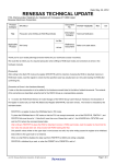
If a status flag (*1, *2, and *3) in the timer status register (TSR) is cleared to 0 at a certain timing, no MTU3 interrupts may be
issued to the CPU after that. The following gives the details.
The specified procedure for clearing a flag is reading 1 from the flag and then writing 0 to the flag as described in the manual
(*4). However, if the interrupt is generated after 1 is read from the corresponding flag before the flag is cleared to 0, the
corresponding flag is not cleared but remains 1, thus disabling the clear-to-0 instruction as shown in the figure below. Once
this condition occurs, if the interrupt is generated while the status flag is 1, the interrupt status flag in the ICU (IR bit in the IR
register) is not set to 1 and thus any interrupt to the CPU is ignored (*5). Consequently, if an interrupt is generated during the
above period or after that before the status flag is reset next time, the interrupt is not processed. To prevent this, use the
procedure that is given in section 1.2 to clear a status flag.
Flag setting request generated
ICLK
TCNT
Timing of reading 1 from corresponding flag in TSR
Timing of writing 0 to corresponding flag in TSR
Timing of generation of condition to set
corresponding flag in TSR to 1
1 is read.
0 is written.
Request flag setting
Request flag setting
Remains to be set
State of corresponding status flag in TSR
State of corresponding IR flag in ICU
No interrupt request
*1: TGFm flag (input capture/output compare flag m) (m = A to F)
*2: TCFj flag (overflow/underflow flag j) (j = V or U)
*3: CMFn5 flag (compare match/input capture flag n) (n = U, V, or W)
*4: Page 479 of RX62T Group User’s Manual: Hardware Rev. 1.3
*5: Section 16.4 on page 613 of RX62T Group User’s Manual: Hardware Rev. 1.3
(c) 2012. Renesas Electronics Corporation. All rights reserved.
Page 1 of 2
RENESAS TECHNICAL UPDATE TN-RX*-A023A/E
Date: October 17, 2012
1.2 Permanent Countermeasure
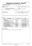
An interrupt request is ignored while the corresponding flag in the TSR is 1; to enable the interrupt again, clear the
corresponding flag and take the preventive measures through software as shown in the flowchart below.
Interrupt caused by
corresponding source
Clear the corresponding flag in MTU3.TSR.
Confirm the corresponding
flag status again.
0
1
Set the IR .IR bit of ICU to 1.
End
1.3 Corrections to the Hardware Manuals
The content of this update is going to be added as a note to the hardware manuals when they are revised next time. The
related hardware manuals and their revision numbers and ICU section numbers are listed in table 1.
Table 1 Related Documents and ICU Section Numbers
ICU Section
Group
Related Documents
Rev.
Control Code
Number
RX62T
RX62T Group User’s Manual: Hardware
1.30
R01UH0034EJ0130
11
RX62G
RX62G Group User’s Manual: Hardware
1.00
R01UH0321EJ0100
11
RX63T
RX63T Group User’s Manual: Hardware
1.00
R01UH0238EJ0100
14
Page 2 of 2