Transcript
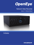
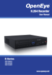
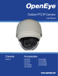
CA-D4000 | Camera Tester
Quick Guide
This quick operation guide is a quick reference for users to install and operate the D4000 camera tester and only provides basic information on the settings and operation. Before attempting
to connect, configure and operate the tester, please read the user manual thoroughly.
Connections
Box Contents
Video in
Video out
Stylus storage slot
LAN / PoE out
LAN / PSE in
D4000 Tester
BNC Cable
Network Cable
Power indicator
Data TX/RX indicator
Micro SD slot
Light sensor
USB
LCD screen
Li-ion Battery
Soft Carrying Case
DC 12V Adapter
UTP Terminal Block
CD
Quick Start Sheet
Shift/PTZ control keys
Main power switch
Audio out
Audio in
Dimensions
ESC
Charging indicator
Start/Enter/Snapshot
Speaker
UTP cable tester
99.3 mm
38 mm
DC 12V power adapter
170 mm
RS-485 terminal block
Item
LAN / PoE out
LAN / PSE in
Micro SD slot
USB
Video in
Video out
Stylus storage slot
Power indicator
Data TX/RX Indicator
Light sensor
LCD screen
Powering On / Off
Shift/PTZ control keys
To power on the IP Camera Tester:
1. Set the Main Power Slide Switch on the side to “ON” position.
ESC
2. Press the Start Key and hold for 3 seconds. The Power Indicator LED (above the
screen) will light.
3. When the Tester powers on, a loading bar will display on the screen for 10 seconds and
the Data TX/RX Indicator LED will blink.
Start/Enter/Snapshot
4. The Home Screen will display within 50 seconds.
Main power switch
Audio out
Audio in
Charging indicator
Charging the Battery
The IP Camera Tester uses a rechargeable Li-ion battery pack that takes approximately four
hours to charge, and provides the Tester with up to three hours of operating life.
UTP cable tester
To charge the battery:
1. Plug the included DC 12V adapter in the side of the Tester.
DC 12V power adapter
2. While the battery is charging, the charging indicator light (above the power cable) will
illuminate. When the battery is completly charged, the light will turn off.
23221 E Knox Ave
Liberty Lake, WA 99019
1.888.542.1103
RS-485 Terminal Block
Speaker
A12931
Description
Connect the LAN cable from the PoE-enabled IP
camera.
N/A
Data storage up to 4GB.
Use for firmware upgrades or external storage.
Connect to camera with BNC cable.
Connect to monitor with BNC cable.
Use the included stylus for touch screen operation.
The LED is lit when the power is on.
The LED flashes when the Tester is under operation.
The light sensor detects environmental brightness to
automatically adjust the LCD screen brightness.
3.5” screen displays video and camera setup menus.
Press the arrow keys to navigate the setup icons,
items in a menu, or use the keys to control a connected PTZ camera.
Press to exit a menu without saving or return to the
previous page.
Start: Turn on the Main Power Switch, then press
this key for 3 seconds to start the tester.
Enter: Press this key to enter a sub-menu or save
setup.
Snapshot: When viewing IP camera video, press this
key for an image snapshot. Press the key and the
snapshot menu will open within 5 seconds. Tap Enter
to save the settings of the image.
Switch to on before pressing the Start key.
Connect to a headset.
Connect to a microphone.
The light will stay lit while the battery is charging.
Use a network cable to connect the tester to the
CAT5 UTP terminator for detecting wiring types
(straight/corss) or errors (open, short, miswired) using the wire map displayed on the screen.
Connect the supplied DC adapter.
Connect the RS-485 lines to the terminal block correctly for the dome camera’s PTZ control.
For audio output.
Copyright ©2011 OpenEye. All Rights Reserved. Information contained in this document
is subject to change without prior notice. OpenEye does its best to provide accurate
information but cannot be held responsible for typos or mistakes.
30640AA