1
HPTDC8-PCI
Time to Digital Converter
with 25ps Resolution
cronologic GmbH & Co. KG
Jahnstraße 49
60318 Frankfurt
Rev 3.6.0 as of 2015-11-26
Firmware 7, Driver v3.6.0
User Manual
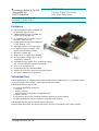
Features
■ 8 NIM compatible inputs on LEMO connectors with 25ps bin size
■ 1 NIM compatible input on LEMO connector with 12.8ns bin size
■ 12 LVCMOS inputs on SUB-D connector with 12.8ns bin size
■ typical deadtime between multiple hits
on one channel <5 ns
■ unlimited number of hits per trigger
■ no dead time due to readout, new
data is acquired during readout
■ 4M Hits/s readout rate
■ 419µs range w. trigger logic enabled
■ 2h range without trigger logic, can be
extended by software
■ adjustable trigger window (size, position of trigger)
incl. common start and common stop mode
■ easy to use windows driver
■ on board storage for calibration data
■ support for up to three event-synchronized boards
■ 5V, 32-bit, 33MHz PCI target device
Intended Use
Typical applications for a HPTDC8-PCI include atomic physics experiments (e.g. momentum imaging, time-of-flight spectroscopy), mass spectroscopy and LIDAR.
The HPTDC8-PCI may not be used
• for medical applications except for
• research
• imaging systems
• medical devices used solely as diagnostic tools
• in military devices
• in conjunction with nuclear materials related to defense or power systems
• for space applications with the exception of fundamental research
The HPTDC8-PCI may not be used for military purposes.
If the HPTDC8-PCI is sold, the above restrictions must be incorporated in any resale contract.
cronologic GmbH & Co. KG
1
HPTDC8-PCI
Time to Digital Converter
with 25ps Resolution
Rev 3.6.0 as of 2015-11-26
Firmware 7, Driver v3.6.0
User Manual
Concepts
The HPTDC8-PCI continuously records the digital waveforms on its inputs similar to a logic analyzer
with an accuracy of up to 25ps.
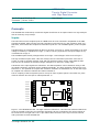
Inputs
The board has nine AC coupled inputs on LEMO series 00 coax connectors compatible to the NIM
signaling standard. Eight of these are high resolution inputs and one is a low resolution input. Furthermore, it has twelve DC coupled low resolution inputs for 3.3V LVCMOS signals (LVTTL compatible).
The NIM inputs are terminated with 50 Ohms to ground. A current of -16mA (equivalent to an input
voltage of -800mV) is identified as a logic 1, and no current (equivalent to an input voltage of 0V)
is identified as a logic 0.
The LVCMOS inputs identify voltages above 2V as logic 1 and voltages below 0.8V as logic 0.
The high resolution inputs have a bin size of 25ps; the low resolution inputs have a bin size of
12.8ns. In order to simplify analysis, high and low resolution inputs use the same data formats.
The time for all channels is stored as integer multiples of a unit time, usually 25ps.
Transitions of the input signals are called hits. The data acquisition can be limited to rising or falling signal transitions. Channels can be enabled individually. The high resolution channels are numbered 0 to 7, the optional DC coupled low resolution channels are numbered 9 to 20 and the single
AC coupled low resolution channel has channel number 8.
The AC coupling of the front panel inputs is set up for short negative pulses. The width of a pulse
must be between 5ns and 3µs to match parameter t pw.
TDC8
sync
channel 1
JP1
JP2
JP3
JP4
JP5
channel 0
+2.5V
+3.3V
channel 2
channel 4
TDC
channel 5
PCI I/O
FIFO
channel 6
channel 7
ext. CLK
onboard
channels 9 to 20
channel 3
JP6
PROM
CLK
+2.5V
channel 8
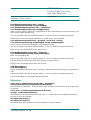
Figure 1: The HPTDC8-PCI card. The high resolution channels 0-7 and the low resolution NIM-channel 8 are located on the left. Low resolution channels 9-20 are connected to the 26-pin ribbon cable connector on the right side. The 10-pin ribbon cable connector at the top is used to connect
and synchronize several HPTDC8-PCI.
cronologic GmbH & Co. KG
2
HPTDC8-PCI
Time to Digital Converter
with 25ps Resolution
Rev 3.6.0 as of 2015-11-26
Firmware 7, Driver v3.6.0
User Manual
Rollover
The data format for a hit contains 24 bits of timing information, which is sufficient for a 419µs time
interval at 25ps resolution. The HPTDC8-PCI is collecting data continuously. Whenever the 24 bit
counter rolls over a rollover marker is inserted into the data stream with an additional 24 bits for
the time measurement (thus allowing measurements of up to ~2h). The time interval between two
rollovers is called a frame. If there is no hit between two consecutive rollover markers only the last
marker appears in the output. However, it is guaranteed that that at least one rollover is output
before the 48 bit counter overflows. Using this information measurements with infinite range can
be performed if grouping is disabled.
The rollover markers can optionally be suppressed by the driver if grouping is enabled in order to
simplify the data format and reduce the data rate for applications that do not need timing information that spans multiple groups. Without grouping enabled rollovers are always output.
Trigger
An arbitrary input channel can be selected as trigger input. A trigger condition occurs for a signal
transition on that input. The time of the trigger condition can be used to group the input data (see
below).
Triggers can be rearmed automatically after a programmable delay, after the group associated with
the trigger is finished.
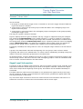
Groups
Hits can be merged to groups (or events in HEP nomenclature). A group will contain hits that occurred within a certain time interval relative to a trigger. Both, the start and end point of the interval can be configured within a range of -209.7µs to 209.7µs. Figure 2 shows a typical data acquisition scenario in triggered mode. The size of the acquisition window is set by the configuration parameters GroupRangeStart and GroupRangeEnd. The falling edge of the trigger signal is used
(TriggerEdge falling).
Trigger
Data
GroupRangeStart
GroupRangeEnd
Figure 2: Data acquisition in triggered mode. Hits within the group's range (green) are acquired,
hits outside that range (red) are rejected.
Data within a group has timing values relative to the trigger event's time. Hits can be assigned to
multiple groups. If a new trigger event occurs inside the range of a group one of three behaviors
cronologic GmbH & Co. KG
3
HPTDC8-PCI
Time to Digital Converter
with 25ps Resolution
Rev 3.6.0 as of 2015-11-26
Firmware 7, Driver v3.6.0
User Manual
can be selected:
1 No trigger is issued and the trigger event is recorded as a hit on the trigger channel if data taking for this channel is enabled.
2 A new trigger is issued, the previous group is ended and data in the overlapping range is assigned to the new group.
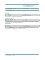
3 A new trigger is issued and data in the overlapping range are assigned to both groups possibly
including the trigger event.
The range of a group is limited to 419.4μs.
Figure 3 displays the three types of behavior. On top, a trigger is suppressed using the configuration parameter TriggerDeadTime. In the middle of Figure 3, a group is ended by a consecutive
trigger. A new group is started. Both groups' ranges are truncated. This behavior is enabled using
the configuration parameter AllowOverlap false. Figure 3 (bottom) shows the case of overlapping
groups (AllowOverlap true). Hits inside the overlapping region of both groups are assigned to
each group, the timing value is calculated with respect to the corresponding trigger time.
If grouping is disabled, the timing value for a hit is an unsigned integer relative to the last rollover
marker.
A group in the data stream ends with the beginning of a new group or with a rollover marker.
If grouping and rollovers are enabled there is a rollover marker immediately preceding each group
marker, even if two consecutive groups start in the same frame.
As described before, a trigger deadtime can be set in order to suppress consecutive triggers in the
chosen timing interval. This can be used to avoid overlapping groups or create an intentional dead
time to remove unwanted data from the data stream.
Signal Level Information
If grouping of data is enabled, input transitions, that occur outside a group are not recorded. If the
signal has no transition within the group, the level of the signal is unknown. Therefore the signal
levels can be output at the beginning of each group. This feature can be enabled individually for
each board.
If multiple TDCs are used the level information is not guaranteed to appear directly at the beginning of a group for all TDCs. Level information for each board is guaranteed to appear before the
first signal transition of that board.
Any errors that might cause hits to be lost can cause incorrect level information. Once there is a
another hit received on a channel the level information will be correct again.
cronologic GmbH & Co. KG
4
HPTDC8-PCI
Time to Digital Converter
with 25ps Resolution
Rev 3.6.0 as of 2015-11-26
Firmware 7, Driver v3.6.0
User Manual
TriggerDeadTime
Trigger
Data
GroupRangeStart
GroupRangeEnd
Group1
Group2
Trigger
Data
GroupRangeStart
GroupRangeEnd
GroupRangeStart
GroupRangeEnd
Group1
Group2
Trigger
Data
GroupRangeStart
GroupRangeEnd
GroupRangeStart
GroupRangeEnd
Figure 3: The three different types of grouping described in the text.
cronologic GmbH & Co. KG
5
HPTDC8-PCI
Time to Digital Converter
with 25ps Resolution
Rev 3.6.0 as of 2015-11-26
Firmware 7, Driver v3.6.0
User Manual
Data Format
The readout data is a stream of 32 bit words in little endian byte order. Each word represents a
signal transition on an input or a special marker.
Falling transition
31-30
29 – 24
23 – 0
10
channel
transition time
The transition time is a 24 bit signed integer when inside a group or an unsigned integer otherwise.
Rising transition
31-30
29 – 24
23 – 0
11
channel
transition time
The transition time is a 24 bit signed integer when inside a group or an unsigned integer otherwise.
Error with channel information
31-30
29 - 24
23 - 16
01
channel
error
Error numbers below 128 are lost hits.
15 - 0
count
If the bit with weight 64 is set and multiple boards are present, applications should reset the data
acquisition if the trigger channel is in the group the error occurred in.
Any errors that might cause hits to be lost can cause incorrect level information. Once there is a
another hit received on a channel the level information will be correct again.
Error Number
0
16
32
96
112
160
128
129
255
Source
FPGA
SOFT
FPGA
FPGA
SOFT
TDC
FPGA
FPGA
SOFT
Description
hires data lost due to fpga fifo overflow
data lost due to software buffer overflow
lores data lost due to fpga fifo overflow
triggers lost due to fpga fifo overflow
trigger lost due to software buffer overflow
TDC chip error, possibly hit lost
unknown error, should occur only for prototype
FPGA fifo empty
boards might be out of sync, user should reset the board
Group
31 - 28
27 - 24
23 – 0
0000
Id
trigger time
The time values of the following hits should be added to the trigger time to obtain the absolute
time of the transition. The id currently is always 0 but could be used to identify multiple trigger
conditions in future versions.
cronologic GmbH & Co. KG
6
HPTDC8-PCI
Time to Digital Converter
with 25ps Resolution
Rev 3.6.0 as of 2015-11-26
Firmware 7, Driver v3.6.0
User Manual
Rollover
31 - 24
23 – 0
00010000
upper 24 bits of time stamp
The time between two rollovers is called a frame.
Level information
31 – 27
26 - 21
20 -0
00011
n
Level
At the beginning of a group the levels of the input signals can optionally be output. One word contains the levels of 21 inputs beginning at channel n.
Resolution
31 – 24
23 – 0
00100000
bin size in fs (25000)
This word should be added once at the beginning of each output file to describe the size of a timing
bin. Currently there exist two types of TDCs: Most have 25.00000ps resolution and starting with
serial number 9.50 some TDCs have 25.117348ps resolution.
cronologic GmbH & Co. KG
7
HPTDC8-PCI
Time to Digital Converter
with 25ps Resolution
Rev 3.6.0 as of 2015-11-26
Firmware 7, Driver v3.6.0
User Manual
Configuration File
TDC, FPGA and the driver software are configured by text based configuration files that can also
contain calibration data.
Any number of configuration files can be read in with the newer configuration overriding the older
ones. This allows to have configuration files that each describe individual boards, experiment setups and readout situations and combine them as desired.
Configuration files consist of independent lines that can appear in any order. Each line configures
zero or one parameter. If the same parameter appears multiple times in a set of configuration files
the last occurrence is used.
Lines starting with a sharp “#” are comments and are ignored by the driver.
Anything behind a double slash “//” to the end of a line is treated as a comment.
There may be any number of empty lines.
All other lines consist of a parameter name and a value. Both, values and parameter names, are
case insensitive.
Values
Values can have different types as follows. If no value is specified a default value is loaded from
the on board PROM.
Boolean
A value that is either true or false. The values “1”, “t”, “true”, “on”, “enable” and “enabled” are recognized as true. The values “0”, “f”, “false”, “off”, “disable” and “disabled” are recognized as false.
Integer
Any integer in decimal base such es “5”, “023” or “-1”.
Time
A floating point number in C-notation such as “5”, “5.2”, “1.7e-3” followed by a time unit. Allowed
units are “s”, “ms”, “us”, “µs”, “ns”, “ps” and “fs”.
Channel mask
A value of this type defines a set of channels that the parameter applies to. The format is a list of
ranges or individual channels separated by commas. A range consists of a lower and upper channel
separated by a minus. The lower and upper bound are included in the range. Examples are „1“ or
„7, 9, 14“ or „1-4,15“. To include all channels use „0-20“. To disable all channels use „no“ or
„none“
Edge
An input transition. The value “falling” denotes a transition from a higher electrical potential to a
lower potential. “rising” denotes the opposite transition.
cronologic GmbH & Co. KG
8
HPTDC8-PCI
Time to Digital Converter
with 25ps Resolution
Rev 3.6.0 as of 2015-11-26
Firmware 7, Driver v3.6.0
User Manual
Parameters
Parameters are named with a case insensitive string of alphabetic characters.
Array parameters are followed by “:” and an index.
If multiple TDCs are present most parameter names can be followed by “@” and a number indicating for which TDC the parameter shall be set. Otherwise the parameter is set for all TDCs. Numbering of TDC boards starts with 0.
Additionally, for parameters that can be set channel wise, the name can be followed by “#” and a
number to indicate for which channel the parameter shall apply. Otherwise the parameter is applied for all channels.
cronologic GmbH & Co. KG
9
HPTDC8-PCI
Time to Digital Converter
with 25ps Resolution
Rev 3.6.0 as of 2015-11-26
Firmware 7, Driver v3.6.0
User Manual
General Parameters configurable by the User
name
type
scope
RisingEnable
mask
FallingEnable
default
description
channel
none
Record 0 to 1 transitions for these
channels
mask
channel
0-63
Record 1 to 0 transitions for these
channels
TriggerEdge
edge
global
falling
Trigger on falling or rising edge
TriggerChannel
int
board
0
63
0
Which channel to use as a trigger
OutputLevel
bool
board
false
true
false
Keep track of signal levels
ExternalClock
bool
global
false
true
false
Use external clock source
VHR
bool
global
false
true
true
Enables the TDC's very high resolution mode with a bin size of 25ps. If
disable the bin size is set to 100ps
increasing the TDC's data throughput by a factor of 4, thus increaseing lossfree hit rates (see page 30).
UseINL
bool
global
false
true
true
Use INL correction.
UseFineINL
bool
global
false
true
false
Use better INL correction with
ReadTDCHit(). Disables coarse INL
correction. Should not be set when
using Read().
BufferSize
int
global
16
27
23
Number of bits in the number of hits
in the buffer. 23 Bits provides a buffer of 8MHits
Prescaler
int
channel
1
32
1
For channels 9 to 14: report only
one out of N edges.
cronologic GmbH & Co. KG
min
max
10
HPTDC8-PCI
Time to Digital Converter
with 25ps Resolution
Rev 3.6.0 as of 2015-11-26
Firmware 7, Driver v3.6.0
User Manual
Grouping Parameters configurable by the User
name
type
scope
min
max
default
description
OutputLevel
bool
board
false
true
false
Keep track of signal levels
GroupingEnable
bool
global
false
true
true
Enable grouping
AllowOverlap
bool
global
false
true
false
If a hit falls within multiple groups
copy it to all groups or just to the
last one
TriggerDeadTime
time
global
0
1s
100ms
Time during which no new triggers
are accepted after a trigger
GroupRangeStart
time
global
209.7μs
209.7μs
0
Smallest time value relative to
group marker to be included in
group. (Set negative for common
stop)
GroupRangeEnd
time
global
209.7μs
209.7μs
209.7μ
s
First time value relative to group
marker not to be included in group,
(Set positive for common start)
OutputRollovers
bool
global
false
true
true
Include rollover markers in the data
format. Rollovers can only be disabled if grouping is enabled.
GroupTimeout
time
global
0
1h
200ms
When using multiple boards the
driver assumes that after this time
interval all data from an event has
arrived in system memory.
Ignored for single board setups.
OutputLevel
bool
board
false
true
false
Keep track of signal levels
cronologic GmbH & Co. KG
11
HPTDC8-PCI
Time to Digital Converter
with 25ps Resolution
Rev 3.6.0 as of 2015-11-26
Firmware 7, Driver v3.6.0
User Manual
Other Parameters
These parameters should usually be kept at their default values. They may be used for debugging
or testing or in special usage cases.
name
type
scope
min
max
default
description
DllTapAdjust:0
int
board
0
7
From
PROM
Lookup table for DNL correction
DelayTap:0
to
DelayTap:3
int
board
0
7
From
PROM
(7, 7, 0, 0)
Calibrate very high resolution clock
INL:0
to
INL:1023
int
channel
0
1023
UseClock80
bool
global
false
true
true
MMXEnable
bool
global
false
true
true
Use 64 bit reads in non-dma mode
DMAEnable
bool
global
false
true
true
Copy data using direct memory access. Should remain true for drivers
3.0.1 and newer.
SSEEnable
bool
global
false
true
false
Use 128 bit reads in non-dma mode
ClockDelayPattern
int
board
0
0xffff
0x0800
don't change
to
DllTapAdjust:31
From
PROM
Lookup table for INL correction
Deprecated or Obsolete Parameters
These parameters have been valid in old versions of the driver but should not be used anymore.
name
type
scope
min
max
default
description
SoftwareSync
bool
global
false
true
false
Enable if more than one card is
used, but no external clock source is
present.
TDC8Sync
bool
global
false
true
false
Synchronize a TDC8 and a HPTDC8PCI board.
SyncValidationChannel
int
global
0
21
8
SimulateExternalClock
bool
global
false
true
false
cronologic GmbH & Co. KG
12
HPTDC8-PCI
Time to Digital Converter
with 25ps Resolution
Rev 3.6.0 as of 2015-11-26
Firmware 7, Driver v3.6.0
User Manual
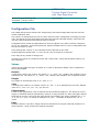
Multiple boards
Unique channel numbers are assigned to each board. The second board will usually start with channel number 21, and the third one with channel number 42. A serial number of the type X.Y is printed on every TDC card (see Figure 4). X denotes the year of production minus 2000, Y is an integer
greater than zero. The card with the lowest number is initialized as the first board, the one with the
next higher number as the second, and the board with the highest number is the third board. For
example: three cards with the numbers 6.7, 7.11 and 6.12 are installed. The first card (with channel numbers 0 to 20) is the one with number 6.7, the second card (channels 21 to 41) is the one
with serial number 6.12 and the third card (channels 42 to 62) is card 7.11.
Figure 4: The card's serial number located on the PCI-interface chip. The first digit denotes the
year of production, the second is a serial number that is unique within that year.
Multiple boards with external clock reference
This is the preferred mode of operation when using multiple boards: a common clock signal is connected to the clock input of each board. This signal must have a frequency of 78.125MHz.
In this case all acquisition modes described above are supported and the additional measurement
error described above is avoided.
Using an external clock, a trigger signal needs to be connected to one TDC board only. This must
be the first board (channels 0 to 20).
In order to enable the external clock source the configuration parameter ExternalClock needs to
be set to true.
The resolution is reported as 25.00000 ps when external clocking is selected, relying on the external clock having the correct frequency.
cronologic GmbH & Co. KG
13
HPTDC8-PCI
Time to Digital Converter
with 25ps Resolution
Rev 3.6.0 as of 2015-11-26
Firmware 7, Driver v3.6.0
User Manual
Calibration
There are multiple levels of calibration: firstly, for the very high resolution mode of the HPTDC8PCI the bin size for the lower two bits of measurement can be adjusted using delay taps inside the
TDC. Secondly, the INL of the data can be corrected using a table lookup in the driver software. It
is an option to use a different bin size after table lookup than before table lookup.
For the table lookup the last ten bits of each timing value are used to index a table that contains
1024 entries for each channel with the last bits of the corrected measurement.
The boards are delivered with calibration data stored in an onboard flash PROM. The driver uses
this data by default. Users can easily create their own calibration data and feed it to the driver or
even program new data to the onboard prom.
When using the Read() method data is return with 25ps quantization with both corrections applied.
When using the ReadTDCHits() method data is returned with 1ps quantization. The average bin
size will still be 25ps, but the information about the individual bin sizes can be preserved. To use
this feature set the “useFineINL” property to “true”.
The reference frequency is determined by a temperature compensated crystal oscillator with the
specifications listed on page 29. The absolute frequency error is dominated by the initial accuracy
and aging of the oscillator. Applications that have stringent requirements for the absolute size of
longer intervals might want to compensate for this error. The frequency can be determined by connecting a pulse per second (PPS) signal from a frequency normal such as a GPS receiver to one of
the inputs and measure the average distance of the pulses.
cronologic GmbH & Co. KG
14
HPTDC8-PCI
Time to Digital Converter
with 25ps Resolution
Rev 3.6.0 as of 2015-11-26
Firmware 7, Driver v3.6.0
User Manual
Programming Interface
The driver API defines the following methods. Both the C++ and the C# syntax is shown. The C#
version can be used in any language that supports the .net platform such as VisualBasic, J# or
managed C++.
Exceptions
Many methods in the API throw exceptions when an error occurs. They all have the type TDCConfigException which is defined as:
class TDCConfigException {
public:
const char * errorString;
};
The error string contains additional information about the nature of the exception.
The application developer can choose to catch the exception and continue with program execution.
Optionally the error string could be logged or presented to the user.
If the exception is not caught the application will be terminated.
Startup and cleanup
void Init()
void Init()
Should be called once before using the TDCManager. Init() detects all present TDC devices, acquires all available information on the those devices and maps the address space for PCI access. It
also reads the „global.cfg“ configuration file if present in the current directory.
Can throw all exceptions that are related to parsing the configuration file.
void CleanUp()
void Cleanup()
Should be called once before exiting the program.
int GetTDCCount()
int GetTDCCount()
Returns the number of HPTDC boards found in the system. From 0 to 3.
Configuration
The TDC and readout configuration is manipulated via a set of methods. The parameters do not
take effect before the Reconfigure() method is called.
If a parameter is set multiple times the last value is used.
cronologic GmbH & Co. KG
15
HPTDC8-PCI
Time to Digital Converter
with 25ps Resolution
Rev 3.6.0 as of 2015-11-26
Firmware 7, Driver v3.6.0
bool
bool
bool
bool
User Manual
SetParameter(const char * config)
SetParameter(string config managed)
ReadConfigString(const char * parameter)
ReadConfigString(string configManaged)
Read in a string with the syntax of a configuration file line as described in the previous section. The
string might contain multiple lines.
Can only be called if the TDC is stopped (states 0, 1 and 2). Throws an exception otherwise.
Returns false if there were illegal parameters or syntax errors. True otherwise.
bool SetParameter(const char * property, const char * value)
bool SetParameter(string propManaged, string valueManaged)
Set the value of a parameter identified by the parameter name.
Can only be called if the TDC is stopped (states 0, 1 and 2). Throws an exception otherwise.
Returns true if successful, false if there was an error.
bool ReadConfigFile(const char * filename)
bool ReadConfigFile(string filenameManaged)
Read in a configuration file.
Can only be called if the TDC is stopped (states 0, 1 and 2). Throws an exception otherwise.
Can also throw exceptions generated while opening or reading the file.
Returns true if successful, false if there was an error.
void Reconfigure()
void Reconfigure()
Writes configuration data to the device. Use after configuration has been changed. This operation is
slow.
Can only be called if the TDC is stopped (states 0, 1 and 2). Throws an exception otherwise.
Throws an exception if a parameters cannot be parsed.
Reflection
const char * GetParameter(const char * parameter)
String GetParameter(string parameterManaged)
Get the value of a parameter. If the parameter does not exist or has not been set an empty string
is returned.
const char ** GetParameterNames(int & count)
string[] GetParameterNames()
Get the names of all parameters that are set. The c++ Version returns the number of elements in
the array in the count variable.
int GetDriverVersion()
int GetDriverVersion()
The lowest three bytes returned are the three digits of the driver Version.
cronologic GmbH & Co. KG
16
HPTDC8-PCI
Time to Digital Converter
with 25ps Resolution
Rev 3.6.0 as of 2015-11-26
Firmware 7, Driver v3.6.0
User Manual
Control
void Start()
void Start()
Configure all TDCs with the parameters set by the methods described in the previous section and
start all TDCs. This method can require several milliseconds to complete when called from state
“NOT_CONFIGURED”. To precisely time the start of the data acquisition call reconfigure() first.
If called from state NOT_CONFIGURED exceptions thrown from reconfigure() can occur.
Also throws an exception if called from state UNINITIALIZED.
void Stop()
void Stop()
Stop taking data and turn off TDCs. The state of the hardware and software queues is undefined after this operation. No additional data should be read out. To get all data in the queues call
Pause() and empty the buffers before calling this method.
The TDC is put into a low power state that can only be recovered by a Start() operation.
Throws an exception if called in states UNINITIALIZED or SHUTDOWN.
void Pause()
void Pause()
Stop taking data. Data already in the hardware and software buffers is left intact and can be read
out. The TDC hardware is kept in a state that allows to resume data acquisition immediately.
Frame counters continue to count.
Throws an exception when called from a state other then PAUSED or RUNNING.
void Continue()
void Continue()
Quickly continue taking data after a Pause(). Buffers are left intact and frame counters are left unaltered.
It is legal to use Start() to resume operation instead.
Throws an exception when called from a state other then PAUSED or RUNNING.
void ClearBuffer()
void ClearBuffer()
Clears all buffers. Only meaningful in state PAUSED.
Throws an exception if called in state RUNNING. Has no effect in other states.
cronologic GmbH & Co. KG
17
HPTDC8-PCI
Time to Digital Converter
with 25ps Resolution
Rev 3.6.0 as of 2015-11-26
Firmware 7, Driver v3.6.0
User Manual
TDCInfo GetTDCInfo(int index)
HPTDCInfo GetTDCInfo(int index)
Get the information on TDC card number index.
Throws an exception if called in state UNINITIALIZED.
Returns an object that contains the following data:
class TDCInfo
class HPTDCInfo
int index;
int channelStart;
int channelCount;
int highResChannelCount;
int highResChannelStart;
int lowResChannelCount;
int lowResChannelStart;
double resolution;
DWORD serialNumber;
int version;
int fifoSize;
int *INLCorrection;
//in .net : int[] INLCorrection;
unsigned short *DNLData; //in .net: short[] DNLData;
bool flashValid;
int bufferSize;
unsigned char boardConfiguration;
index
The index of this board, e.g. 0 for the first board.
channelStart
The number of the card's first channel as initialized by the driver. For example: if two HPTDC8-PCI
card's are present, the second card's channel numbers are usually 21 to 41. That card's first
channel is therefore channel number 21.
channelCount
Total number of channels.
HighResChannelCount
Number of channels with high resolution.
highResChannelStart
Number of first channel with high resolution.
lowResChannelCount
Number of channels with low resolution.
lowResChannelStart
Number of first channel with low resolution.
resolution
The TDC card's bin size of the high resolution channels.
This value can be different for external and internal clocking. The structure should be updated
when changing this parameter.
cronologic GmbH & Co. KG
18
HPTDC8-PCI
Time to Digital Converter
with 25ps Resolution
Rev 3.6.0 as of 2015-11-26
Firmware 7, Driver v3.6.0
User Manual
serialNumber
The card's unique serial number. The highest byte denotes the year of production minus 2000, the
3 lower bytes a serial number.
version
The lowest byte describes the board revision, the next higher byte the firmware revision.
fifoSize
The size of the on board PCI-FIFO in data words.
*INLCorrection
Pointer to an array containing the current INL correction table. The array has a size of 8 x 1024
entries, starting with channel 0, value 0, followed by channel 0, value 1 etc.
*DNLData
Pointer to an array containing the bin sizes before INL correction. These are relative sizes that
must be normalized to the sum of values for each channel.
flashvalid
Set to true if valid calibration flash content has been detected.
bufferSize
Size of the of the software buffer in hits.
boardConfiguration
Differentiates various options in the board assembly.
int GetState()
int GetState()
Returns the current state of the TDCManager.
const
const
const
const
const
const
static
static
static
static
static
static
int
int
int
int
int
int
STATE_UNINITIALIZED = 0;
STATE_NOT_CONFIGURED = 1;
STATE_CONFIGURED = 2;
STATE_RUNNING = 3;
STATE_PAUSED = 4;
STATE_SHUTDOWN = 5;
long long GetTDCStatusRegister()
long GetTDCStatusRegister()
Returns a 64 bit number that can be sent to the manufacturer for debugging purposes.
cronologic GmbH & Co. KG
19
HPTDC8-PCI
Time to Digital Converter
with 25ps Resolution
Rev 3.6.0 as of 2015-11-26
Firmware 7, Driver v3.6.0
User Manual
Readout
int Read(HIT *out, int size)
int Read(int[] buffer)
Copy TDC data into buffer of size count. If grouping is enabled one group is read. Otherwise all
available data up to the size of the buffer is read. The number of data words that were read is returned as an integer.
If grouping is enabled and no group is found within a certain time interval Read() returns 0.
The data returned hast the format described earlier in this document. To get the absolute time
multiply the integer values reported by resolution as specified in the TDCInfo structure.
int ReadTDCHit(TDCHit *buffer, int length)
int ReadHPTDCHit(HPTDCHit buffer)
Copy TDC data into buffer of size count. The number of data words that were read is returned as
an integer. All available data up to the size of the buffer is read.
Uses a data format that is easier to use and provides a better DNL and INL than Read().
Uses more memory and CPU cycles.
Does not support grouping.
Output data is sorted by timestamp.
The data returned uses a structure that obsoletes rollovers. Also, times are reported in multiples of
one picosecond, independently of the TDCs native resolution. A more fine-grained INL correction is
used in this mode slightly reduce the measurement error of the TDC.
“bin” is auxilliary information that can be ignored in normal operation.
struct TDCHit {
public:
const static int FALLING = 0;
const static int RISING = 1;
const static int TDC_ERROR = 2;
long long time;
unsigned char channel;
unsigned char type;
unsigned short bin;
};
If type is set to 2 an error word in the format described on page 6 will be copied into the lower 32
bits of time.
TDC Driver State Machine
A sketch of the user view of the driver's architecture is shown in Fig. XXX. After starting the PC the
driver will wait in the state Idle until the user invokes an Init command. The Init command loads
the parameters given in the standard configuration file („global.cfg“) to the driver's registers. At
this point, depicted in Fig. XXX by the state Not configured, the TDC-card itself is not yet configured. The user can now change any parameter by using the functions ReadConfigFile or SetParam-
cronologic GmbH & Co. KG
20
HPTDC8-PCI
Time to Digital Converter
with 25ps Resolution
Rev 3.6.0 as of 2015-11-26
Firmware 7, Driver v3.6.0
User Manual
eter. The user may now invoke a Start command in order to start acquiring data. In this case the
driver will automatically configure the TDC the card using the parameters set by the user and run
the data acquisition. As configuring the TDC card takes up to 1 second, a second way of starting
the data acquisition is implemented, as well: by using the Reconfigure the TDC card is configured
and then ready for data acquisition (state Configured in Fig. XXX). A Start command will now start
data acquisition instantaneously. This path is intended for users who need a low latency between
an intended start and the real start of the data acquisition.
The command Pause will stop the data acquisition but leave the TDC card fully configured. Being
in the Pause-state a Continue will immediately restart the data acquisition. If the user intends to
change some of the TDC's parameters or to clear the buffers a Stop command is necessary taking
the driver back to the state Configured. If the parameters remain unchanged, a Start will immediately restart the data acquisition. By changing parameters the driver returns to the Not Configured state, a restart from that state will take longer as he TDC card needs to be reconfigured before the data acquisition is invoked.
The current state can be queried with the getState() method.
cronologic GmbH & Co. KG
21
HPTDC8-PCI
Time to Digital Converter
with 25ps Resolution
Rev 3.6.0 as of 2015-11-26
Firmware 7, Driver v3.6.0
I dle
User Manual
Re a dConf igF ile
Se tP ara me te r
I NI T
Re a dConfigF il e
Se tP ara me te r
Sto p
Co n fi g ure d
Not Con fi gure d
Re confi g ure
S tart
Sto p
Sta rt
Ru nn ing
P au se
P au se
S top
C on tin ue
P au sed
P age A 0
Figure 5: The driver's state machine as seen by the user.
cronologic GmbH & Co. KG
22
HPTDC8-PCI
Time to Digital Converter
with 25ps Resolution
Rev 3.6.0 as of 2015-11-26
Firmware 7, Driver v3.6.0
User Manual
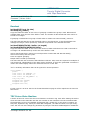
C++ Code Example
25ps mode
#include
#include
#include
#include
"tdcmanager.h"
<string>
<list>
<fstream>
int main(int argc, char* argv[])
{
TDCManager manager(0x1A13, 0x0001);
try {
manager.Init();
manager.ReadConfigFile("myexperiment.cfg");
manager.Start();
} catch (TDCConfigException& e) {
return -1;
}
int amountToRead = 1000000;
HIT buffer[2000];
ofstream of("test.dat", ios::out | ios::binary);
}
while(amountToRead > 0)
{
int count = manager.Read(buffer,2000);
for(int i = 0; i < count && i < amountToRead; i++) {
of.write((const char*)(buffer +i), sizeof(HIT));
}
amountToRead -= count;
}
manager.Stop();
manager.CleanUp();
return 0;
cronologic GmbH & Co. KG
23
HPTDC8-PCI
Time to Digital Converter
with 25ps Resolution
Rev 3.6.0 as of 2015-11-26
Firmware 7, Driver v3.6.0
User Manual
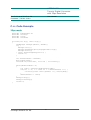
C# Code Example
1ps mode
using
using
using
using
using
using
cronologic;
System.IO;
System;
System.Collections.Generic;
System.Linq;
System.Text;
namespace application {
class Program {
static void Main(string[] args)
{
HPTDCManager manager = new HPTDCManager();
try {
manager.Init();
manager.ReadConfigFile("myexperiment.cfg");
manager.Start();
} catch (HPTDCException e) {
System.Console.WriteLine(e.Message);
return;
}
int amountToRead = 1000000;
HPTDCHit[] buffer = new HPTDCHit[2000];
StreamWriter newFile = new StreamWriter("myexperiment.csv");
while(amountToRead > 0)
{
int count = manager.ReadHPTDCHit(buffer);
for(int i = 0; i < count && i < amountToRead; i++) {
newFile.Write(buffer[i].channel + ", ");
newFile.Write(buffer[i].type + ", ");
newFile.WriteLine(buffer[i].time);
}
amountToRead -= count;
}
newFile.Close();
manager.Stop();
manager.CleanUp();
}
}
}
cronologic GmbH & Co. KG
24
HPTDC8-PCI
Time to Digital Converter
with 25ps Resolution
Rev 3.6.0 as of 2015-11-26
Firmware 7, Driver v3.6.0
User Manual
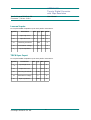
Lowres Connector Pinout
Signal
Pin Number
Signal
3.3V
1
2
reserved
GND
3
4
reserved
GND
5
6
CH11
GND
7
8
CH12
GND
9
10
CH13
GND
11
12
CH14
2.5V
13
14
CH15
GND
15
16
CH16
GND
17
18
CH17
GND
19
20
CH18
GND
21
22
CH19
GND
23
24
CH20
5V
25
26
not connected
HPTDC-MDS lowres connector pinout
cronologic GmbH & Co. KG
25
HPTDC8-PCI
Time to Digital Converter
with 25ps Resolution
Rev 3.6.0 as of 2015-11-26
Firmware 7, Driver v3.6.0
User Manual
Electrical Characteristics
Environmental Conditions
The inboard is designed to be operated under the following conditions.
Symbol
Parameter
Min
Typ
Max Units
T
Ambient Temperature
5
50
°C
RH
relative humidity at 31°C
30
70
%
Power Supply
Symbol
Parameter
I
PCI 5V rail power consumption
VCC
PCI 5V rail power supply
Min
4.75
other PCI power supply rails
Typ
5
Max Units
2.5
A
5.25
V
not connected
Hi-Res Inputs
AC coupled NIM compatible inputs with parallel termination.
The idle level is high, signals are given by negative pulses.
Symbol
Parameter
Min
VDC
DC input voltage
-10
10
V
ΔVIL
AC Pulse low level (relative to DC level)
-1.5
-0.5
V
ΔVTH
Typ
Max Units
AC switching threshold (relative to DC level) -0.34 -0.24 -0.14
V
VT
termination voltage
0
V
Z
input impedance
50
Ω
tpw
pulse width
tdead
dead time after edge
cronologic GmbH & Co. KG
5
5
26
3000
ns
10
ns
HPTDC8-PCI
Time to Digital Converter
with 25ps Resolution
Rev 3.6.0 as of 2015-11-26
Firmware 7, Driver v3.6.0
User Manual
Trigger Input
AC coupled NIM compatible input with parallel termination.
The idle level is high, signals are given by negative pulses.
Symbol
Parameter
Min
Typ
Max Units
VTDC
DC input voltage
-10
10
V
ΔVTIL
AC pulse low level (relative to DC level)
-1.5
-0.5
V
ΔVTTH
AC Switching threshold (relative to DC level)
-0.38
V
ZT
input impedance
50
Ω
VTT
termination voltage
0
V
tTpw
pulse width
30
tTdead
pulse seperation
30
3000
Clock Input
AC coupled input with 50Ω thievenin termination after the capacitor.
Symbol
Parameter
Min
VCH
input common mode voltage
-4
7
V
VCIL
input amplitude peak-to-peak
0.8
3.3
V
ZC
input impedance
50
Ω
tC
clock period
12.5 12.81 13.1
ns
duty cycle
45
Typ
50
Max Units
55
%
1 Deviation from the nominal period will scale measurement results.
cronologic GmbH & Co. KG
27
ns
HPTDC8-PCI
Time to Digital Converter
with 25ps Resolution
Rev 3.6.0 as of 2015-11-26
Firmware 7, Driver v3.6.0
User Manual
Lowres Inputs
DC coupled CMOS compatible inputs with parallel termination.
Symbol
Parameter
Min Typ Max Units
VLIH
input high level
2
3.3
V
VLIL
input low level
0
0.8
V
VLTH
switching threshold
1.65
V
VLT
termination voltage
0
V
VL
input impedance
100
Ω
TDC8 Sync Input
DC coupled CMOS compatible inputs with parallel termination.
Symbol
Parameter
Min
VSIH
input high level
2
3.3
V
VSIL
Input low level
0
0.8
V
VSTH
switching threshold
1.65
V
VST
termination voltage
0
V
ZS
input impedance
1000
Ω
cronologic GmbH & Co. KG
Typ
Max Units
28
HPTDC8-PCI
Time to Digital Converter
with 25ps Resolution
Rev 3.6.0 as of 2015-11-26
Firmware 7, Driver v3.6.0
User Manual
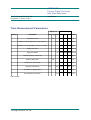
Time Measurement Parameters
up to 7.x
Symbol
Parameter
8.x and up
Min Typ Max Min Typ Max Units
nominal bin size
25
stability over temperature (0°C to 85°C)
25
ps
20
ppm
stability over temperature (-20°C to 70°C)
1
ppm
aging first year
5
1
ppm/a
aging thereafter
2
1
ppm/a
4
ppm
initial frequency inaccuracy
peak to peak jitter
25
ps
differential nonlinearity
-25
25
-25
25
ps
integral nonlinearity
-25
25
-25
25
ps
crosstalk (7 aggressors)1
150
150
ps
skew between channels1
2.4
2.4
ns
1)Not tested.
cronologic GmbH & Co. KG
29
HPTDC8-PCI
Time to Digital Converter
with 25ps Resolution
Rev 3.6.0 as of 2015-11-26
Firmware 7, Driver v3.6.0
User Manual
Data Rate
In order to guarantee that absolutely no hits are lost during data acquisition, the following hit
counts must not be exceeded. In many cases exceeding these values will result only in a small
amount of lost hits depending on the pattern of the arriving hits.
Symbol
Scope
Number of
Hits
Timeframe
Hcrit1
highres channel1
1
10ns
Hcrit2a
highres channel1,4
(25ps resolution)
2
400ns
Hcrit2b
highres channel1,4
(100ps resolution)
2
100ns
Hcrit3a
highres channel1,5
(25ps resolution)
4
400ns
Hcrit3b
highres channel1,5
(100ps resolution)
4
100ns
Hcrit4
highres channel pair2
256
25us
Hcrit4
all highres channels2
512
8us
Lcrit1
lowres channel1
1
30ns
Lcrit2
lowres channel1
16
800ns
Lcrit3
all channels3
2000
500us
1) Hits lost as these constraints are not met cannot be detected by hardware.
2) Hits lost due to these constraints are reported as errors in the datastream. The exact number of lost hits cannot be detected.
3) Hits lost due to these constraints are reported with the exact number of lost hits. The number of lost hits is reported separately for trigger channels.
4) This criterion applies when rising edge is enabled for at least one hires channel and falling
edge is enable for at least one hires channel. This might be the same or a different channel. Up to driver version 3.0.0 inclusive this rule included lores channels.
5) This relaxed criterion applies when no hires channels uses rising edges or no hires channels
uses falling edges. Up to driver version 3.0.0 inclusive this rule included lores channels.
cronologic GmbH & Co. KG
30
HPTDC8-PCI
Time to Digital Converter
with 25ps Resolution
Rev 3.6.0 as of 2015-11-26
Firmware 7, Driver v3.6.0
User Manual
System Integration
The devices are not ready to use as delivered by cronologic. It requires the development of specialized software to fulfill the application of the end user. The device is provided to system integrators
to be built into measurement systems that are distributed to end users. These systems usually
consist of a the HPTDC, a main board, a case, application software and possible additional electronics to attach the system to some type of detector. They might also be integrated with the detector.
The HPTDC8-PCI and HPTDC-MDS are designed to comply with DIN EN 61326-1 when operated on
a PCI compliant main board housed in a properly shielded enclosure. When operated in a closed
standard compliant PC enclosure the device does not pose any hazards as defined by EN 61010-1.
Radiated emissions, noise immunity and safety highly depend on the quality of the enclosure. It is
the responsibility of the system integrator to ensure that the assembled system is compliant to
applicable standards of the country that the system is operated in, especially with regards to user
safety and electromagnetic interference. Compliance was only tested for attached cables shorter
than 3m.
The HPTDC contains up to 1g of lead. It is the responsibility of the system integrator to check
whether the resulting system will comply to or is exempt from ROHS regulations such as EU directive 2002/95/EG.
Recycling
Cronologic is registered with the „Stiftung Elektro-Altgeräte Register“ as a manufacturer of electronic systems with Registration ID DE 77895909.
The HPTC belongs to category 9,” Überwachungs und Kontrollinstrumente für ausschließlich
gewerblich Nutzung”. The last owner of a HPTDC must recycle or treat the board in compliance with
§11 and §12 of the german ElektroG or return it to cronologic:
cronologic GmbH & Co. KG
Jahnstraße 49
D-60318 Frankfurt
Contact and Updates
Driver updates can be downloaded from the HPTDC product page at:
http://www.cronologic.de/
For technical questions please send an E-Mail to
[email protected]
cronologic GmbH & Co. KG
31