1
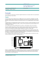
HPTDC8-PCI
Time to Digital Converter
with 25ps Resolution
Rev 3.6.0 as of 2015-11-26
Firmware 7, Driver v3.6.0
User Manual
Multiple boards
Unique channel numbers are assigned to each board. The second board will usually start with channel number 21, and the third one with channel number 42. A serial number of the type X.Y is printed on every TDC card (see Figure 4). X denotes the year of production minus 2000, Y is an integer
greater than zero. The card with the lowest number is initialized as the first board, the one with the
next higher number as the second, and the board with the highest number is the third board. For
example: three cards with the numbers 6.7, 7.11 and 6.12 are installed. The first card (with channel numbers 0 to 20) is the one with number 6.7, the second card (channels 21 to 41) is the one
with serial number 6.12 and the third card (channels 42 to 62) is card 7.11.
Figure 4: The card's serial number located on the PCI-interface chip. The first digit denotes the
year of production, the second is a serial number that is unique within that year.
Multiple boards with external clock reference
This is the preferred mode of operation when using multiple boards: a common clock signal is connected to the clock input of each board. This signal must have a frequency of 78.125MHz.
In this case all acquisition modes described above are supported and the additional measurement
error described above is avoided.
Using an external clock, a trigger signal needs to be connected to one TDC board only. This must
be the first board (channels 0 to 20).
In order to enable the external clock source the configuration parameter ExternalClock needs to
be set to true.
The resolution is reported as 25.00000 ps when external clocking is selected, relying on the external clock having the correct frequency.
cronologic GmbH & Co. KG
13