1
US 6,976,052 B2
1
2
SPA CONTROL SYSTEM
ef?ciently controls the operation of the spa and is not
adversely affected by the corrosive environment surround
ing the spa. The spa temperature control system generally
comprises a heating element, a sensor for detecting the
temperature of the Water, and a microcomputer for process
This application is a continuation of US. patent appli
cation Ser. No. 08/822,179 ?led Mar. 20, 1997, now US.
Pat. No. 6,253,227, Which is a continuation of US. appli
cation Ser. No. 08/703,177 ?led Aug. 23, 1996, noW
abandoned, Which is a continuation of US. application Ser.
No. 08/327,927 ?led Oct. 24, 1994, now US. Pat. No.
5,559,720, Which is a continuation of US. patent application
Ser. No. 08/225,282 ?led Jan. 11, 1994, now US. Pat. No.
5,361,215, Which is a continuation of US. patent application
Ser. No. 07/224,869 ?led Jul. 26, 1988, noW abandoned,
Which is a continuation-in-part of US. patent application
Ser. No. 07/054,581, ?led May 27, 1987, noW abandoned,
each of the above related applications and patents being
ing signals generated by said sensor and for activating and
deactivating the heating element. In one embodiment of the
invention, the microcomputer assesses the time necessary to
heat Water from an initial temperature to a selected tem
10
can be calculated. The heating rate can be stored by the
microcomputer and can be used to determine the star time
necessary to heat the spa Water from an initial temperature
to a selected temperature by a desired time. In the same or
15
incorporated herein by reference.
monitored to detect problems in the system.
BRIEF DESCRIPTION OF THE DRAWINGS
20
FIG. 1 illustrates a schematic block draWing of the spa
control system.
FIG. 2 illustrates a block diagram of the microcomputer
and its associated components.
control panel to effectively control various operating func
tions of the spa.
BACKGROUND OF THE INVENTION
another embodiment of the invention, the temperature dif
ference betWeen tWo sensors in the spa system can be
FIELD OF THE INVENTION
This invention relates to the development of a spa control
system. More particularly, this invention relates to a spa
control system Which uses an interconnection panel and a
perature. From this information, the heating rate of the Water
25
FIG. 3 illustrates a block diagram of the spa control
The design of systems to control spas is complicated by
the environment of the spa. Typically, spa control systems
system ?eld interconnection panel.
contain heating elements, controls, sWitches, and Wiring
softWare Which operates the spa control system through the
harnesses Which deteriorate When eXposed to moisture or
eXtreme levels of humidity and a hostile chemical environ
ment. Since the chemically treated, heated Water of the spa
FIG. 4 illustrates a functional block diagram of the
microcomputer.
30
raises the humidity level and produces corrosive gases, the
atmosphere surrounding the controls of the spa unit is
FIG. 6 illustrates the overall softWare control of the spa
control system.
inherently corrosive to spa control systems.
The accuracy of the temperature of the spa Water is
essential to the safety and comfort of the spa user. This
35
temperature is dif?cult to accurately control, since the tem
perature of the Water can vary rapidly depending on the
number of spa users, the ambient temperature of the air, and
other environmental factors. To conserve energy, the spa
40
temperature is customarily raised to the desired level shortly
FIGS. 7—13 illustrate ?oWcharts of various softWare func
tions of the spa control system.
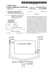
FIG. 14 illustrates diagrammatically a system constructed
in accordance With the preferred embodiment.
DESCRIPTION OF THE PREFERRED
EMBODIMENTS
FIGS. 1 and 2 illustrate a block diagram of the overall spa
control system. The spa control system uses an intelligent
before the eXpected use of the spa, and is not maintained at
a constant temperature When the spa is unattended. Depend
ing on the use of the spa, the temperature of the spa Water
may be cycled several times per day. During these cycles,
FIG. 5 illustrates one embodiment of a display panel for
the operation of the spa control system.
microcomputer 10 to monitor and control the operation of
45
the spa. The system uses solid state electronic components
Which eliminate many of the problems associated With
traditional mechanical timer and relay control systems. The
the control of the Water temperature is dif?cult to maintain
Without overheating or underheating the Water. Typically, a
spa control system merely heats the Water With a heating
element until the temperature of the Water matches a pre
determined setting selected by the spa user. Since the heating
element is not turned off until that desired Water temperature
is reached, the residual heat in the heating element may
increase the temperature of the Water beyond the actual
temperature desired. Conversely, the location of the tem
use of solid state electronic components increases the reli
ability of the system and reduces the maintenance necessary
to maintain the spa in operable condition.
Referring to FIGS. 1 and 14, the external system generally
comprises a spa control panel 12 Which is connected to a
system interconnection panel 14. The system interconnec
tion panel 14 is also connected to poWer input 16, to various
perature sensor may be located in the spa in such a fashion 55 sensors Which detect parameters such as How rate 18,
temperature 20, 21 and pH 22 of the Water, and also the
that it does not sense the actual, median Water temperature.
mechanical and electrical components of the spa, such as the
Accordingly, the heating element may be turned off before
pump 24, heater 26, bloWer 28, and lights 30. The heater 26
the temperature of the Water reaches the desired level.
Present spa controllers operate on line voltages Which can
present a safety haZard to the spa users. To meet desired
may be interlocked to the pump 24 so that the pump 24 is
60
safety speci?cations, these controls are typically located
aWay from the sap, hoWever, this separation is inconvenient
continuously pumping Water over the heating element 29 of
the heater 26 While the heater 26 is activated. This prevents
a “hot spot” from developing in the spa system Which could
damage the components of the spa or give erroneous mea
to the spa user.
surements.
SUMMARY OF THE INVENTION
The present invention overcomes the foregoing difficul
ties by providing a spa control system Which accurately and
65
The system is a microcomputer-based system. In addition
to the microcomputer 10, the system utiliZes several other
devices. While the control program runs on the microcom