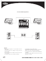
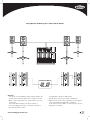
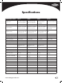
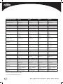
1
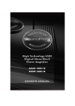
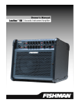
OWNER’S
MANUAL
> HP112 Powered
Loudspeaker
TWO
"
12 WAY
500W 129dB
Bi-Amped Peak SPL
> HP115 Powered
Loudspeaker
TWO
"
15 WAY
500W 131dB
Bi-Amped Peak SPL
> HP215 Powered
Loudspeaker
DUAL
TWO
"
15 WAY
850W 134dB
Bi-Amped Peak SPL
> HP118S Powered
Subwoofer
18"SUB
700W 129dB
Powered Peak SPL
Contents
Important Safety information
System Features
HP Model Descriptions
HP Rear Panel Controls & Operation
Set-up Diagrams
Specifications
Cables and Connectors
Warranty
1
3
4
5-8
9-14
15
17
18
Welcome
CONGRATULATIONS ON YOUR PURCHASE OF A
HARBINGER HP HIGH POWER SERIES LOUDSPEAKER.
Please review all the information provided in this manual to ensure
that you attain the best possible sound quality from your system.
Harbinger HP Series powered loudspeakers provide outstanding
clarity and sound power for a variety of applications. HP Series
speakers are the perfect choice for any portable PA applications
requiring reliable sound power for live performance, presentation
or playback for bands, DJ’s, presenters, schools, and Houses
of Worship.
Harbinger HP112, HP115, HP215 full range powered
loudspeakers may be used as stand-alone main speakers, or
combined with the HP118S subwoofer to form larger systems. All
4
HP Series loudspeakers feature simple rear panel controls, with
line level outputs for linking multiple speakers. Please see the setup diagrams at the end of this manual for examples of possible
system configurations.
Harbinger HP series powered loudspeakers were designed
using advanced acoustic and audio techniques with premium
components, comprehensive protection circuitry, and robust
construction to provide years of consistent, reliable performance.
Key features include: Bi-Amp power modules with high efficiency
Class G low frequency amplification with high current output stage
and custom signal processing; clip/limit, thermal, and short circuit
protection; optimized acoustic designs using PETP film compression
driver diaphragms; heat vented low frequency drivers; and sturdy
birch plywood.
Owner’s Manual for models HP112 • HP115 • HP215 • HP118S
Important Safety Instructions
Please keep this instruction manual for future reference and for the
duration of owning the HP powered loudspeaker. Please carefully
read and understand the instructions inside this owner’s manual before
attempting to operate your new powered loudspeaker.
10. P OWER SOURCES – This product should be operated only from the
type of power source indicated on the rating label. If you are not
sure of the type of power supply to your home, consult your product
dealer or local power company.
This instruction manual includes essential safety information regarding
the use and maintenance of the amplifier. Take special care to heed all
warning symbols and signs inside this manual and those printed on the
amplifier on the back of the loudspeaker.
11. G
ROUNDING OR POLARIZATION – Do not defeat the safety
purpose of the polarization or grounding-type plug. The wide blade
or the third prong is provided for your safety. If the provided plug
does not fit your outlet, consult an electrician for replacement of the
obsolete outlet. Do not defeat the safety purpose of the grounding
prong.
WARNING
TO PREVENT FIRE OR SHOCK HAZARD, DO NOT EXPOSE THE
AMPLIFIER TO WATER/MOISTURE, NOR SHOULD YOU OPERATE THE
AMPLIFIER NEAR ANY WATER SOURCE.
The exclamation point triangular symbol is intended to alert the user to the
presence of important operating and maintenance(servicing) instructions
in the user manual accompanying the Amplifier.
The lightning flash with an arrow triangular symbol is intended to alert
the user to the presence of non-insulated “dangerous voltage” within the
product’s enclosure, and may be of sufficient magnitude to constitute a
risk of electric shock
WARNING
Handle the power supply cord with care.
Do not damage or deform it as it may cause electric shock or malfunction
when used. Hold the plug attachment when removing from wall outlet. Do
not pull on the power cord.
IMPORTANT SAFETY PRECAUTIONS
12. P OWER-CORD PROTECTION – Power-supply cords should be
routed so that they are not likely to be walked on or pinched by
items placed upon or against them, paying particular attention to the
cord in correspondence of plugs, convenience receptacles, and the
point where they exit from the amplifier.
13. Cleaning – The speaker and amplifier should be cleaned only
as recommended by the manufacturer. Clean by wiping with a dry
cloth. Avoid getting water inside the speaker or amplifier.
14. N
on-use Periods – The power cord of the amplifier should be
unplugged from the outlet when left unused for a long period of
time.
15. O
BJECT AND LIQUID ENTRY – Care should be taken so that objects
do not fall and liquids are not spilled into the enclosure through
openings.
16. D
AMAGE REQUIRING SERVICE – The amplifier should be serviced
by qualified service personnel when:
A. The power-supply cord or the plug has been damaged; or
B. O
bjects have fallen, or liquid has been spilled into the
amplifier; or
C. T he amplifier has been exposed to rain; or
3. H
EED WARNINGS – All warnings on the amplifier and in the
operating instructions should be adhered to.
D. T he amplifier does not appear to operate normally or
exhibits a marked change in performance; or
4. F ollow Instructions – All operating and use instructions should
be followed.
E. T he amplifier has been dropped, or the enclosure
damaged.
5. D
O NOT turn on the HP amplifier module before connecting all other
external devices.
17. K
eep the speaker system out of extended or intense direct sun light.
1. R
EAD INSTRUCTIONS – All the safety and operating instructions
should be read before this product is operated.
2. R
ETAIN INSTRUCTIONS – The safety and operating instructions
should be retained for future reference.
6. W
ater and Moisture – Moisture can damage the HP amplifier
module and can cause corrosion of electrical contacts. The speaker
system should not be used near water - for example, a bathtub,
washbowl, kitchen sink, laundry tub, wet basement, or near a
swimming pool, and the like.
7. C
arts and Stands – The speaker system should be used only with a
cart or stand that is recommended by the manufacturer. A speaker and
cart combination should be moved with care. Quick stops, excessive
force, and uneven surfaces may cause the speaker and cart combination
to overturn.
8. W
ALL OR CEILING MOUNTING – The product should never be
mounted to a wall or ceiling.
9. H
EAT – The amplifier on the back of the HP loudspeaker should be
situated away from heat sources such as radiators, heat registers,
stoves, or other sources (including amplifiers) that produce heat.
www.harbingerproaudio.com
18. N
o containers filled with any type of liquid should be placed on or
near the speaker system.
19. S
ERVICING – The user should not attempt any service to the speaker
and/or amplifier beyond that described in the operating instructions.
All other servicing should be referred to qualified service personnel.
20. V
ENTILATION – Slots and openings in the amplifier are provided
for ventilation and to ensure reliable operation of the product and
to protect it from overheating. These openings must not be blocked
or covered. The openings should never be blocked by placing the
product on a bed, sofa, rug, or other similar surface. This product
should not be placed in a built-in installation such as a bookcase
or rack.
21. A
TTACHMENTS – do not use attachments not recommended by the
product manufacturer, as they may cause hazards.
1
22. A
CCESSORIES – Do not place this product on an unstable cart,
stand, tripod, bracket, or table. The product may fall, causing serious
injury to a child or adult, and serious damage to the product. Use
only with a cart, stand, tripod, bracket, or table recommended by the
manufacturer, or sold with the product.
23. L IGHTNING – For added protection during a lightning storm, or
when it is left unattended and unused for long periods of time, unplug
it from the wall outlet. This will prevent damage to the product due to
lightning and power-line surges.
24. R
EPLACEMENT PARTS – When replacement parts are required, be
sure the service technician has used replacement parts specified by
the manufacturer or have the same characteristics as the original
part. Unauthorized substitutions may result in fire, electric shock, or
other hazards.
25. S
AFETY CHECK – Upon completion of any service or repairs to
this product, ask the service technician to perform safety checks to
determine that the product is in proper operating condition.
26. F USES – Always use the correct rating and type of fuse as indicated
on the rear panel of the amplifier. Note the proper rating fuse is
determined by the AC line voltage in the country this speaker system
is being operated. COMPLETELY DISCONNECT POWER CORD
FROM AMPLIFIER BEFORE ATTEMPTING TO REPLACE FUSE!
27. A
C SELECT SWITCH: This switch must be set to match the AC line
voltage in the country this speaker system is being operated. To
change the setting, loosen (do not remove) the two screws above
and below the slide switch. Temporarily move the protective cover
strip and slide the actuator to match the voltage in your country.
Place the protective cover strip back over the switch and tighten the
two screws. COMPLETELY DISCONNECT POWER CORD FROM
AMPLIFIER BEFORE ATTEMPTING TO CHANGE AC VOLTAGE
SETTINGS!
28. H
arbinger HP Series powred loudspeakers are not designed for
temporary or permanent suspension. Any attempt to suspend an HP
series cabinet could result in injury or death.
HEARING DAMAGE AND PROLONGED EXPOSURE TO
EXCESSIVE SPLs
Harbinger HP Series powered loudspeakers are capable of producing
extremely loud volume levels that can cause permanent hearing damage
to performers, production crews or the audience. Hearing protection is
recommended during long-term exposure to high SPLs (sound pressure
levels).
Remember, if it hurts, it is definitely too loud! Long term exposure
to high SPLs first causes temporary threshold shifts; limiting your
ability to hear the actual loudness and exercise good judgment.
Repeated long term exposure to high SPLs will cause permanent
hearing loss.
Please note the recommended exposure limits in the accompanying table.
More information about these limits is available on the US government
Occupational Safety and Health (OSHA) website at: www.osha.gov
Permissible Noise Exposures (1)
Duration per day, hours
Sound level dBA
slow response
8
6
4
3
2
1.5
1
0.5
0.25 or less
90
92
95
97
100
102
105
110
115
To prevent electric shock, do not use a polarized plug with an extension
cord, receptacle or other outlet unless the blades can be fully inserted to
prevent blade exposure.
RISK OF
RISQUE DE CHOC
RISK OF
DE CHOC
ELECTRIC
SHOCK RISQUE
ELECTRIQUE
NE
ELECTRIC
SHOCK ELECTRIQUE
DO NOT OPEN
PAS OUVRIRNE
DO NOT OPEN
PAS OUVRIR
RISK OF
RISQUE DE CHOC
ELECTRIC SHOCK ELECTRIQUE NE
CAUTION: To reduce the risk of electric shock,
not
DO NOTdo
OPEN
PAS OUVRIR
CAUTION: To reduce the risk of electric shock, do not
remove chassis. No user-serviceable parts inside.
remove chassis. No user-serviceable parts inside.
Refer servicing to qualifiedCAUTION:
service personnel.
To reduce the risk of electric shock, do not
Refer servicing to qualified service personnel.
remove
No user-serviceable
parts inside.
AVERTISEEMENT: Pour réduire leschassis.
risques d’incendie
et
AVERTISEEMENT: Pour réduire
risques d’incendie et
Referles
servicing
d’électrocution, ne pas exposer
ce
matérialtoà qualified
la pluie ouservice personnel.
d’électrocution, ne pas exposer ce matérial à la pluie ou
à l’humidité.
AVERTISEEMENT: Pour réduire les risques d’incendie et
à l’humidité.
d’électrocution, ne pas exposer ce matérial à la pluie ou
à l’humidité.
THIS SYMBOL IS INTENDED TO ALERT THE USER TO THE PRESENCE
OF IMPORTANT OPERATING AND MAINTENANCE (SERVICING)
INSTRUCTIONS IN THE LITERATURE ACCOMPANYING THE UNIT.
APPARATUS SHALL NOT BE EXPOSED TO DRIPPING OR SPLASHING
AND THAT NO OBJECTS FILLED WITH LIQUIDS, SUCH AS VASES,
SHALL BE PLACED ON THE APPARATUS.
2
Owner’s Manual for models HP112 • HP115 • HP215 • HP118S
System Features
AMPLIFIER FEATURES
•B
i-amp design with discrete output stages for both the woofer
and compression driver
•H
igh efficiency Class G low frequency amplification with custom
signal processing
• P roprietary 4th order electronic X-over and multi-stage custom
equalization on full range models.
• T hird order electronic crossover on HP118S
powered subwoofer
•B
uilt-in compressor/limiter
•S
ubsonic filter: 12dB/octave
• F ull thermal & short circuit protection
•1
00Hz 18dB/octave low cut switch on Full Range models
• P olarity switch (HP118S Subwoofer)
•B
alanced XLR input (Left and Right on HP118S Subwoofer)
• L eft and Right Balanced XLR full-range outputs on HP118S
Subwoofer
• A matched wave front phase corrector produces a coherent
sound wave at the horn throat, yielding detailed and dynamic
mid and high frequency response
COMPONENTS
Compression Driver:
• 1”exit with Celestion PETP film diaphragm
Horns:
• 90° x 40° constant directivity horn (HP115 and HP215)
• 75° conical wave guide (HP112)
LF Transducers:
• Vented magnet assemblies for advanced cooling
• High temperature copper voice coil wound on polyamide
former for increased reliability
• Celestion SP-1200 (HP112)
• Celestion SP-1500 (HP115, HP215))
• Proprietary SP-1804 cast frame subwoofer (HP118S)
• L eft and Right balanced XLR high-pass outputs on HP118S
Subwoofer
CABINET FEATURES
•G
round lift switch
• Made in U.S.A.
• L arge heatsink with convection cooling
• 5/8” birch plywood construction (HP112, HP115, HP215)
•O
versized toroidal transformer
• 3/4” birch plywood construction (HP118S)
• L EDs for Power, Protect, Limit and Signal
• Main & monitor sitting positions (HP112)
•1
15V/230V 60Hz/50Hz selector switch
• Reinforced internal bracings
PETP-FILM DIAPHRAGM COMPRESSION DRIVER
•O
ptimized acoustic and magnetic design achieves outstanding
clarity and reliability
• Environmentally friendly Warnex® scratch resistant black
paint finish
• 16-gauge, wrap-around steel grilles
• Metal handles, and rubber feet rubber strips (HP112)
•A
one-piece, PETP film diaphragm and surround optimizes
energy transfer for greater efficiency
• Metal pole mounting cup (HP118S)
• P atented clamping system yields low distortion performance
while improving the mid-band response
• Front logo illuminated with blue LED
• Stand mount on HP112, HP115
• P olyimide-insulated, copper-clad aluminium voice coil is edgewound on a glass-fiber former producing lower distortion and
superior power-to-weight ratio
www.harbingerproaudio.com
3
HP Model Descriptions
HP112: The HP112 was designed to operate on the floor as a
stage monitor, to be pole mounted on a 1 1/2" diameter speaker
stand or elevated on top of the HP118S subwoofer using a pole
inserted into the pole cup of the HP118S. Do not exceed a pole
length longer than 31" (787mm) when supported atop an HP118S
subwoofer.
HP215: The HP215 was designed to operate sitting on the
floor, stage, or on top of the HP118S subwoofer enclosure. Do
not attempt to pole mount this loudspeaker atop the HP118S
subwoofer cabinet!
HP115: The HP115 was designed to operate on the floor, stage,
subwoofer enclosure, or pole mounted on a 1 1/2" diameter
loudspeaker support pole. The pole can be part of a loudspeaker
stand or a pole inserted into the pole cup of the HP118S. When
used in conjunction with the HP118S, the mounting pole length
must not exceed 26” (660mm) in length.
HP118S: The HP118S was designed to operate sitting on the
floor or on the stage. A pole cup, on the top of the enclosure,
accepts 1 3/8" loudspeaker mounting poles. For best quality
sound, detach the supplied casters while the subwoofer is being
played. Do not pole mount or stack more than one Full-range HP
enclosure on top of the HP118S.
4
Owner’s Manual for models HP112 • HP115 • HP215 • HP118S
HP Rear Controls & Operation
HP118S
HP112, HP115 & HP215
1
1
2
2
3
3
4
4
5
5
6
7
7
8
10
8
9
10
11
12
11
2-WAY 500-WATT
POWERED LOUDSPEAKER
12
BI-AMP DESIGN
INTEGRATED SIGNAL
PROCESSING
13
www.harbingerproaudio.com
13
5
POWER Indicator
1 LED
The
green LED POWER indicator, located on the back of the
amplifier, will illuminate when the AC Power switch is in the “ON”
position. The LED POWER indicator will dim and turn off when the
AC Power switch is in the “off” position or AC mains power has
been disconnected from the loudspeaker.
If the POWER indicator does not illuminate when the loudspeaker
is powered on, verify the AC mains line cord is properly connected
to the loudspeaker and inserted into the AC outlet. Verify the AC
outlet at the venue of operation is functioning properly. In the event
of the AC mains outlet functioning properly, but the loudspeaker
fails to operate, the loudspeaker may require servicing. Please
contact [email protected] for service instructions.
LED INDICATOR
2 PROTECT
If the power module overheats, the amplifier will go into
“protection mode” to limit further temperature rise. The amplifier
will take about 30 seconds to several minutes for the temperature
to drop and resume operation. When this occurs, the exposed
heat sink will feel hot to the touch.
•Overheating
is usually caused by excessive ambient
temperature, direct sunlight for a prolonged period of
time during operation, or playing the loudspeaker past its
operational limits.
If thermal overheating occurs, reduce signal level to avoid constant
illumination of the LIMIT LED INDICATOR. In some circumstances,
for example when ambient temperature is too high, you may need
to set a fan behind the speaker to improve ventilation at heatsink.
LED INDICATOR
3 LIMIT
The
red LIMIT indicator alerts the user that the amplifier output
signal is clipping and therefore is being compressed by the built-in
clip-limiter.
Momentary
Bright Red Flashes
•Indicates
that the amplifier is clipping briefly causing overdrive
distortion and the internal limiter is reducing gain.
•HP
amplifiers employ a sophisticated compressor-limiter
circuitry, which is nearly inaudible at moderate overdrive
conditions. It is normal to see the occasional flashing of the
red LIMIT LED.
Continuous
Bright Red Light
•Indicates
continuous and gross overloading of the amplifier.
Such overloads are audible and may lead to overheating of the
amplifier and shortening the life of the speaker components.
If the amplifier is grossly overloaded and the red LIMIT LED is
on the most of the time, the operator should reduce the signal
level so that LIMIT LED only flashes occasionally.
6
LED INDICATOR
4 SIGNAL
The
green SIGNAL indicator alerts the operator to the presence of
an input signal at the loudspeaker amplifier.
•
If there is no indication, check the gain settings on the amplifier
and increase the gain if necessary. Check input connections
and audio source for signal. If no output persists, try a different
signal cable from your mixer to the HP Series loudspeaker.
•I
f the green SIGNAL LED remains illuminated without a source
connected, the amp may need servicing.
Control
5 LEVEL
Turn
the LEVEL control clockwise to increase gain and counter
clockwise to decrease gain. When operating with the GAIN
set at 1/3 volume or below, it may be possible to exceed the
headroom of input circuitry on your loudspeaker. If this is the
case, reduce the input signal strength and increase the gain of the
loudspeaker amplifier.
Always
observe the red LIMIT LED on the amplifier panel. This
LED lights when a signal is clipping and the compressor-limiter
is activated. All HP Series amplifiers employ a sophisticated
limiter circuitry, which monitors signal condition at both LF and HF
amplifiers (LF only on HP118S) and compresses the output signal
when necessary to protect woofer and compression driver from
damages. Limiter circuitry works very unobtrusively; you may not
even notice when it activates. It may prompt you to push input
signal more, but it is a good practice to have red LIMIT LEDs
blink occasionally and not constantly. A constant LIMIT LED light
indicates a gross overloading condition and should be avoided.
Reduce the signal level if the LIMIT LED lights or blinks constantly.
NOTE
that LEVEL Control has a range of 30dB. It does not
attenuate output signal to zero. LEVEL control on the loudspeakers
is used to set optimal maximum level for performance, not for
constant control of sound volume. Your mixer’s master volume
control should be used for this purpose.
NOTE
that LEVEL control provides about 12dB attenuation in
middle position. You will find that in most cases the best sound
(lowest distortions and lowest noise) will be achieved when LEVEL
control is set somewhere between middle and full clockwise
position.
Cut Switch
6 Low
HP112,
HP115, HP215: Found beneath the LEVEL control, this small
slider switch engages or disengages the 100Hz 18db/Octave
Low Cut filter. Switch the filter OFF when not using subwoofers or
other low frequency enclosures. Switch the filter ON when you
are connecting subwoofers or low frequency systems. This will
enable your subwoofer-equipped system to operate properly and
Owner’s Manual for models HP112 • HP115 • HP215 • HP118S
allow the Full-range loudspeakers to provide improved clarity in
the mid and high-range frequencies.
DO
NOT engage the LOW-CUT switch on HP112, HP115, or
HP215 Full-range loudspeakers when connected to HP outputs of
HP118S subwoofer. The Input signal for your full-range loudspeaker
has already been processed by HP118S’s circuitry.
Connections
8 Input
All
Full-range models have one female XLR line-level input
marked INPUT.
The
HP118S has a second connector (two input connectors
total), one for the left channel’s audio input and one for the right
channel’s audio input.
HP112:
We recommend switching the filter ON for the best sound
clarity. If using as a floor monitor, turn the filter ON for improved
vocal range clarity and to reduce low frequency build-up
on stage.
Balanced
connections should be used as much as possible to
reduce AC hum and interference, especially with long runs of
cable. On all HP amplifier modules, the input impedance is 20k
Ohm for balanced connections.
Connections
7 Output
All
Full-range models have one XLR output connector marked
OUTPUT. The output connector is wired in parallel with the input,
allowing connection of multiple enclosures in a “daisy-chain”
fashion. The HP118Shas two sets of output connectors, one set
(left and right) for full-range outputs (wired in parallel with inputs)
and one set (left and right) for high-pass outputs.
HP112,
HP115, HP215: Insert the male XLR connector into the jack
marked INPUT. Ensure the connector is fully seated.
HP118S:
FOR STEREO OPERATION WITH FULL-RANGE
CABINETS: From your mixer, insert the left channel’s XLR
connector into the left channel’s (L) INPUT connector. Connect
the right channel of your mixer by inserting the XLR connector into
the right channel’s (R) INPUT connector on the amplifier. When a
single input signal is used, (for mono operation) make certain the
input and output connections correspond to the same channel (L
or R). When two input signals are supplied to the amplifier, the
subwoofer’s gain is automatically increased by 6dB.
HP112,
HP115, HP215: Insert the XLR connector into the jack
marked OUTPUT. Connect the other end of the cable to the input
of the next down-stream audio device, such as another HP Series
range loudspeaker.
HP118S
OUTPUT (Full-range): Use the outputs marked OUTPUT
(Full-range) (left and/or Right) when you are connecting to other
speakers and/or to other powered loudspeakers that enable fullrange audio or if they feature their own low frequency filtering.
HP118S
HP (High-pass) OUTPUTS: Use the outputs marked HP
OUTPUT (Left and/or Right) when you are connecting other HP
Series and/or other powered loudspeakers that DO NOT feature
low frequency filtering or when the low frequency roll off is
desired. DO NOT use the HP OUTPUT connectors for connecting
other powered subwoofer loudspeakers - use the OUTPUT (Fullrange) line outs instead.
NOTE:
Make sure to power OFF any HP Series and/or other
powered loudspeakers connected to the HP OUTPUT before
turning off the HP118S subwoofer power. This will prevent any
unwanted transients (thuds, low-pops) from coming out of the
connected loudspeakers.
NOTE:
When you connect the HP Series Full-range active
loudspeaker to HP outputs of the HP118S subwoofer, DO NOT
engage the LOW-CUT switch on Full-range loudspeaker. The input
signal has already been processed by HP118S’s circuitry.
Also,
if you’re using full range loudspeakers from another
manufacturer, we recommend that they be connected to the
HP OUTPUT. This will ensure proper phasing of the full range
loudspeaker with respect to the HP118S subwoofer.
www.harbingerproaudio.com
SWITCH
9 POLARITY
HP118S:
The HP118S has a POLARITY switch. When the POLARITY
switch is set to NORM, the polarity is such that a positive input
will cause the cone to push outward. When set to REV, the input
signal’s polarity is reversed and a positive going input will cause
the loudspeaker’s cone to pull inward.
When
all of the loudspeakers in a system are operating with the
same polarity, a positive polarity signal causes the excursion (the
forward motion) of all loudspeaker cones. In turn, this sets up
a positive reinforcement of the sound wave (each loudspeaker
reinforces the output of the other loudspeakers). This effect refers
to the speakers being “in phase” The effect of proper “phasing” is
most noticeable in low (bass) frequencies. If a loudspeaker’s phase
is incorrect, its cone moves inward while the properly phased
loudspeaker’s cones move outward. The inward movement, of the
improperly phased loudspeaker, will effectively cancel the bass
response of a similarly-sized driver in the system. This results in a
reduction of the bass output.
It is important to maintain correct phasing in a loudspeaker system,
in order to operate at maximum performance. Incorrect polarity
can be caused by incorrectly wired cables, interconnecting cables,
and mixer functions set incorrectly.
Phasing
is also influenced by the mutual positioning and orientation
of the loudspeakers in a system. It is possible to have proper
polarization (of all cables and equipment) and still achieve better
7
bass response by having the subwoofer set to reverse polarity, or
having several subwoofers set at different polarities. Bass response
also will change with the listener’s position in the room. During
testing, monitor the bass response from several different locations
in the venue.
How
to Use the POLARITY Switch: Start with all subwoofers in
the system with POLARITY switches in the NORM position. This is
the same for systems with one subwoofer as well. Next, with your
system playing at or near its expected operating level, change the
polarity of each subwoofer, one at a time. Walk around the venue
and evaluate the overall bass response, and select the phase
setting that produces the best overall bass response.
LIFT switch
10 GROUND
All
HP Series amplifier modules are equipped with a GROUND
LIFT switch. Powered loudspeakers are often fed by long run
signal cables, connected to power outlets different than the audio
source’s. This may create an audible hum or buzz due to ground
loops or other connection problems. The GROUND LIFT switch
will help you to avoid these issues.
It is a good idea to keep the GROUND LIFT switch in EARTH
position unless you have hum or buzz coming from your speakers.
If you do hear hum or buzz, toggle switch into LIFT position.
WARNING:
NEVER BREAK EARTH CONNECTION IN YOUR
AC PLUG. IT MAY CAUSE PERMANENT DAMAGE TO THE
AMPLIFIER AND MAY CAUSE DANGER OF ELECTRICAL SHOCK
TO YOU AND OTHERS.
12 AC
Mains
Insert
the IEC power cord fully into the IEC inlet on the power
amplifier module.
NOTE:
Turn off the power switch on the HP loudspeaker before
connecting the AC power cord. The correct AC line voltage should
be selected on the rear panel. For operation in the United States,
leave the voltage selector on the amplifier set to 115V. Connecting
to the wrong line voltage will damage the amplifier and may
create the risk of electric shock.
AC
Mains Disconnection - Turn the AC power switch to the off
position. To remove the AC power cord, grasp the IEC connector’s
plastic body and gently remove the IEC connector from the socket
by pulling it straight toward you.
13 AC
Select switch
Make
sure AC Select Switch is set to voltage appropriate for your
country.
NOTE:
Connecting HP powered loudspeakers to AC voltage not
matching to AC Select Switch will damage the amplifier and may
create the risk of electric shock.
Switch
11 Power
Push
in the top of the power switch to apply AC power to the
powered loudspeaker’s amplifier. Push in the bottom of the power
switch to turn the loudspeaker amplifier off. When turned on, the
blue POWER indicator LED on the front grille will illuminate, along
with the POWER and PROTECT LED on the amplifier. After a few
seconds, the yellow PROTECT LED indicator will dim and turn off.
NOTE
that System Power Sequencing prevents unexpected sounds
from your system (pops, clicks, thumps), make sure to power
ON your HP series loudspeakers in the proper order. Improper
sequencing while powering ON your equipment can damage the
loudspeakers. Power the loudspeaker system ON and OFF in the
proper order to avoid unexpected sounds and damage to your
loudspeakers.
•Power
On Sequence - Turn ON all source devices (CD players,
mixers), turn ON the HP118S subwoofer, then turn on all HP
Full-range loudspeakers.
• Power
OFF Sequence: Turn OFF all HP Full-range loud speakers
and then HP118S subwoofers, then power down all source
devices.
8
Owner’s Manual for models HP112 • HP115 • HP215 • HP118S
Set-up Diagrams
Stereo HP Main Speakers (HP112, HP115, HP215)
L
R
MAIN OUTPUT
Checklist
• Make certain loudspeakers are Powered OFF and Levels
turned down.
• Connect the Mixer’s Main Left Output to the Input of the Left
Main Speaker.
• Connect the Mixer’s Main Right Output to the Input of the Right
Main Speaker.
• Turn down the Mixer’s volume.
www.harbingerproaudio.com
•
•
•
•
Power ON Mixer, then Power ON speakers.
Bring the Mixer’s volume up to normal operating level.
Adjust the Level controls on the HP series loudspeakers.
Do not adjust the Level so high that the Red LIMIT LED is
constantly lit.
• Set the Low Cut switch to ON if you want less bass response
and greater vocal clarity.
9
Stereo Main HP Speakers (HP112, HP115, HP215) with Single HP118S Subwoofer
L
R
MAIN OUTPUT
Checklist
• Make certain loudspeakers are Powered OFF and Levels
turned down.
• Connect the Mixer’s Main Left Output to the Left Input of
the subwoofer.
• Connect the Mixer’s Main Right Output to the Right Input of
the subwoofer.
• Connect the HP118S HP Output L to the Input of the Left
Main Speaker.
10
• Connect the HP118S HP Output R to the Input of the Right
Main Speaker.
• Set the Low Cut switch on the HP Series Main Speaker to OFF.
• Power ON Mixer, then Power ON speakers.
• Bring the Mixer’s volume up to normal operating level.
• Adjust the Level controls on the HP series loudspeakers.
• Do not adjust the Level so high that the Red LIMIT LED is
constantly lit.
Owner’s Manual for models HP112 • HP115 • HP215 • HP118S
Stereo HP Main Speakers (HP112, HP115, HP215) with Two HP118S Subwoofers
1
2
AUX SEND
Checklist
• Make certain loudspeakers are Powered OFF and Levels
turned down.
• Connect the Mixer’s Main Left Output to the Left Input of the
Left subwoofer.
• Connect the Mixer’s Main Right Output to the Right Input of the
Right subwoofer.
• Connect the Left HP118S HP Output L to the Input of the Left
Main Speaker.
www.harbingerproaudio.com
• Connect the Right HP118S HP Output R to the Input of the Right
Main Speaker.
• Set the Low Cut switch on the Main Speakers to OFF.
• Power ON Mixer, then Power ON speakers.
• Bring the Mixer’s volume up to normal operating level.
• Adjust the Level controls on the HP series loudspeakers.
• Do not adjust the Level so high that the Red LIMIT LED is
constantly lit.
11
Two-channel HP112 Stage Monitors
1
2
AUX SEND
Checklist
• Make certain loudspeakers are Powered OFF and Levels
turned down.
• Connect the Mixer’s Aux 1 Output to the Input of the first
Monitor speaker.
• Connect the Mixer’s Aux 2 Output to the Input of the second
monitor speaker.
• Turn down the Mixer’s volume and Aux Send Master.
12
•
•
•
•
Power ON Mixer, then Power ON speakers.
Bring the Mixer’s Aux Masters up to normal operating level.
Adjust the Level controls on the HP112 loudspeakers.
Do not adjust the Level so high that the Red LIMIT LED is
constantly lit.
• Set the Low Cut switch to ON if you want less bass response
and greater vocal clarity.
Owner’s Manual for models HP112 • HP115 • HP215 • HP118S
Linking Multiple HP Main Speakers (HP112, HP115, HP215)
L
R
MAIN OUTPUT
Checklist
• Also known as Daisy-Chaining, linking multiple speakers will
send the exact same input signal from one speaker to the next.
• Make certain loudspeakers are Powered OFF and Levels
turned down.
• Connect the Mixer’s Output to the Input of Speaker 1.
• Connect the Output of Speaker 1 to the input of Speaker 2.
• Turn down the Mixer’s volume.
www.harbingerproaudio.com
• Power ON Mixer, then Power ON speakers.
• Bring the Mixer’s volume up to normal operating level.
• Adjust the Level controls on the loudspeakers. Do not adjust the
Level so high that the Red LIMIT LED is constantly lit.
• Set the Low Cut switch to ON if you want less bass response
and greater vocal clarity.
13
Linking Multiple HP Subwoofers and Main Speakers
L
R
MAIN OUTPUT
Checklist
• Make certain loudspeakers are Powered OFF and Levels
turned down.
• Connect the Mixer’s Main Left Output to the Left Input of the Left
subwoofer 1.
• Connect the Output L of Left Subwoofer1 to the L Input of Left
subwoofer 2.
• Connect the HP Output L of Left Subwoofer1 to the Input of Left
Mainspeaker 1.
• Connect the HP Output of Left Subwoofer2 to the Input of Left
Mainspeaker 2.
• Connect the Mixer’s Right Output to the R Input of the Right
subwoofer 1.
14
• Connect the Output R of right Subwoofer1 to the R Input of
Right subwoofer 2.
• Connect the HP Output R of Right Subwoofer1 to the Input of
Right Mainspeaker 1.
• Connect the HP Output of Right Subwoofer2 to the Input of
Right Mainspeaker 2.
• Set the Low Cut switch on the Main Speakers to OFF.
• Power ON Mixer, then Power ON Subwoofers, then Power ON
all speakers
• Bring the Mixer’s volume up to normal operating level.
• Adjust the Level controls on the HP series loudspeakers.
• Do not adjust the Level so high that the Red LIMIT LED is
constantly lit.
Owner’s Manual for models HP112 • HP115 • HP215 • HP118S
Specifications
HARBINGER HP SPECS
HP112
Configuration
HP115
HP215
HP118S
12” 2-Way multipurpose 15” 2-Way full-range
powered loudspeaker
powered loudspeaker
Dual 15” 2-Way
full-range powered
loudspeaker
18” powered subwoofer
Low Frequency
SP-1200 - 12” speaker
with 2.5” voice coil
SP-1500 - 15” speaker
with 2.5” voice coil
SP-1500 - 15” speaker
with 2.5” voice coil
SP-1804 - 18” cast
framed subwoofer with
3” voice coil.
High Frequency
COMP-4-CLB - PETP film
compression driver with
1.75” voice coil
COMP-4-CLB - PETP film
compression driver with
1.75” voice coil
COMP-4-CLB - PETP film
compression driver with
1.75” voice coil
N/A
LF Magnet Weight
42 oz
42 oz
42 oz
100 oz
LF Magnet Structure Weight
7 lbs.
7 lbs.
7 lbs.
17 lbs.
Frequency Range
50Hz - 20kHz
47Hz - 20kHz
42Hz - 20kHz
35Hz - 140Hz
Frequency Response
58Hz -18kHz
56Hz -18kHz
52Hz -18kHz
46Hz - 100Hz
High Frequency Dispersion
75° conical
90° x 40°
90° x 40°
N/A
Maximum peak SPL
129dB
131dB
134dB
129dB
Power Output
LF: 270Wrms Class G
LF: 270Wrms Class G
LF: 500Wrms Class G
LF: 500Wrms Class G
HF: 80Wrms Class
AB+B
HF: 80Wrms Class
AB+B
HF: 90Wrms Class
AB+B
Maximum total burst power*
500W
500W
850W
700W
Input Impedance
20k Ohm Balanced
20k Ohm Balanced
20k Ohm Balanced
20k Ohm Balanced
10k Ohm Unbalanced
10k Ohm Unbalanced
10k Ohm Unbalanced
10k Ohm Unbalanced
Elctronic Crossover
4th order
4th order
4th order
3rd order Butterworth @
100 Hz
Low Cut Filer (switchable)
3rd order Butterworth @ 3rd order Butterworth @ 3rd order Butterworth @
100Hz
100Hz
100Hz
Controls
Level knob
Level knob
Level knob
Level knob
Low-cut filter switch
Low-cut filter switch
Low-cut filter switch
Polarity switch
Ground lift switch
Ground lift switch
Ground lift switch
Ground lift switch
Power switch
Power switch
Power switch
Power switch
AC fuse
AC fuse
AC fuse
AC fuse
115/230V switch
115/230V switch
115/230V switch
115/230V switch
Power
Power
Power
Power
Protect
Protect
Protect
Protect
Limit
Limit
Limit
Limit
Signal
Signal
Signal
Signal
Transducers
Indicators
www.harbingerproaudio.com
15
HARBINGER HP SPECS
HP112
HP115
HP215
HP118S
Cooling
Convection
Convection
Convection
Convection
Amplifier Protection
Short circuit
Short circuit
Short circuit
Short circuit
Clip-limiter
Clip-limiter
Clip-limiter
Clip-limiter
Overheat mute
Overheat mute
Overheat mute
Overheat mute
SOA output stage
SOA output stage
SOA output stage
SOA output stage
Driver DC protection
Driver DC protection
Driver DC protection
Driver DC protection
Subsonic filter
Subsonic filter
Subsonic filter
Subsonic filter
Turn-on mute and soft
ramp
Turn-on mute and soft
ramp
Turn-on mute and soft
ramp
Turn-on mute and soft
ramp
Turn-on inrush current
limiting
Turn-on inrush current
limiting
Turn-on inrush current
limiting
Turn-on inrush current
limiting
Power Consumption @
115Vac/230Vac
(1/8 power pink noise)
1.7A/0.85A
1.7A/0.85A
3A/1.5A
2.5A/1.25A
Connectors
Balanced female XLR
input
Balanced female XLR
input
Balanced female XLR
input
Balanced female XLR
L&R inputs
Balanced male XLR link
output
Balanced male XLR link
output
Balanced male XLR link
output
Balanced male XLR L&R
link outputs
Male XLR L&R High-pass
outputs
Input Sensitivity **
775mV (0dBu)
775mV (0dBu)
775mV (0dBu)
775mV (0dBu)
Enclosure
Black Warnex®
painted birch plywood
Black Warnex®
painted birch plywood
Black Warnex®
painted birch plywood
Black Warnex®
painted birch plywood
Hardware
Metal handles
Metal handles
Metal handles
Metal handles
Rubber feet / Rubber
strips
Rubber feet
Rubber feet
Rubber feet
Pole mounting cup
Pole mounting cup
Pole mounting cup
3” Detachable casters
Grille
Powder coated 16
gauge steel
Powder coated 16
gauge steel
Powder coated 16
gauge steel
Powder coated 16
gauge steel
Dimensions
26.5” H x 16.5” W x
16” D
27” H x 17.5” W x 19”
D
44.5” H x 18” W x
19” D
26.5” H x 23.5” W x
23” D
(673mm x 419mm x
406mm)
(686mm x 445mm x
483mm)
(1130mm x 457mm x
483mm)
(673mm x 597mm x
584mm)
56 lbs. / 25.5 kg
62 lbs. / 28.2 kg
89 lbs. / 40.5 kg
97 lbs. / 44.1 kg
Weight
* Based on unclipped sine-wave rms voltage
** Level control in fully clockwise position
16
Owner’s Manual for models HP112 • HP115 • HP215 • HP118S
Cables and Connectors
XLR/F to XLR/M microphone cable
1
2
3
1 (shield)
2
3
Balanced XLR mixer
output to HP speaker
Tip
Ring
Sleeve
1 (shield)
2
3
Balanced ¼" mixer
output to HP speaker
Tip
1 (shield)
2
3
Unbalanced ¼" mixer
output to HP speaker
1
2
3
Unbalanced RCA mixer
output to HP speaker
TRS (balanced) ¼" phone jack to XLR/M
TS (unbalanced) ¼" phone jack to XLR/M
Sleeve
XLR/M to RCA (phono) cable
Center
Shield
www.harbingerproaudio.com
17
Warranty
So we may serve you better, please register on-line at www.HarbingerProAudio.com
2
Harbinger Limited Warranty Harbinger provides
to the original purchaser a two (2) year limited
warranty on materials and workmanship on all Harbinger cabinets
and loudspeaker components from the date of purchase.
If your covered product is defective, ship the defective component
together with proof of purchase, freight prepaid and insured,
to an Authorized Harbinger repair center or directly to
Harbinger Support Headquarters. If you are uncertain which
component is defective, or to obtain instructions for removing a
component, please contact Harbinger Support Headquarters for
assistance at [email protected], or visit
www.HarbingerProAudio.com.
A Return Authorization Number must be obtained from our
Customer Service Department prior to shipping the product.
To locate a repair center near you and to obtain a Return Authorization
Number, contact [email protected] or visit
www.HarbingerProAudio.com.
L NG=8A:<A88E<A:
www.harbingerproaudio.com
This warranty does not cover service or parts to repair damage caused by neglect, abuse,
normal wear and tear and cosmetic appearance to the cabinetry not directly attributed to
defects in materials or workmanship. Also excluded from coverage are damages caused
directly or indirectly due to any service, repair(s), or modifications of the cabinet, which have
not been authorized or approved by Harbinger. This two (2) years warranty does not cover
service or parts to repair damage caused by accident, disaster, misuse, abuse, burnt voicecoils, over-powering, negligence, inadequate packing or inadequate shipping procedures.
The sole and exclusive remedy of the foregoing limited warranty shall be limited to the repair
or replacement of any defective or non-conforming component. All warranties including, but
not limited to, the express warranty and the implied warranties of merchantability and fitness
for a particular purpose are limited to the two (2) years warranty period. Some states do not
allow limitations on how long an implied warranty lasts, so the above limitation may not apply
to you. There are no express warranties beyond those stated here. In the event that applicable
law does not allow the limitation of the duration of the implied warranties to the warranty
period, then the duration of the implied warranties shall be limited to as long as is provided by
applicable law. No warranties apply after that period.
reproducing any program or data stored in equipment that is used with Harbinger products.
This guarantee gives you specific legal rights. You may have other legal rights, which vary
from state to state.
California Prop 65 Warning: This product may contain a chemical(s) known to the state of
California to cause cancer or birth defects or other reproductive harm.
Harbinger, P.O. Box 5111, Thousand Oaks, CA 91359-5111
All trademarks and registered trademarks mentioned herein are recognized as the property
of their respective holders.
Amplifier made in China
Assembled in USA
0908-9100
Retailer and manufacturer shall not be liable for damages based upon inconvenience, loss of
use of product, loss of time, interrupted operation or commercial loss or any other incidental or
consequential damages including but not limited to lost profits, downtime, goodwill, damage
to or replacement of equipment and property, and any costs of recovering, reprogramming, or
18
Owner’s Manual for models HP112 • HP115 • HP215 • HP118S