1
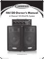
HA120 Owner’s Manual
4-Channel 120-Watt PA System
www.harbingerproaudio.com
9277 Harbinger HA120 manual.indd 1
9/15/10 9:00 AM
9277 Harbinger HA120 manual.indd 2
9/15/10 9:00 AM
Owner’s Manual
Welcome
Congratulations on your purchase of Harbinger’s HA120 4-Channel 120-Watt PA System. Built with rugged, carpet-covered
wood enclosures, the HA120 is the ideal choice for musicians looking for a PA that delivers great sound night after night.
PEAK
PEAK
PEAK
HA12
120 WATT
4 CHANNEL MIXER
MI D
DIGITAL DELAY
PEAK
FX MASTER
TIME
This manual will help you setup your new system. By following our guidelines and suggestions, your new Harbinger will
provide many years of great sound and reliable service.
AUX
IN
REC
OUT
FOOT
SWITCH
Your new PA includes:
Two Speaker Cabinets
One Powered Mixer
Two Speaker Cables
HA12
120 WATT
4 CHANNEL MIXER
MI D
DIGITAL DELAY
PEAK
PEAK
PEAK
PEAK
FX MASTER
TIME
AUX
IN
REC
OUT
HA12
FOOT
SWITCH
120 WATT
4 CHANNEL MIXER
MI D
MI D
DIGITAL DELAY
PEAK
PEAK
PEAKPEAK
PEAKPEAK
PEAK
FX MASTER
TIME
DIGITAL DELAY
PEAK
REC
OUT
AUX
IN
FX MASTER
FOOT
SWITCH
Brief Glossary of Terms
Balanced
A 2-conductor (plus shield), low-impedance connection.
Balanced cables are the preferred method for hum-free
interconnection of a given sound system for their noiserejection characteristics. (Also see Unbalanced.)
extraneous sounds. Two types of EQ shapes are Peak
and Shelving, described below.
TRS (UNBALANCED)
Another common TRS application is for “dual unbalanced”
connections, such as insert send/return jacks or stereo
Resistance in an electrical circuit measured in Ohms (Ω). Y-Cord. These are used for inserting an external processor
into a signal path. (See page 6 of this manual.)
Maintaining proper impedance (between amplifier and
Channel
speakers for example) is important to prevent damage to TS
One of any number of signal paths in an audio circuit,
Acronym for Tip-Sleeve, the two parts of an unbalanced,
the amp.
such as input channel, output channel, recording channel, PEAK EQUALIZER CONTROL
single-conductor (plus shield) phone plug. TS connectors
left channel, right channel, etc.
Increase or decrease of a frequency range centered at a are sometimes called mono or unbalanced plugs or jacks.
IMPEDANCE
DECIBEL (dB)
A term representing the ratio between different audio
levels. For example, a ratio of 1000:1 = 60 dB.
specific point, resulting in an EQ curve that looks like a
hill (increase) or a valley (decrease). (Also see Shelving
Equalizer Control.)
DELAY
SHELVING EQUALIZER CONTROL
Like an echo, this effect duplicates the original signal,
then plays it back at a rate you control. The rate at which
these repeats occur is the “delay time.”
EQUALIZATION
Electronic filters that adjust the level of certain
frequencies. Used for tone enhancement or to reduce
Increase or decrease of all frequencies above or below a
specific point. (Compare to Peak Equalizer Control.)
TRS (BALANCED)
Acronym for Tip-Ring-Sleeve — the three parts of a twoconductor (plus shield) audio plug. TRS phone plugs are
often used for “balanced” connections.
UNBALANCED
A single-conductor (plus shield), high-impedance
connection. Most commonly used for instrument
connections and cable runs of less than 20 feet.
XLR
The three-pin connector universally used for balanced
audio connections. A balanced connection reduces outside
noise and interference. (See Balanced above.)
FCC Statements
1. Caution: Changes or modifications to this unit not expressly approved by the party
responsible for compliance could void the user’s authority to operate the equipment.
2. Note: This equipment has been tested and found to comply with the limits for a Class
B digital device, pursuant to Part 15 of the FCC Rules. These limits are designed to
provide reasonable protection against harmful interference in a residential installation.
This equipment generates, uses, and can radiate radio frequency energy and, if not
installed and used in accordance with the instructions, may cause harmful interference
to radio communications. However, there is no guarantee that interference will not
occur in a particular installation. If this equipment does cause harmful interference to
www.harbingerproaudio.com
9277 Harbinger HA120 manual.indd 1
radio or television reception, which can be determined by turning the equipment off
and on, the user is encouraged to try to correct the interference by one or more of the
following measures:
• Reorient or relocate the receiving antenna.
• Increase the separation between the equipment and receiver.
• Connect the equipment into an outlet on a circuit different from that to which the
receiver is connected.
• Consult the dealer or an experienced radio/TV technician for help.
1
9/15/10 9:00 AM
TIME
HA120
Important Safety Instructions
DANGER
Exposure to extremely high noise levels may cause
permanent hearing loss. Individuals vary considerably
to noise-induced hearing loss but most will lose some
hearing if exposed to intense noise for a sufficient
period of time.
The U.S. Government’s Occupational Safety and Health
Administration (OSHA) has specified the following
permissible noise level exposures:
DURATION PER DAY (HOURS) 8
6
4
3
2
1
SOUND LEVEL (dB) 90
93
95
97 100 103
According to OSHA, any exposure in the above permissible
limits could result in some hearing loss. Ear plugs or
protectors in the ear canal or over the ears must be worn
when operating this amplification system in order to prevent
a permanent hearing loss. If exposure in excess of the limits
as put forth above, to insure against potentially harmful
exposure to high sound pressure levels, it is recommended
that all persons exposed to equipment capable of inducing
high sound pressure levels, such as this amplification
system, be protected by hearing protectors while this unit is
in operation.
THIS SYMBOL IS INTENDED TO ALERT THE USER TO THE PRESENCE
OF NON-INSULATED “DANGEROUS VOLTAGE” WITHIN THE
PRODUCT’S ENCLOSURE THAT MAY BE OF SUFFICIENT MAGNITUDE
TO CONSTITUTE A RISK OF ELECTRIC SHOCK TO PERSONS
THIS SYMBOL IS INTENDED TO ALERT THE USER TO THE PRESENCE
OF IMPORTANT OPERATING AND MAINTENANCE (SERVICING)
INSTRUCTIONS IN THE LITERATURE ACCOMPANYING THE UNIT.
APPARATUS SHALL NOT BE EXPOSED TO DRIPPING OR SPLASHING
AND THAT NO OBJECTS FILLED WITH LIQUIDS, SUCH AS VASES,
SHALL BE PLACED ON THE APPARATUS.
2
9277 Harbinger HA120 manual.indd 2
IMPORTANT SAFETY INSTRUCTIONS
1. Read
all safety and operating instructions before using
this product.
2. A
ll safety and operating instructions should be kept for
future reference.
3. R
ead and understand all warnings listed on the
operating instructions.
4. Follow all operating instructions to operate this product.
5. T his product should not be used near water, i.e. a bathtub,
sink, swimming pool, wet basement, etc.
6. Use only a dry cloth to clean this product.
7. D
o not block any ventilation openings. The product should not
be placed flat against a wall or placed in a built-in enclosure
that will impede the flow of cooling air.
8. D
o not install this product near any heat sources, such
as radiators, heat registers, stoves or any other apparatus
(including heat producing amplifiers) that produces heat.
9. D
o not defeat the safety purpose of the polarized or
grounding-type plug. A polarized plug has two blades with
one wider than the other. A grounding-type plug has two
blades and a third grounding prong. The wide blade or the
third prong are provided for your safety. If the provided plug
does not fit into your outlet, consult an electrician for
replacement of the obsolete outlet.
10. P rotect the power cord being walked on or pinched,
particularly at plugs, convenience receptacles and the point
where they exit from the apparatus. Do not break the ground
pin of the power supply cord.
11. Only use attachments specified by the manufacturer.
12. U
se only with the cart, stand, tripod, bracket,
or table specified by the manufacturer or
sold with the apparatus. When a cart is
used, use caution when moving cart/
apparatus combination to avoid injury
from tip-over.
13. U
nplug this apparatus during lightning storms
or when unused for long periods of time.
14. C
are should be taken so that objects do not fall and liquids
are not spilled into the unit through the ventilation ports or
any other openings.
15. R
efer all servicing to a qualified service professional.
Servicing is required when the apparatus does not operate
normally or has been damaged in any way, including
damage to the power cord or plug, damage due to liquids
spilled or objects dropped inside the unit, dropping the unit,
or anything else that interrupts normal use of the unit.
16. W
ARNING: To reduce the risk of fire or electric shock, do not
expose this apparatus to rain or moisture
17. W
hen a mains plug is used as the disconnect device,
the disconnect device shall remain readily operable.
www.harbingerproaudio.com
9/15/10 9:00 AM
Owner’s Manual
Input Channels
1 LOW EQ
This shelving control gives 15dB of boost or cut at 80Hz
and below. Add warmth to vocals or extra punch to
guitars, drums and synths by turning to the right. Turn to
the left to reduce stage rumble, hum or a muddy sound.
4 FX SEND
This level control sets the amount of signal that will be
sent to the built-in digital delay effect.
5 MIC & LINE INPUT
This MIC input accepts male XLR while the LINE input
accepts a 1/4’’ type phone plug. You can use only one of
the two connectors at a time.
2 HIGH EQ
This shelving control gives 15dB of boost or cut at
12KHz and above. Turn to the right to boost high
frequencies, adding crispness to percussion from drum
machines, cymbals and synths. Turn to the left to cut these
frequencies, reducing sibilance or hiss.
6.PEAK
LED
6
This LED indicates that the input signal is too loud, and may
distort the sound or damage the circuitry. If the PEAK LED
consistently remains lit, reduce the output volume of the
source, or lower the channel volume.
3 VOLUME
This level control determines the proportion of the channel
signal in the mix.
2
1
6
PEAK
3
4
PEAK
PEAK
PEAK
5
MAI N
I N SE RT
3
www.harbingerproaudio.com
A
FUSE :2A
AC 1 20V~50/60HZ 200W
125 WA
9277 Harbinger HA120 manual.indd 3
9/15/10 9:00 AM
HA120
Master Section
1 MASTER EQ
1.
LOW: This shelving control gives 15dB of boost or cut
at 80Hz and below.
44. AUX IN CONTROL
This knob adjusts the level from the AUX Inputs to the
Master Volume.
MID: This is a band peak equalizer with a control range
of +/-15dB at 1KHz.
HIGH: This shelving control gives 15dB of boost or cut
at 12KHz and above.
55 MASTER VOLUME
This knob adjusts the total output Volume. Turn Master
Volume down before turning unit on or off.
2 FX
2.
This controls the signal from the input channels, processed
by the built-in digital delay.
66 AUX IN & REC OUT
The AUX IN Phono Jacks allow MP3/CD players to be
connected to the amplifier. The RECORD OUTPUT RCA
Phono Jacks provide signal output to audio equipment.
The nominal output level and impedance are
-10dBV/600ohms.
FX MASTER: This knob adjusts the mix level of the
effect sound.
TIME: Turn this knob to the right to increase the interval
time between delays, to the left to decrease.
77 FOOTSWITCH
This jack accepts a footswitch (not included) to turn the
digital delay on or off. Compatible with momentary
footswitch (normal open circuit).
1
HA120
2
120 WATT
4 CHANNEL MIXER
MI D
DIGITAL DELAY
AK
PEAK
PEAK
FX MASTER
TIME
3
REC
OUT
AUX
IN
4
7
FOOT
SWITCH
5
6
MAI N
I N SE RT
4
www.harbingerproaudio.com
A
125 WA
HZ 200W
33. POWER INDICATOR
When the power switch at the rear panel is turned on,
this indicator will illuminate.
9277 Harbinger HA120 manual.indd 4
HA120
9/15/10 9:00 AM
Owner’s Manual
Rear Panel
1
1. AC POWER SOCKET
Accepts the removable power cable.
4. MAIN INSERT
4
This unbalanced insert point is a break between the main
out and the built-in amplifier to allow the main output to
be sent to an external signal processor. The insert is a
1/4’’ TRS phone jack which is normally bypassed. When
a jack, such as the one below, is inserted, the signal path
is broken.
2
2. POWER SWITCH
This switches the powered mixer on and off. While on,
the blue LED indicator on the front panel is lit.
3
3. SPEAKER OUTPUT JACKS
Connect both speakers to these jacks. The minimum
impedance load is 4 Ω. Do not connect more than two 8
Ω speakers or damage may occur.
The main output signal appears on the TIP of the plug
and the external signal is returned on the RING. An
HA120
unbalanced 1/4” insert cable is required to connect
to
120 WATT
4 CHANNEL MIXER
equipment with separate send andMI Dreturn jacks as
shown
below:
DIGITAL DELAY
PEAK
PEAK
PEAK
PEAK
INSERT
FX MASTER
TIME
AUX
IN
2
OUT
FOOT
SWITCH
SLEEVE RETURN
(not included)
1
TIPRECSEND
4
MAI N
I N SE RT
A
HA120
125 WAT T S
FUSE :2A
AC 1 20V~50/60HZ 200W
B
USE ONLY WITH 250V FUSE
SPE AKE R
OUT
3
www.harbingerproaudio.com
9277 Harbinger HA120 manual.indd 5
5
9/15/10 9:00 AM
HA120
General Application
(Input)
MAI N
I N SE RT
A
HA120
125 WAT T S
FUSE :2A
AC 1 20V~50/60HZ 200W
B
USE ONLY WITH 250V FUSE
SPE AKE R
OUT
HA120
120 WATT
4 CHANNEL MIXER
MI D
DIGITAL DELAY
PEAK
PEAK
PEAK
PEAK
FX MASTER
TIME
AUX
IN
REC
OUT
FOOT
SWITCH
6
9277 Harbinger HA120 manual.indd 6
www.harbingerproaudio.com
9/15/10 9:00 AM
Owner’s Manual
General Application
(Output)
MAI N
I N SE RT
A
HA120
125 WAT T S
FUSE :2A
AC 1 20V~50/60HZ 200W
B
USE ONLY WITH 250V FUSE
SPE AKE R
OUT
CAUTION: Minimum 4Ω load. Use a maximum of two 8Ω speakers.
4
MI D
DIGITAL DELAY
PEAK
PEAK
www.harbingerproaudio.com
9277 Harbinger HA120 manual.indd 7
PEAK
PEAK
FX MASTER
TIME
7
AUX
IN
9/15/10 9:00 AM
REC
OUT
HA120
Power Amp Specifications
Power Amp
Frequency Response (Mic input to output)
Max Output Power:
120 Watts (@ 4Ω)
20Hz to 20kHz line level output @+4dBu into 600Ω +1/–3dB
88 Watts (@ 8Ω)
20Hz to 20kHz power amp output- 1 watt into 8Ω +1/–3dB
Inputs
Sensitivity @ mixer output +4dBu
Balanced mono:
4 Mic/line channels
Mic/Line:
–50dBu/–35dBu
2 Aux Inputs
Tape in:
–6dBu
RCA Pair
Channel Equalization
Outputs
Record Out:
2 band +/–15dB
Channel Strips (4)
Volume Controls:
Rotary
Master Section
Rotary Fader:
80Hz Shelving
Hi EQ:
12kHz Shelving
Master Equalization
Master
Built-in Digital Effect
Digital Delay:
Low EQ:
(2–150ms)
Noise
3 band +/–15dB
Low EQ:
80Hz Shelving
Mid EQ:
1kHz Peak
Hi EQ:
12kHz Shelving
Microphone Preamp E.I.N.
Master output (all faders down):
–86dBu
Power amp output (all faders down): –55dBu
(150Ω terminated, max gain)
–122dBm
Power Requirements
THD
@120 Watts:
AC120 ~ 50/60Hz
<1%
Dimensions
Crosstalk (1KHz@ 0dBu)
H 8.85” x W 18.9” x D 5.9”
Channel fader down < –63dB
Weight
19 lbs.
8
9277 Harbinger HA120 manual.indd 8
www.harbingerproaudio.com
9/15/10 9:00 AM
Owner’s Manual
Speaker Specifications
RMS power handling
CROSSOVER
80W / 8Ω
3.8K / -12dB per octave
Peak power handling
Frequency response
110W / 8Ω
40Hz–20kHz
Impedance load
Max SPL
8Ω
116dB
Horn construction
Dimensions of speaker box
Compression Driver
H 23.2” x W 14.4” x D 12.8”
Woofer construction:
Net weight
12” cone diaphragm
25.5 lbs (per speaker box)
Magnet weight
30 oz
Block Diagram
www.harbingerproaudio.com
9277 Harbinger HA120 manual.indd 9
9
9/15/10 9:00 AM
HA120
Warranty
So we may serve you better, please register on-line at www.HarbingerProAudio.com
2
Harbinger Limited Warranty Harbinger provides to the original purchaser a two (2) year limited warranty on materials
and workmanship on Harbinger cabinets and loudspeaker components from the date of purchase.
If your covered product is defective, return the defective system to your reseller for in-store exchange, or contact support@
harbingerproaudio.com. If you are uncertain which component is defective, or to obtain instructions for removing
a component, please contact Harbinger Support Headquarters at the above e-mail address for assistance or visit our website
at www.harbingerproaudio.com.
This warranty does not cover service or parts to repair damage caused by neglect, abuse,
normal wear and tear and cosmetic appearance to the cabinetry not directly attributed to
defects in materials or workmanship. Also excluded from coverage are damages caused
directly or indirectly due to any service, repair(s), or modifications of the cabinet, which have
not been authorized or approved by Harbinger. This two (2) year warranty does not cover
service or parts to repair damage caused by accident, disaster, misuse, abuse, burnt voicecoils, over-powering, negligence, inadequate packing or inadequate shipping procedures. The
sole and exclusive remedy of the foregoing limited warranty shall be limited to the repair or
replacement of any defective or non-conforming component. All warranties including, but not
limited to, the express warranty and the implied warranties of merchantability and fitness for a
particular purpose are limited to the two (2) year warranty period. Some states do not allow
limitations on how long an implied warranty lasts, so the above limitation may not apply to
you. There are no express warranties beyond those stated here. In the event that applicable
law does not allow the limitation of the duration of the implied warranties to the warranty
period, then the duration of the implied warranties shall be limited to as long as is provided by
applicable law. No warranties apply after that period.
Retailer and manufacturer shall not be liable for damages based upon inconvenience, loss of
use of product, loss of time, interrupted operation or commercial loss or any other incidental or
consequential damages including but not limited to lost profits, downtime, goodwill, damage
to or replacement of equipment and property, and any costs of recovering, reprogramming, or
reproducing any program or data stored in equipment that is used with Harbinger products.
This guarantee gives you specific legal rights. You may have other legal rights, which vary
from state to state.
Harbinger, P.O. Box 5111, Thousand Oaks, CA 91359-5111
All trademarks and registered trademarks mentioned herein are recognized as the property
of their respective holders.
Made in China
1004-9277
www.harbingerproaudio.com
9277 Harbinger HA120 manual.indd 10
9/15/10 9:00 AM