1
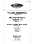
Flow Computer Division V-CONE METERING USER PROGRAM (For ROC809) User Manual Form A6149 April 2004 D301193X012 V-Cone Metering User Program (for ROC809) Revision Tracking Sheet April 2004 This manual may be revised periodically to incorporate new or updated information. The revision date of each page is indicated at the bottom of the page opposite the page number. A significant change in the content of the manual also changes the date that appears on the front cover. Listed below is the revision date of each page. Page Revision Date ii, 1, 5, 6 Rev 2 4/04 All Rev 1 9/03 ROCLINK is a mark owned by one of the Emerson Process Management companies. The Emerson logo is a trademark and service mark of Emerson Electric Co. © Fisher Controls International, LLC. 2003-2004. All rights reserved. Printed in the U.S.A. While this information is presented in good faith and believed to be accurate, Fisher Controls does not guarantee satisfactory results from reliance upon such information. Nothing contained herein is to be construed as a warranty or guarantee, express or implied, regarding the performance, merchantability, fitness or any other matter with respect to the products, nor as a recommendation to use any product or process in conflict with any patent. Fisher Controls reserves the right, without notice, to alter or improve the designs or specifications of the products described herein. ii Rev 2 Rev 1 V-Cone Metering User Program (for ROC809) TABLE OF CONTENTS SECTION 1 — INTRODUCTION..................................................................................1 1.1 1.2 1.3 1.4 1.5 Organization of Manual ............................................................................................................. 1 Program Requirements............................................................................................................... 1 Additional Information .............................................................................................................. 2 Program Overview ..................................................................................................................... 2 Setup Overview.......................................................................................................................... 2 SECTION 2 — DOWNLOADING THE USER PROGRAM ......................................4 2.1 2.2 2.3 Viewing Available Memory ...................................................................................................... 4 Installing the License Key ......................................................................................................... 5 Download Procedure.................................................................................................................. 5 SECTION 3 — CONFIGURING THE PROGRAM.....................................................7 3.1 3.2 3.3 User Program Configuration...................................................................................................... 7 Orifice/Station Configuration .................................................................................................. 10 Orifice Values .......................................................................................................................... 11 SECTION 4 - USER DEFINED POINT TYPES DEFINITIONS .............................12 4.1 Point Type 61: V-Cone User Program Meter Configuration................................................... 12 4.1.1 Description........................................................................................................................... 12 4.1.2 Number of logical points ..................................................................................................... 12 Rev 1 iii V-Cone Metering User Program (for ROC809) [This page is intentionally left blank.] iv Rev 1 V-Cone Metering User Program (for ROC809) SECTION 1 — INTRODUCTION This program allows a ROC809 Remote Operations Controller to calculate a corrected volumeteric flow rate at a specified base pressure and temperature for a McCrometer V-Cone flowmeter. The V-Cone calculation is very similar to an orifice plate calculation, uses many of the same configuration parameters, and produces many of the same calculated values. For this reason, the user program makes use of existing orifice meter run points already provided by the ROC809 firmware. In addition to the standard orifice point parameters, the ROC809 also calculates an actual volumetric flow rate, a fluid velocity, a thermal expansion factor, and the percent pressure loss per the McCrometer specification, “McCrometer Flow Calculations for the V-Cone Flowmeter,” October 2002. 1.1 ORGANIZATION OF MANUAL In this manual, the sections are arranged to provide information in the order in which it is required for first-time users. Once you become familiar with the procedures and the software running in a ROC, the manual may be used as a reference tool. This manual is organized into the following major sections: ♦ Section 1 - Introduction ♦ Section 2 - Downloading the Program ♦ Section 3 - Configuring the Program 1.2 PROGRAM REQUIREMENTS The V-Cone Metering User Program is downloaded into and run from User Program memory located in a ROC809 unit. Requirements for the User Program: ♦ ROC809 Firmware version 1.25 or greater must be installed (check by using ROCLINK 800 to look at “Other Information” display under “Information” under the “ROC” menu). ♦ ROCLINK™ 800 Configuration Software, Version 1.23 or greater (check by using the About function in the Help menu of ROCLINK 800). ♦ A hardware based License Key is required to activate the orifice meter points. Either 6 or 12 meter runs may be licensed for a given unit. Refer to the ROC809 Remote Operations Controller Instruction Manual (A6116) for instructions on installing the License Key. ♦ A hardware based License Key is required to enable the V-Cone user program. Refer to the ROC809 Remote Operations Controller Instruction Manual (A6116) for instructions on installing the License Key. The downloadable program name is V-Cone.tar. This program will require approximately 13 KB of Flash memory and 58 KB of DRAM memory. Rev Rev 1 2 1 V-Cone Metering User Program (for ROC809) 1.3 ADDITIONAL INFORMATION This document is intended to be used along with the following manuals to assist in downloading and configuration of the program. ROCLINK 800 Configuration Software User Manual (Form A6121) – Part Number D301159X012 ROC809 Remote Operations Controller Instruction Manual (Form A6116) – Part Number D301154X012 1.4 PROGRAM OVERVIEW The V-Cone Metering User Program calculates a corrected volumetric flow rate through a McCrometer V-Cone Flowmeter. The program uses an existing orifice meter configuration point to enter configuration information about the V-Cone device, and it uses the corresponding orifice meter values point to store V-Cone meter calculated values and accumulations. Configuration parameters and values, not available through these existing points, are available through the user-defined V-Cone point type. As part of the V-Cone point configuration, the user assigns the V-Cone calculation to an orifice meter point. When the calculation is assigned, the standard AGA3 calculation is bypassed and the McCrometer V-Cone calculation is performed instead. All standard orifice parameters, as well as the additional V-Cone parameters, are available for assignment to Modbus registers, PID control loops, historical archiving, and FST and DS800 database functions. 1.5 SETUP OVERVIEW The following steps are suggested for a typical setup with a ROC809 and a McCrometer V-Cone meter. Read all the procedures and descriptions in this manual before performing these steps. 1. Log in to ROCLINK 800 software. 2. Verify the required AGA3/7/8 License(s) and the V-Cone License are available on the installed hardware license keys using the License Key Administrator. Refer to Section 2.2. 3. Download the V-Cone user program into the ROC809 and start the program. Refer to Section 2.3. 4. Open the V-Cone Configuration screen for each V-Cone meter present. Configure the associated meter run and the flow coefficient. Press Apply. Refer to Section 3.1. 5. Open the Meter Setup Orifice screen for the associated meter run, and configure as described in the ROCLINK 800 Configuration Software User Manual (Form A6121). Note that references to 2 Rev 1 V-Cone Metering User Program (for ROC809) orifice should be replaced with V-Cone (for example, Orifice Diameter will actually represent the V-Cone diameter). 6. Open the Meter Setup Station screen for the associated meter run and configure as described in the ROCLINK 800 Configuration Software User Manual (Form A6121). Rev 1 3 V-Cone Metering User Program (for ROC809) SECTION 2 — DOWNLOADING THE USER PROGRAM This section provides instructions for installing the V-Cone Metering User Program into the ROC. Be sure to read Section 1.2, Program Requirements, before proceeding to the actual program installation. This section includes: ♦ Program Requirements ♦ Viewing Available Memory ♦ Download Procedure NOTE: A PC-compatible computer must be connected to the Operator Interface port (LOI) before the downloading process is started. User program memory must be available (unallocated). 2.1 VIEWING AVAILABLE MEMORY User program memory must be available before installing a user program. This program will require approximately 13 KB of Flash memory and 58 KB of DRAM memory. To view the available memory: 1. Select ROCLINK > Utilities. 2. Select User Program Administrator. When you select User Program Administrator, a screen appears that shows the free memory available for the application program to be loaded. Refer to Figure 1. 4 Rev 1 V-Cone Metering User Program (for ROC809) Figure 1. Viewing Memory in ROCLINK 2.2 INSTALLING THE LICENSE KEY An AGA3/7/8 license key must be present to provide the required number of meter runs. A separate license key is also required to enable the V-Cone user program. Refer to the ROC809 Remote Operations Controller Instruction Manual (A6116) for instructions on installing the License Key. 2.3 DOWNLOAD PROCEDURE Once you have determined the memory required by the desired user program is available (see Section 1.2), you may proceed to select and download the program. 1. In the ROCLINK 800 software User Program Administrator screen, described in Section 2.2, locate the user program file. Refer to Figure 1. 2. Press Browse. The Open File dialog box appears. The Open File display lists the names of all the files that have the .tar extension and are located in the default Drive and Directory. Select the directory path in which the file to be downloaded is located and then select the file. 3. When the desired User Program, V-Cone.tar, appears in the File Name field, press the Open button. The Open File dialog closes, returning you to the User Program Adminstrator screen. 4. Begin loading the selected user program by pressing the Download pushbutton. When the User Program has been downloaded, the Status field in the center of the screen will read Loaded. Rev Rev21 5 V-Cone Metering User Program (for ROC809) 5. Press the Start button. Once the user program has been downloaded to the ROC809 unit, the V-Cone program should be listed under User Programs Installed in ROC. Below that are three buttons: Clear, Start, and Stop. The Clear button removes the user program from the ROC809. The Start button runs the user program. The Stop button halts the user program. See Figure 2. Figure 2. Starting User Program 6 Rev 2Rev 1 V-Cone Metering User Program (for ROC809) SECTION 3 — CONFIGURING THE PROGRAM This section details how to configure the V-Cone Metering User Program using ROCLINK 800 Configuration Software. Note that the user data points and associated parameters will not be available in ROCLINK 800 software until the user program has been downloaded as instructed in Section 2. 3.1 USER PROGRAM CONFIGURATION Once the program is loaded into the ROC, the V-Cone configuration screen becomes available from the Configuration Tree Menu. To open the configuration screen: 1. Expand the ‘User Program’ item in the Configuration Tree Menu (available while on-line with the ROC809 unit). See Figure 3. 2. Find the Program # (default of 1) and notice the program name of ‘V-Cone’. Expand this program. 3. ‘Display #3, V-Cone Configuration’ will appear. Expand this display. The number of calculations licensed to this unit will appear. Select the V-Cone calculation to be set up. Figure 3. Configuration Tree Menu The V-Cone configuration screen allows the user to assign the V-Cone meter to an existing orifice meter run and to enter the flow coefficient. The user is also able to view the actual volumetric flow rate per second, the thermal expansion coefficient, the fluid velocity, and the percent pressure loss. Refer to Figure 4. Rev 1 7 V-Cone Metering User Program (for ROC809) Each field on the V-Cone Configuration screen is described on the following pages. Figure 4. V-Cone Configuration Screen Point Number selects the logical number of the V-Cone point type to configure. V-Cone Tag displays the tag of the associated meter run. This field will be blank if no associated meter has been selected. Associated Meter Run specifies which orifice meter run to use for configuration and storage of calculated values for this V-Cone point. Either the Orifice Meter Run Configuration or Orifice Meter Run Values point type can be selected and any valid logical or parameter number. The selected orifice meter point will then be automatically assigned a “User Defined Device” meter type and the user program will be in control of calculating all values except compressibility and density. Flow Coefficient is a user-entered input to the calculation that is obtained from the V-Cone sizing and calibration report. Units displays the units of measurement for this V-Cone point, either US or Metric. The units selection is made under Meter/Setup/Station for the station to which the associated orifice meter run belongs. Fluid Velocity displays the velocity of the fluid through the V-Cone in feet/second, or meters/second if metric units are selected. 8 Rev 1 V-Cone Metering User Program (for ROC809) Actual Volume Flow Rate displays the volumetric flow rate at the flowing temperature and pressure in ft3/second, or m3/second if metric units are selected. Percent Pressure Loss is the permanent pressure loss at the V-Cone expressed as a percentage of the differential pressure. The Thermal Expansion Factor is the correction for the expansion of the cone and pipe materials, due to differences between operating temperature and calibration temperature. After configuring the V-Cone point and pressing Apply, save the program to Flash Memory on the ROC Flags screen to save the configuration to permanent memory, in case you must perform a Cold Start. Rev 1 9 V-Cone Metering User Program (for ROC809) 3.2 ORIFICE/STATION CONFIGURATION Most of the configuration for the V-Cone meter is done through the standard orifice meter setup screen and the station setup screen for the station to which the orifice meter belongs. See the ROCLINK 800 Configuration Software User Manual (Form A6121) for details. The selection for Meter Type on the Orifice Meter Setup screen will automatically be set to “User Defined Device” by the V-Cone user program when that orifice meter point is selected as the associated meter run. This will have the effect of bypassing the standard AGA3 calculation and allowing the VCone program to write the results of the V-Cone calculation to the orifice meter point type. The following parameters have different meanings for the V-Cone metering user program. Figure 5 . General Tab of Orifice Meter Setup Orifice Diameter represents the diameter of the V-Cone in inches, or mm if metric is selected. 10 Rev 1 V-Cone Metering User Program (for ROC809) Figure 6. Advanced Tab of Orifice Meter Setup Orifice Material represents the type of material of which the V-Cone is constructed (Stainless Steel, Monel, or Carbon Steel). Ref Temp represents the temperature at which the V-Cone diameter was measured. 3.3 ORIFICE VALUES Parameters displayed on the Meter > Values > Orifice Meter screen represent values calculated by the V-Cone Metering user program for orifice meters associated with a V-Cone user point. The Orifice Diameter value on the Factors tab represents the V-Cone diameter in inches, or mm if metric is selected. Values are calculated per the McCrometer V-Cone specification. Rev 1 11 POINT TYPE 61: V-CONE USER PROGRAM METER CONFIGURATION 12 Point Tag Id. Associated Meter Run Flow Coefficient Fluid Velocity 1 2 3 Name 0 Parameter # Velocity Cf Meter Tag Abbrev. R/O R/W R/W R/O Access Program User User Program Program or User Update Point Type 61, V-Cone Metering Configuration Float Float TLP AC Data Type 4 4 3 10 Length Rev 1 0.00 1.00 >0 → 5 Any Positive Floating Point Number 0, 0, 0 ““ 0x20 → 0x7E for each ASCII character 113 or 114, 0→12, Any valid parameter Default Range Point Type 61, V-Cone Metering Configuration Up to 12 logical points of this point type will exist, equal to the number of AGA3/7/8 meter runs licensed. 4.1.2 Number of logical points 1.00 1.00 1.00 1.00 Version Calculated value of fluid velocity in ft3/second or m3/second. User entered flow coeffient, obtained from sizing and clibraiton reports. The associated orifice meter run contains most of the configuration parameters and calculated values for the V-Cone meter and provides the density and compressibility values to the V-Cone calculation. Identification name for the V-Cone meter run. The tag is assigned to the associated orifice meter run and the value is copied to the V-Cone point type 61. Values must be printable ASCII characters. Description of functionality and meaning of values Point type 61 contains the parameters for configuring the gram and houses the results from the GC in terms of the status of the GC. 4.1.1 Description 4.1 SECTION 4 - USER DEFINED POINT TYPES DEFINITIONS V-Cone Metering User Program (for ROC809) Thermal Expansion Factor Actual Volumetric Flow Per Second Pressure Loss Units 4 5 6 7 Rev 1 Name Parameter # Units PLoss Qa Fa Abbrev. R/O R/O R/O R/O Access Program Program Program Program Program or User Update Point Type 61, V-Cone Metering Configuration V-Cone Metering User Program (for ROC809) UINT8 Float Float Float Data Type 1 4 4 4 Length 0 0→1 13 0.00 0.00 1.00 Default 0.0-100.0 Any Positive Floating Point Number Any Positive Floating Point Number Range 1.00 1.00 1.00 1.00 Version Indicates what engineering units the process variables, inputs, and calculation are in. This selection is copied from the station to which the associated orifice meter belongs. 0 = English Units, 1 = Metric Units. The permanent pressure loss respresented as a percentage of the differential pressure. The volumetric flow rate at flowing pressure and temperature in ft3/sec or m3/sec. Calculated value of thermal expansion factor. This factor corrects for the thermal expansion of the cone and pipe materials due to differences between operating temperature and calibration temperature. Description of functionality and meaning of values V-Cone Metering User Program (for ROC809) If you have comments or questions regarding this manual, please direct them to your local sales representative or contact: Emerson Process Management Flow Computer Division Marshalltown, IA 50158 U.S.A. Houston, TX 77065 U.S.A. Pickering, North Yorkshire, UK Y018 7JA Website: www.EmersonProcess.com/flow 14 Rev 1