1
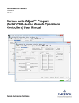
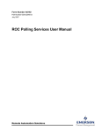
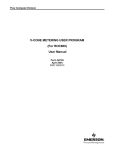
Remote Automation Solutions FLUID PROPERTY CALCULATIONS PROGRAM (For the ROC809) User Manual (QER 07Q014) Form A6141 June 2007 D301190X012 Fluid Property Calculations Program User Manual Revision Tracking Sheet June 2007 This manual may be revised from time to time to incorporate new or updated information. The revision date of each page appears at the bottom of the page opposite of the page number. A change in revision date to any page also changes the date that appears on the front cover of the manual. Listed below is the revision date of each page. Page Revision Initial release April-03 All pages July-03 All pages Jan-07 All pages March-07 All pages June-07 Bristol, Inc., Bristol Babcock Ltd, Bristol Canada, BBI SA de CV and the Flow Computer Division, are wholly owned subsidiaries of Emerson Electric Co. doing business as Remote Automation Solutions (“RAS”), a division of Emerson Process Management. FloBoss, ROCLINK, Bristol, Bristol Babcock, ControlWave, TeleFlow and Helicoid are trademarks of RAS. AMS, PlantWeb and the PlantWeb logo are marks of Emerson Electric Co. The Emerson logo is a trademark and service mark of the Emerson Electric Co. All other marks are property of their respective owners. The contents of this publication are presented for informational purposes only. While every effort has been made to ensure informational accuracy, they are not to be construed as warranties or guarantees, express or implied, regarding the products or services described herein or their use or applicability. RAS reserves the right to modify or improve the designs or specifications of such products at any time without notice. All sales are governed by RAS’ terms and conditions which are available upon request. RAS does not assume responsibility for the selection, use or maintenance of any product. Responsibility for proper selection, use and maintenance of any RAS product remains solely with the purchaser and end-user. ©2003-2007 Remote Automation Solutions, division of Emerson Process Management. All rights reserved. ii June-07 Fluid Property Calculations User Manual Table of Contents Page 1 INTRODUCTION .................................................................................................................................. 1 1.1 Scope and Organization .................................................................................................................... 1 1.2 Product Overview ............................................................................................................................. 1 1.3 Program Requirements ..................................................................................................................... 2 1.3.1 License Keys ........................................................................................................................... 2 2 INSTALLATION ................................................................................................................................... 3 2.1 Installing the License Key ................................................................................................................ 3 2.1.1 Verifying the License Key Installation ................................................................................... 4 2.2 Downloading the fluid_properties.tar Program ................................................................................ 5 3 CONFIGURATION................................................................................................................................ 8 3.1 Configuring ROCLINK 800 ........................................................................................................... 10 3.2 Fluid Setup...................................................................................................................................... 11 3.2.1 Fluid Setup – General Tab..................................................................................................... 12 3.2.2 Fluid Setup – Mass Accumulators Tab ................................................................................. 15 3.3 Configuring a Display for Pure Gas ............................................................................................... 16 3.4 Saving the Configuration ................................................................................................................ 17 4 REFERENCE MATERIALS................................................................................................................ 18 4.1 Parameter Limits............................................................................................................................. 20 4.2 Point Type 60: Fluid Properties ...................................................................................................... 21 June-07 iii Fluid Property Calculations Program User Manual [This page is intentionally left blank.] iv June-07 Fluid Property Calculations User Manual 1 INTRODUCTION 1.1 Scope and Organization This document serves as the user manual for the Fluid Property Calculations Program, which is intended for use in the ROC809 Remote Operations Controllers. This manual describes how to download, install, and configure the Fluid Property Calculations Program (referred to as the “Fluid Property Calculations” or “the program” throughout the rest of this manual). You access and configure this program using ROCLINK™ 800 Configuration Software loaded on an IBM-compatible personal computer (PC) running Windows® 2000 (with Service Pack 2) or XP. The sections in this manual are arranged to provide information in the order in which it is needed for first-time users. Once you become familiar with the procedures, and the software running in the ROC, the manual may be used as a reference tool. The manual has the following major sections: Section 1, Introduction Section 2, Installation Section 3, Configuration Section 4, Reference Materials This manual assumes that you are familiar with the ROC800-series units and their configuration. For more information, refer to the following manuals: ROC809 Remote Operations Controller Instruction Manual (Form A6116). ROCLINK 800 Configuration Software User Manual (Form A6121). 1.2 Product Overview The program calculates density, compressibility, viscosity, and isentropic exponent values for fluids not supported by AGA 8. The program supports up to 12 meter runs with a maximum of 8 streams in any one unit. The following fluid types can be configured: Fluid Steam Temperature Correction Factor Method International Association for the Properties of Water and Steam (IAPWS-97) Pressure Correction Factor Method International Association for the Properties of Water and Steam (IAPWS-97) Saturated Steam International Association for the Properties of Water and Steam (IAPWS-97) International Association for the Properties of Water and Steam (IAPWS-97) Ethylene API 2565 API 2565 Propylene API 2565 API 2565 Butene-1/Light Hydrocarbon API tables 53E and 54E (draft) API Chapter 11.2.2M Benzene ASTM D1555M-00 API Chapter 11.2.1M Para-Xylene ASTM D1555M-00 API Chapter 11.2.1M MTBE or ETBE ISO 91.2, Table C API Chapter 11.2.1M Butadiene ASTM D1550-94 API Chapter 11.2.2M Crude Oil ISO 91.2, Table A API Chapter 11.2.1M Gasoline and Naphta ISO 91.2, Table B API Chapter 11.2.1M June-07 GPA-TP27 (draft version) 1 Fluid Property Calculations Program User Manual The system then stores the values in either an orifice or turbine (linear) meter run for use in calculating volume, mass, and energy values. ROC809 firmware version 2.00 or greater is required to support writing values to density and compressibility. A user-defined point, accessed through the Field Setup screen (see Figure 12), allows you to enter the values the system needs to configure the fluid and assign it to a meter run. 1.3 Program Requirements The Fluid Property Calculations (QER 07Q014) version 1.02 is compatible with ROC800 firmware version 2.00 and with version 1.20 (or greater) of ROCLINK 800 software. A hardware based License Key is required to enable the user program. Program specifics include: File Name Target Unit/ Version User Defined Point (UDP) Flash Used (in bytes) SRAM Used (in bytes) DRAM Used (in bytes) ROCKLINK 800 Version Display Number fluid_properties.tar 2.0 60 67,552 3,528 253,952 1.20 1 Note: You must connect a PC to the ROC809’s LOI port before starting the download. For information on viewing the memory allocation of user programs, refer to the ROCLINK 800 Configuration Software User Manual (Form A6121), Section 7.7. 1.3.1 License Keys License keys, when matched with valid license codes, grant access to applications such as Fluid Property Calculations. The term “license key” refers to the physical piece of hardware that can contain up to seven different licenses (refer to Figure 1). Each ROC809 can have none, one, or two license keys installed. If you remove a license key after enabling an application, the firmware disables the task from running. This prevents unauthorized execution of protected applications in a ROC809. J1 U1 DOC0422A Figure 1. License Key Note: The Fluid Property Calculations program requires both a Fluid Properties license key and an AGA 3/7/8 license key. The program includes a Fluid Properties license key. You must have previously installed the AGA 3/7/8 license key. 2 June-07 Fluid Property Calculations User Manual 2 INSTALLATION This section provides instructions for installing the user program into the ROC. Read Section 1.3 of the manual for program requirements. The downloadable program name is fluid_properties.tar. Notes: An IBM-compatible computer must be connected to the Local Operator Interface (LOI) port before you begin the download. For firmware version 2.0, the Fluid Property Calculations program must be downloaded as program number 1. For later versions of firmware, the program can be loaded into any available empty position. 2.1 Installing the License Key If you order the Fluid Property Calculations program for a new ROC809, your ROC809 is delivered with the license key installed. Go to Section 2.2. If you order the program for an existing ROC809, you must install the license key yourself. Caution Failure to exercise proper electrostatic discharge precautions, such as wearing a grounded wrist strap may reset the processor or damage electronic components, resulting in interrupted operations. When working on units located in a hazardous area (where explosive gases may be present), make sure the area is in a non-hazardous state before performing these procedures. Performing these procedures in a hazardous area could result in personal injury or property damage. To install a license key: 1. Remove power from the ROC809. 2. Remove the wire channel cover. 3. Unscrew the screws from the Central Processing Unit (CPU) faceplate. 4. Remove the CPU faceplate. 5. Place the license key in the appropriate terminal slot (P4 or P6) in the CPU. Incorrect Correct DOC0423A Figure 2. License Key Installation Note: When using a single license key, install it in slot P4. 6. Press the license key into the terminal until it is firmly seated (refer to Figure 2). June-07 3 Fluid Property Calculations Program User Manual 7. Replace the CPU faceplate. 8. Replace the screws on the CPU faceplate. 9. Replace the wire channel cover. 10. Restore power to the ROC809. 2.1.1 Verifying the License Key Installation After you install the license key, you can verify whether the ROC809 recognizes the key. From the ROCLINK 800 screen, select Utilities > License Key Administrator. The License Key Administrator screen displays: Figure 3. License Key Administrator Fluid Properties and AGA_3/7/8 appear in the Application Name column. (For further information on the License Key Administrator screen, refer to the ROCLINK 800 Configuration Software User Manual, Form A6121 Section 2.4.) Note: The value in the App Code field on this screen indicates the total number of stream licenses available on this ROC809. After you verify that the license key is correctly installed and recognized, proceed to Section 2.2 to download the user program. 4 June-07 Fluid Property Calculations User Manual 2.2 Downloading the fluid_properties.tar Program This section provides instructions for installing the fluid_properties.tar program file into the Flash memory on the ROC809. To download the program using ROCLINK 800 software: 1. Connect the ROC to your computer using the LOI port. 2. Start ROCLINK 800 and connect to the ROC809. 3. Select Utilities > User Program Administrator from the ROCLINK 800 menu bar. The User Program Administrator screen displays: Figure 4. User Program Administrator 4. Select any empty program number (in this case, number 1) into which to download the program. Note: If you have an older version of the Fluid Property Calculations Program installed on the ROC, you must uninstall the old version by highlighting the program name and clicking Clear. 5. Click Browse in the Download User Program File frame. The Select User Program File screen displays (see Figure 5). 6. Select the path and user program file to download from the CD-ROM. (Program files are typically located in the Program Files folder on the CD-ROM.) As Figure 5 shows, the screen lists all valid user program files with the .TAR extension: June-07 5 Fluid Property Calculations Program User Manual Figure 5. Select User Program File 7. Click Open to select the program file. The User Program Administrator screen displays. As shown in Figure 6, note that the Download User Program File frame identifies the selected program and that the Download & Start button is active: Figure 6. User Program Administrator 8. Click Download & Start to begin loading the selected programs. The following message displays: 6 June-07 Fluid Property Calculations User Manual Figure 7. Confirm Download 9. Click Yes to begin the download. When the download completes the following message displays: Figure 8. ROCLINK 800 Download Confirmation 10. Click OK. The User Program Administrator screen displays (see Figure 9). Note that: The Device User Program Environment frame reflects the use of system memory. The User Programs Installed in Device frame identifies the installed program(s). The Status field indicates the program is loaded and running. Figure 9. User Program Administrator 11. Proceed to Section 3 to configure the ROC and the program. June-07 7 Fluid Property Calculations Program User Manual [This page is intentionally left blank.] 8 June-07 Fluid Property Calculations User Manual 3 CONFIGURATION After you have loaded the Fluid Property Calculations program on the ROC809, you must configure ROCLINK 800 and the program for proper operation. You access all screens from the main ROCLINK 800 screen. Note: If you are using this program to measure pure gas values, refer to Section 3.3, Configuring a Display for Pure Gas. Figure 10. Configuration Tree Menu June-07 9 Fluid Property Calculations Program User Manual 3.1 Configuring ROCLINK 800 Before configuring the user program, you must configure the ROC809 unit. In addition to the parameters normally configured for a ROC809 unit, configure or verify the following parameters. Note: An AGA license key must be installed in the device to access this screen. Figure 11. Station Setup 1. Login to ROCLINK 800 and connect to the ROC809. 2. Select Meter > Setup > Station from the ROCLINK 800 menu bar. 3. On the General tab, select the Calculation Standard of either ISO5167/ISO9951 for gas or ISO5167/API 12 for liquid. Do not use the AGA3/AGA7 standard. 4. On the Advanced tab, select User for the FPV Method. 5. Click Apply and then OK. The ROCLINK 800 screen appears. 6. Select Meter > Setup > Orifice Meter or Turbine Meter from the ROCLINK 800 menu bar. Assign the meter run(s) to the station that will calculate fluid properties and configure the meter run(s) and inputs. 7. Click Apply then OK. 8. Proceed to Section 3.2 to define fluid properties. 10 June-07 Fluid Property Calculations User Manual 3.2 Fluid Setup Once you have loaded and started the program, ROCLINK 800 provides a display screen in which you configure the Fluid Property Calculations program. Use the Fluid Setup screen to specify which fluid is to be calculated, assign the calculations to a meter run, as well as specify the density and viscosity. The screen also provides program status and displays mass accumulation totals. There are three options that appear at the top of the screen. These options appear on both tabs and define which meter run the information is applied to. To move from one calculation setup to another, use the Configuration Tree Menu or the Point Number drop down box. To access this screen: 1. From the Directory Tree, select User Program > Program #1, fluid_properties > Display #1, Fluid Setup. 2. Double-click Display #1, Undefined. The Fluid Setup screen displays, showing the General tab: Figure 12. Fluid Setup, General tab Note: The Fluid Setup screen has a tab format. Sections 3.2.1 and 3.2.2 discuss the requirements for each tab on the Fluid Setup screen. Field Description Point Number Indicates the specific fluid type you want to define. You can define up to eight. Point Tag System defined name for the selected point number. Associated Meter Run Click “…” to display a TLP dialog box you use to associate a meter run with the selected fluid. June-07 11 Fluid Property Calculations Program User Manual 3.2.1 Fluid Setup – General Tab Use this tab (which displays when you access the Fluid Setup screen) to specify which fluid is to be calculated, assign the calculations to a meter run, specify the density and viscosity, and view program status Note: Figure 13 is an example containing all possible fields and would not normally display as shown. Figure 13. Fluid Setup, General tab (example) 1. Select a Point Number and Associated Meter Run to configure. The program will accept either the Orifice Configuration, Orifice Values, Turbine Configuration, or Turbine Values point types and any parameter designating which meter run the calculation values will be written. Note: The program enables the calculation as soon as you associate it with a meter run. To disable the calculation, select Undefined from the Select TLP dialog box. 2. Select a fluid type. 12 Field Description Fluid Type Defines the type of fluid being measured. Configure the following parameters for each fluid type: Steam For steam, the following fields must be configured: Density and Steam. Saturated Steam For saturated steam, the following fields must be configured: Density and Steam. Ethylene For Ethylene, the following fields must be configured: Density and Liquid Hydrocarbons. Propylene For Propylene configure Density and Liquid Hydrocarbons. Butene-1/ Light Hydrocarbons For Butane-1/Light Hydrocarbons configure Density and Liquid Hydrocarbons. June-07 Fluid Property Calculations User Manual Field Description Fluid Type (continued) Benzene For Benzene configure Density and Liquid Hydrocarbons. Para-Xylene For Para-Xylene configure Density and Liquid Hydrocarbons. MTBE or ETBE For MTBE or ETBE configure Density and Liquid Hydrocarbons. Butadiene For Butadiene configure Density and Liquid Hydrocarbons. Crude Oil For Crude Oil configure Density and Liquid Hydrocarbons. Gasoline and Naphta For Gasoline and Naphta configure Density and Liquid Hydrocarbons. Note: You may assign more than one meter run to a station if you choose the same fluid type. Each meter run would require its own calculation screen. 3. Configure and verify the parameters for the fluid type chosen. Field Description Calculation Status Displays the current status of calculations for a particular point number. Parameter Limits Displays a warning message if any parameters are outside of the current fluid/standards limit. Density Defines how the program obtains a density value. Note: This parameter is not applicable to steam or saturated steam. Steam Densitometer Input Click “…” to assign a densitometer to provide the density. Flowing Density Sets the overall density at flowing conditions, measured by a hydrometer or densitometer. Base Density Sets the density of the fluid at base pressure and temperature. Calculate/Enter Base Sets the density value from the fluid properties. (Enter Base density applies to Liquid Hydrocarbons only.) Densitometer Enables the Densitometer Input field. Defines which input provides the percent of steam flow that is vapor. Note: This parameter applies only to steam or saturated steam. Density Displays the calculated density at flowing conditions. Enthalpy Defines the energy content of the steam on a per unit mass basis. Viscosity Defines the viscosity of the steam. Quality Input Click “…” to assign an input to provide the quality calculation. Quality Value Specifies the percent of steam flow that is vapor. Steam (continued) June-07 13 Fluid Property Calculations Program User Manual Field Description Meter Type Defines the type of meter associated with the calculations. Note: This parameter applies to butene-1 and benzene only. Liquid Hydrocarbons Defines viscosity settings for liquid hydrocarbons. Viscosity Option Set the option to calculate the viscosity. Valid values are Enter Flowing Viscosity and Calculate from Base. Flowing Viscosity Viscosity of the flowing liquid. Base Viscosity Viscosity of the base liquid. CTL Correction for the Temperature of the Liquid. CPL Correction for the Pressure of the Liquid. Alpha Thermal coefficient of expansion. Vapor Pressure Pressure of the vapor being measured. 4. Click Apply to save any changes you have made to this screen. 5. Proceed to Section 3.2.2 to view accumulated totals. 14 June-07 Fluid Property Calculations User Manual 3.2.2 Fluid Setup – Mass Accumulators Tab Use this screen to view (in tonnes) current day, previous day, current month, previous month, and accumulated fluid totals. To access this screen: 1. Select the Mass Accumulators tab on the Fluid Setup screen. Note: All fields displayed on this tab are read-only. 2. Proceed to Section 3.4 to save your configuration. Figure 14. Fluid Setup, Mass Accumulators tab June-07 15 Fluid Property Calculations Program User Manual 3.3 Configuring a Display for Pure Gas The Fluid Property Calculations program can calculate pure gas using Redlich-Kwong compressibility. The displays discussed in Section 3.2 do not configure or display pure gas values. You must create a custom display for pure gas calculations. 1. Follow the instructions for downloading the program given in Section 2.2. 2. Follow the instructions for ROCLINK 800 configuration in Section 3.1. Be sure to select ISO 5167 as the calculation type. 3. Follow the custom display procedure in Section 12.9 of the ROCLINK 800 Configuration Software User Manual (Form A6121). Create fields to associate the calculation with a meter run (Point Type 60, Parameter 2) and enter 2, the value for the pure gas fluid type (Point Type 60, Parameter 1). Add fields for the various gas components (see Section 4, Reference Materials). 4. Click Apply and then OK after the program has been configured. 5. Proceed to Section 3.4 to save your configuration. 16 June-07 Fluid Property Calculations User Manual 3.4 Saving the Configuration Whenever you modify or change the configuration, it is a good practice to save the final configuration to memory. To save the configuration: 1. Select ROC > Flags. The Flags screen displays: Figure 15. Flags screen 2. Click Save Configuration. A verification message displays: Figure 16. Perform screen 3. Click Yes. A confirmation message displays: Figure 17. Flags screen 4. Click OK to begin the save process. The Status field on the Flags screen displays In Progress. When the process ends, the Status field on the Flags screen displays Completed. 5. Click Update on the Flags screen. This completes the process of saving your new configuration. June-07 17 Fluid Property Calculations Program User Manual [This page is intentionally left blank.] 18 June-07 Fluid Property Calculations User Manual 4 REFERENCE MATERIALS This section provides tables of information on the user-defined point type the Fluid Property Calculations program uses: Parameter Limits Errors. Possible error messages received in the Parameter Limits field. Fluid Property Calculations Point Type 60 (Fluid Properties). June-07 19 Fluid Property Calculations Program User Manual 4.1 Parameter Limits Possible error messages that display in the Parameter Limits field. Error Steam Errors Liquid Hydrocarbons Errors Pure Gas Errors Possible error messages when calculating steam. Within Limits All parameters are within an acceptable range. Process Temperature Low Process temperature is below the acceptable range. Process Temperature High Process temperature is above the acceptable range. Process Pressure Low Process pressure is below the acceptable range. Process Pressure High Process pressure is above the acceptable range. Both Pressure and Temperature High Process temperature and pressure are above the acceptable range. Saturation Temperature High Saturation temperature is above the acceptable range. Possible error messages when calculating liquid hydrocarbons. Within Limits All parameters are within an acceptable range. Process Temperature Low Process temperature is below the acceptable range. Process Temperature High Process temperature is above the acceptable range. Process Pressure Low Process pressure is below the acceptable range. Process Pressure High Process pressure is above the acceptable range. Density Low Density is below the acceptable range. Density High Density is above the acceptable range. Max # of Iterations Reached Maximum number of iterations has been reached. Contract Temperature Low Contract temperature is below the acceptable range. Contract Temperature High Contract temperature is above the acceptable range. Contract Pressure Low Contract pressure is below the acceptable range. Contract Pressure High Contract pressure is above the acceptable range. Base Density Un-initialized Base density is not initialized. Critical Temperature Low !!! Critical temperature is low. Saturation Pressure High Saturation pressure is above the acceptable range. Unexpected error An unexpected error has occurred. Possible error messages when calculating pure gas. Within Limits 20 Description All parameters are within an acceptable range. June-07 Fluid Property Calculations User Manual 4.2 Point Type 60: Fluid Properties Point Type 60 Fluid Properties Parameter # 1 Name Meter Run TLP Access System or User Update Data Type Length Range Default Version R/W User TLP 3 TLP 0,0,0 and 0,0,0 1.00 Meter run associated with this fluid. Calculated density and compressibility values will be copied to the selected meter run and its associated station. Meter run station must be configured for “User Method” for Fpv method (Pt type 112, parameter 4). TLP 113,0→11,Any and TLP 114, 0→11,Any and TLP 115, 0→11,Any and TLP 116, 0→11,Any Description of functionality and meaning of values 2 Fluid Type R/W User UIINT8 1 0→25 0 1.00 Type of fluid flowing through the meter. 0 = Steam, 1 = Saturated Steam, 2 = Pure Gas, 3 = Generalized Crude Oils, 4 = Gasoline, 5 = Jet Fuel, 6 = Diesel, 8 = NGL, 9 = Benzene, 10 = Toluene, 11 = m-Xylene, 12 = Styrene, 13 = oXylene, 14 = p-Xylene, 15 = Cyclohexane, 16 = Ethylbenzene, 17 = Cumene, 20 = Water, 22 = Ethylene, 23 = Propylene, 24 = MTBE-ETBE, 25 = Butadiene. 24 N2 Nitrogen R/W User FL 4 0.0 → 100.0 1.0 1.00 Percent of gas present. 25 CO2 Carbon Dioxide R/W User FL 4 0.0 →100.0 0.0 1.00 Percent of gas present. 26 CH4 Methane R/W User FL 4 0.0 → 100.0 96.0 1.00 Percent of gas present. 27 C2H6 Ethane R/W User FL 4 0.0 → 100.0 3.0 1.00 Percent of gas present. 28 C3H8 Propane R/W User FL 4 0.0 → 100.0 0.0 1.00 Percent of gas present. 29 C4H10 n-Butane R/W User FL 4 0.0 → 100.0 0.0 1.00 Percent of gas present. 30 C4H10 i-Butane R/W User FL 4 0.0 → 100.0 0.0 1.00 Percent of gas present. 31 C5H12 n-Pentane R/W User FL 4 0.0 → 100.0 0.0 1.00 Percent of gas present. 32 C5H12 i-Pentane R/W User FL 4 0.0 → 100.0 0.0 1.00 Percent of gas present. 33 C6H14 n-Hexane R/W User FL 4 0.0 → 100.0 0.0 1.00 Percent of gas present. 34 C7H16 n-Heptane R/W User FL 4 0.0 → 100.0 0.0 1.00 Percent of gas present. 35 C8H18 n-Octane R/W User FL 4 0.0 → 100.0 0.0 1.00 Percent of gas present. 36 C9H20 n-Nonane R/W User FL 4 0.0 → 100.0 0.0 1.00 Percent of gas present. 37 C10H22 n-Decane R/W User FL 4 0.0 → 100.0 0.0 1.00 Percent of gas present. 38 H2S Hydrogen Sulfide R/W User FL 4 0.0 → 100.0 0.0 1.00 Percent of gas present. June-07 21 Fluid Property Calculations Program User Manual Point Type 60 Fluid Properties Parameter # 22 Name Access System or User Update Data Type Length Range Default Version Description of functionality and meaning of values 39 H2O Water R/W User FL 4 0.0 → 100.0 0.0 1.00 Percent of gas present. 40 He Helium R/W User FL 4 0.0 → 100.0 0.0 1.00 Percent of gas present. 41 O2 Oxygen R/W User FL 4 0.0 → 100.0 0.0 1.00 Percent of gas present. 42 CO Carbon Monoxide R/W User FL 4 0.0 → 100.0 0.0 1.00 Percent of gas present. 43 H2 Hydrogen R/W User FL 4 0.0 → 100.0 0.0 1.00 Percent of gas present. 44 Ar Argon R/W User FL 4 0.0 → 100.0 0.0 1.00 Percent of gas present. 45 Ne Neon R/W User FL 4 0.0 → 100.0 0.0 1.00 Percent of gas present. 46 SO2 Sulfur Dioxide R/W User FL 4 0.0 → 100.0 0.0 1.00 Percent of gas present. 47 NH3 Ammonia R/W User FL 4 0.0 → 100.0 0.0 1.00 Percent of gas present. 48 HCN Hydrogen Cyanide R/W User FL 4 0.0 → 100.0 0.0 1.00 Percent of gas present. 49 CS2 Carbon Disulfide R/W User FL 4 0.0 → 100.0 0.0 1.00 Percent of gas present. 50 C2H4 Ethylene R/W User FL 4 0.0 → 100.0 0.0 1.00 Percent of gas present. 51 C3H6 Propylene R/W User FL 4 0.0 → 100.0 0.0 1.00 Percent of gas present. 52 C2H2 Acetylene R/W User FL 4 0.0 → 100.0 0.0 1.00 Percent of gas present. 53 CPL Mixture R/O System FL 4 Any IEEE float value 1.0 1.00 Pressure Correction Factor for the oil-water mixture. 54 CPL Oil R/O System FL 4 Any IEEE float value 1.0 1.00 Pressure Correction Factor for the oil. 55 CTL Mixture R/O System FL 4 Any IEEE float value 1.0 1.00 Temperature Correction Factor for the oil-water mixture. 56 CTL Oil R/O System FL 4 Any IEEE float value 1.0 1.00 Temperature Correction Factor for the oil. 57 CTL Water R/O System FL 4 Any IEEE float value 1.0 1.00 Temperature Correction Factor for the water. 58 Hydrometer Correction R/O System FL 4 Any IEEE float value 1.0 1.00 Hydrometer Correction, not used. 59 Brine R/O System FL 4 Any IEEE float value 1.0 1.00 Calculated brine percentage in the water, not used. 60 Alpha R/W Both FL 4 Any IEEE float value 0.0 1.01 Alpha factor for oil CTL calculations, user entered for MTBE-ETBE, calculated for the rest of products. 61 Vapor Pressure R/O System FL 4 Any IEEE float value 0.0 1.01 Vapor Pressure. June-07 Fluid Property Calculations User Manual Point Type 60 Fluid Properties Parameter # Name Access System or User Update Data Type Length Range Default Version Description of functionality and meaning of values 62 Status Message R/O System String 30 Within Limits, Process Temperature Low, Process Temperature High, Saturation Temperature High, Density Low, Density High Within Limits 1.01 Calculation Domain Status Message. 63 Meter Type R/O System U8 1 0->3 0 1.01 0 = Unknown, 1 = Orifice Plate, 2 = Volume Turbine , 3 = Mass Turbine 64 Mass Today R/O System FL 4 Any IEEE float value 0.0 1.01 Mass Today. 65 Mass Yesterday R/O System FL 4 Any IEEE float value 0.0 1.01 Mass Yesterday. 66 Mass Current Month R/O System FL 4 Any IEEE float value 0.0 1.01 Mass Current Month. 67 Mass Previous Month R/O System FL 4 Any IEEE float value 0.0 1.01 Mass Previous Month. 68 Mass Accumulator R/O System FL 4 Any IEEE float value 0.0 1.01 Mass Accumulator. June-07 23 Fluid Property Calculations Program User Manual If you have comments or questions regarding this manual, please direct them to your local sales representative or contact: Emerson Process Management Remote Automation Solutions Marshalltown, Iowa 50158 USA Houston, TX 77065 USA Pickering, North Yorkshire UK Y018 7JA Website: www.EmersonProcess.com/Remote