1
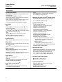
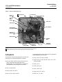
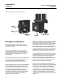
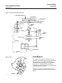
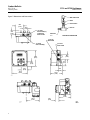
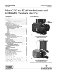
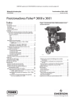
Product Bulletin
3710 and 3720 Positioners
62.1:3710
February 2015
D200437X012
Fisherr 3710 and 3720 Positioners and 3722
Electro-Pneumatic Converter
Fisher 3710 pneumatic and 3720 electro-pneumatic
positioners are designed for use with either diaphragm
or piston rotary actuators. These positioners provide a
valve ball or disk position for a specific input signal.
The 3710 provides a valve position in response to a
pneumatic input signal. The 3720 is created by the
addition of a Fisher 3722 electro-pneumatic converter
to the 3710 positioner. The positioner provides a valve
position in response to a DC current input signal. Either
type can easily be configured as single- or doubleacting for rotary actuators.
SUPPLY
CONNECTION
W6144
FISHER 3720 POSITIONER
MOUNTED ON A 1052 ACTUATOR
SUPPLY
CONNECTION
EXTERNAL
GROUNDING
SCREW
W6058-1
FISHER 3710 POSITIONER
MOUNTED ON A 1066 ACTUATOR
www.Fisher.com
W6145
1/2 NPT OR M20
CONDUIT CONNECTION
FISHER 3722 ELECTRO-PNEUMATIC CONVERTER
Product Bulletin
3710 and 3720 Positioners
62.1:3710
February 2015
D200437X012
Specifications
3720:.
6mm Spool Valve: 1.0 normal m3/hr (36 scfh) at
4.1 bar (60 psig) supply pressure
Available Configuration
3710: J Single- or J double-acting pneumatic rotary
valve positioner
3720: J Single- or J double-acting
electro-pneumatic rotary valve positioner consisting
of a 3710 with a 3722 attached
3722: An electro-pneumatic converter that converts
a 4-20 mA DC input signal to a 0.2 to 1.0 bar
(3 to 15 psig) signal for the pneumatic positioner
Maximum Supply Air Demand(4) (Double-Acting)
6 mm Spool Valve: 20 normal m3/hr (700 scfh) at
4.1 bar (60 psig) supply pressure
Typical Performance(5)
Input Signal
3710:.
Standard: J 0.2 to 1.0 bar (3 to 15 psig) or J 0.4 to
2.0 bar (6 to 30 psig)
Split-Range: J 0.2 to 0.6 bar (3 to 9 psig) and 0.6 to
1.0 bar (9 to 15 psig) or J 0.4 to 1.2 bar (6 to 18 psig)
and 1.2 to 2.0 bar (18 to 30 psig)
3720:.
Standard: J 4-20 mA DC constant current with
30 VDC maximum compliance voltage
Split-Range: J 4-12 mA DC or 12-20 mA DC
3710 Pneumatic Positioner
Independent Linearity: ±0.5% of output span
Hysteresis: 0.5% of output span
Deadband: 0.3% of input span
3720 Electro-Pneumatic Positioner
Independent Linearity: ±1.0% of output span
Hysteresis: 0.6% of output span
Deadband: 0.35% of input span
Electromagnetic Compatibility for 3722
electro-pneumatic converter:
Meets EN 61326-1 (First Edition)
Immunity—Industrial locations per Table 2 of
the EN 61326-1 standard. Performance is
shown in table 1 below.
Emissions—Class A
ISM equipment rating: Group 1, Class A
Equivalent Circuit
3720: 120 ohms shunted by three 5.6 V zener diodes
Output Signal
Pneumatic pressure as required by the actuator up to
full supply pressure
Action(1): Field reversible between direct and reverse
Note: Electromagnetic Compatibility specifications
also apply to the 3720 positioner
Operating Influences
Supply Pressure(2)
Minimum Recommended: 0.3 bar (5 psig) above
actuator requirement
Maximum: 10.3 bar (150 psig) or maximum pressure
rating of the actuator, whichever is lower
Supply Pressure Sensitivity: A 10% change in supply
pressure changes the valve shaft position less than
the following percentages of valve rotation:
3710: 1.0% at 4.1 bar (60 psig) supply pressure
3720: 1.5% at 4.1 bar (60 psig) supply pressure
Supply Medium
3710: Air or Natural Gas(3)
3720: Air
The 3720 positioner is not approved for use with
Natural Gas as the supply medium
Operative Temperature Limits(2)
J -40 to 80_C (-40 to 180_F),
J -50 to 107_C (-58 to 225_F)
Construction Materials
Steady-State Air Consumption(4)
3710:
6 mm Spool Valve: 0.82 normal m3/hr (29 scfh) at
4.1 bar (60 psig) supply pressure
Positioner Base: Low copper aluminum alloy
Cover: Polyester plastic
Feedback Shaft: Stainless steel
Range Spring: Stainless steel
-continued-
2
Product Bulletin
3710 and 3720 Positioners
62.1:3710
February 2015
D200437X012
Specifications (Continued)
Construction Materials (continued)
Input Module Diaphragm, O-rings: J Nitrile or
J Ethylene-propylene (EPDM)
Spool Valve: SST/C72900
Tubing: Copper (standard)
Fittings: Brass (standard)
Gauges: Chrome-plated brass connection with plastic
case
Connectors for diagnostic testing: J Stainless steel or
J Brass
Electrical Classifications for 3722 Converter
CSA—Intrinsically Safe, Explosion-proof, Type n,
Dust-Ignition Proof
FM—Intrinsically Safe, Explosion-proof, Type n,
Non-incendive, Dust-Ignition Proof
ATEX—Intrinsically Safe, Flameproof, Type n
IECEx—Intrinsically Safe, Flameproof, Type n
Refer to tables 2, 3, 4, and 5 for additional approvals
information
Note: These classifications also apply to the 3720
positioner
office for classification/certification specific
information
Note: This classification also applies to the 3720
positioner
Hazardous Area Classification for 3710 Positioner
3710 pneumatic positioners comply with the
requirements of ATEX Group II Category 2 Gas and
Dust
Meets Customs Union technical regulation TP TC
012/2011 for Groups II/III Category 2 equipment
II Gb c T*X
III Db c T*X
Note: These ratings do not apply to the 3720
positioner
Pressure Connections
1/4 NPT internal
Electrical Connection for 3720 Positioner
Housing Classification for 3722 Converter
CSA— Type 3 Encl.
FM— NEMA 3, IP54
ATEX— IP64
IECEx— IP54
Mount instrument with vent on side or bottom if
weatherproofing is a concern
Note: These classifications also apply to the 3720
positioner
Other Classifications/Certifications for 3722
Converter
CUTR— Customs Union Technical Regulations (Russia,
Kazakhstan, and Belarus)
INMETRO—National Institute of Metrology, Quality
and Technology (Brazil)
KGS—Korea Gas Safety Corporation (South Korea)
Contact your Emerson Process Management sales
1/2-14 NPT conduit connection
Rotary Valve Rotation
J 90 degrees (standard) J 60 degrees (optional)
Options
Span Adjuster Assembly: J 0.2 to 1.0 bar (3 to 15
psig) input range or, J 0.4 to 2.0 bar (6 to 30 psig)
input range
Elastomers (O-rings, diaphragm): J standard
temperature range, -40 to 80_C (-40 to 180_F),
J extended temperature range -50 to 107_C (-58 to
225_F)
J Special applications, J Beacon indicator,
J Gauges(6), tire valves, or connectors for diagnostic
testing
Approximate Weight
3710: 2.04 kg (4.5 pounds)
3720: 2.72 kg (6.0 pounds)
NOTE: Specialized instrument terms are defined in ANSI/ISA Standard 51.1 - Process Instrument Terminology.
1. Direct-acting, an increasing input signal extends actuator rod. Reverse-acting, an increasing input signal retracts actuator rod.
2. The pressure and temperature limits in this document and any applicable standard or code limitation should not be exceeded.
3. Natural gas should not contain more than 20 ppm of H2S.
4. Normal m3/hr--Normal cubic meters per hour (0_C and 1.01325 bar, absolute); Scfh--Standard cubic feet per hour (60_F and 14.7 psia).
5. Typical values determined by tests with a 1061 size 30 actuator at 4.1 bar (60 psig) supply pressure. Performance may vary with other actuator types and supply pressures.
6. Gauges not available for high temperature range.
3
Product Bulletin
3710 and 3720 Positioners
62.1:3710
February 2015
D200437X012
Table 1. Fisher 3722 Electro-Pneumatic Converter(1) EMC Summary Results—Immunity
Port
Enclosure
Phenomenon
Electrostatic Discharge (ESD)
IEC 61000-4-2
Radiated EM field
IEC 61000-4-3
Rated power frequency magnetic
field
Burst (fast transients)
I/O signal/control
Basic Standard
Test Level
4 kV contact;
8 kV air
80 to 1000 MHz @ 10V/m with 1 kHz AM at 80%
1400 to 2000 MHz @ 3V/m with 1 kHz AM at 80%
2000 to 2700 MHz @ 1V/m with 1 kHz AM at 80%
Performance
Criteria(2)
A
A
IEC 61000-4-8
60 A/m at 50 Hz
A
A
IEC 61000-4-4
1 kV
Surge
IEC 61000-4-5
1 kV (line to ground only)
B
Conducted RF
IEC 61000-4-6
150 kHz to 80 MHz at 3 volts
A
Specification limit = ±1% of span
1. The information contained in the table also applies to the 3720 positioner.
2. A = No degradation during testing. B = Temporary degradation during testing, but is self-recovering.
Features
n Accurate, Fast Response—3710 and 3720
positioners use field-proven spool valve technology
for a simple design that gives accurate,
fast-responding operation with high cycle life.
These positioners are able to withstand the severe
vibrations of most plant environments.
n Modular Construction—The 3710 positioner
converts easily to a 3720 positioner by adding the
3722 electro-pneumatic converter. The converter
mounts over the instrument and supply ports in the
3710 positioner base. This provides a simple,
compact, and cost-effective field conversion from
pneumatic to electro-pneumatic valve positioning.
n Corrosion-Resistant Construction with Air
Purge—Case, components, and gasket materials
withstand harsh environments. Proven engineered
resins and 300 Series stainless steel construction is
used throughout each unit. Die castings are low
copper aluminum alloy to maximize corrosion
resistance. Positioner bleed air purges internal
positioner parts. As an option with some Fisher
actuators, bleed air also purges the actuator
housing for additional protection.
4
n Extended Temperature Capability—With EPDM
O-rings and input module diaphragm, 3710 and
3720 positioners can be used in low-temperature
and high-temperature applications.
n Meets Special Application Requirements— 3710 and
3720 positioners with EPDM O-rings and input
module diaphragm can be used in applications with
special material requirements as in the food and
beverage industry, pharmaceuticals, and tobacco
processing.
n Easy Positioner Adjustments—With the cover
removed (figure 1), all internal components are
easily accessed. Zero and span adjustments are
made by hand with no tools required.
n Stable Operation—Changes in supply pressure and
ambient temperature have minimal effect on
positioner operation.
n Control Valve Diagnostic Testing Capability—To
support diagnostic testing of
valve/actuator/positioner packages, connectors,
piping, and other hardware can be installed
between the 3710 positioner and the actuator. A
typical connector installation is shown in figure 5.
n Valve Position Indicator—Standard, low-profile
indicator or optional, beacon-style indicator mount
easily to the positioner cover.
Product Bulletin
3710 and 3720 Positioners
62.1:3710
February 2015
D200437X012
Figure 1. Features and Adjustments
NAMEPLATE
AREA
1
2
SPAN ADJ ASSY
ACTION BLOCK
MOUNTING SCREW HOLE
SCREENED
VENT
OPENING
SPOOL VALVE
ZERO ADJ PIVOT
INPUT MODULE
SPAN ADJ SHAFT
(THREADED ROD)
ZERO ADJUSTER
LOCK NUT
ZERO ADJUSTER
SUMMING
BEAM
FEEDBACK
ARM ASSEMBLY
MOUNTING
SCREW HOLE
CAM
MOUNTING
SCREW HOLE
Notes:
1 The Span Adj Assy is made up of the range spring, span adj shaft (threaded rod) and span adj knob.
2 The Span Adj Assy features a red color-coded range spring for a 6 to 30 psig input signal.
W5947
Actuators
A mounting plate is used to mount the 3710 positioner
to the following Fisher actuators:
The positioner mounts integrally to the actuator cover
plate (figure 2) of the following Fisher actuators:
n 1031, size 26, 33, 45, 60, and 80
n 1051 and 1052, size 30: The size 30 actuator is no
longer manufactured by Emerson Process
Management. The 3710 positioner is available for
field installation on existing size 30 actuators.
n 1032, size 45, 70, 185, 280, 425, 680, 1125, 1370,
2585, and 4585
n 1051, size 33
n 1052, size 20, 33
n 1051, size 40 and 60
n 1052, size 40, 60, and 70
n 1061, size 30, 40, 60, and 68
n 1061, size 80, 100
n 1066, size 20, 27, and 75
n 2052, size 1, 2, and 3
5
Product Bulletin
3710 and 3720 Positioners
62.1:3710
February 2015
D200437X012
Figure 2. Mounting the Positioner Base Plate
MOUNTING
SCREW
FEEDBACK
SHAFT
W6059
MOUNTING
SCREWS
Principle of Operation
Refer to the positioner schematic (figure 3). The
operational description here follows the schematic
layout and orientation.
The 3710 pneumatic positioner is a force-balance
instrument that provides a control valve position
proportional to a pneumatic input signal. The balance
of opposing forces in the positioner occurs at the
summing beam.
One force applied to the summing beam is developed
from the input signal pressure on the diaphragm. The
other force is from the feedback spring and is
proportional to the position of the feedback lever.
When the input pressure is increased to the diaphragm
of the input module, the diaphragm strokes down,
increasing the effective force from the input module
and compressing the feedback spring. The summing
beam moves the spool down in the spool body,
opening output port B to supply air to the left side of
the actuator. At the same time, output port A of the
spool valve opens, allowing the right side of the
actuator to vent to atmosphere.
6
TIE BAR
EXTENSION
POSITIONER
MOUNTING PLATE
The piston in the actuator moves to the right, rotating
the feedback shaft and cam counterclockwise. This
rotation causes the feedback lever to rotate clockwise,
increasing the compression on the feedback spring.
These rotations continue until the additional force
from the spring balances with the input module force
on the summing beam. When the forces are equal, the
summing beam returns to its steady state or neutral
position and the actuator is held at a new position.
In a 3720 positioner, the 3722 converter receives the
milliampere (mA), direct current (DC), input signal and
provides a proportional pneumatic output signal
through a nozzle/flapper arrangement. Nozzle
pressure from the converter module travels through
the converter housing to provide the input signal
pressure to the 3710 pneumatic positioner.
The feedback lever position is determined by the
location or rise of the cam (figure 4) which is attached
to the feedback shaft. When the two opposing forces
are equal or at a steady state, the summing beam
holds the spool in a neutral position. At steady state, a
small flow of air passes from supply through both
outputs of the spool valve to the actuator, holding the
actuator at a constant position. At the same time,
another small flow of air exhausts out each end of the
spool valve.
Product Bulletin
3710 and 3720 Positioners
62.1:3710
February 2015
D200437X012
Figure 3. Fisher 3710 Positioner Schematic
INPUT SIGNAL PRESSURE
INPUT MODULE
SUMMING BEAM
PIVOT
SPOOL VALVE
FEEDBACK
SPRING
A
B
SUPPLY
SPAN ADJ
CAM
PIVOT
FEEDBACK
LEVER
ZERO ADJ
PIVOT
OUTPUT B
PISTON ACTUATOR
A5944-1
Figure 4. Cam
OUTPUT A
Installation
The supply pressure medium must be a clean, dry,
filtered air, or noncorrosive gas (3710 positioner only).
If the supply source is capable of exceeding the
maximum actuator operating pressure or positioner
supply pressure, take appropriate steps during
installation to protect the positioner and all connected
equipment against overpressure.
Positioner connections including connections for
diagnostic testing and overall dimensions are shown in
figure 5.
CAM ROLLER
A6045
7
Product Bulletin
3710 and 3720 Positioners
62.1:3710
February 2015
D200437X012
Figure 5. Dimensions and Connections
BODY PROTECTOR
BODY
PIPE BUSHING
84.0
(3.31)
PIPE TEE
50.5
(1.99)
1/4-18 NPT
OUTPUT CONN (A)
PLUGGED ON
SINGLE ACTING
41.8
(1.65)
PIPE NIPPLE
DIAGNOSTIC CONNECTOR
12B8055-A
B2385
1/4-18 NPT
INSTR CONN
1/4-18 NPT
OUTPUT CONN (B)
1/4-18 NPT
SUPPLY CONN
48.0
(1.89)
167.9
(6.61)
70.3
(2.77)
45.2
(1.78)
68.7
(2.70)
41.8
(1.65)
167.9
(6.61)
132.6
(5.22)
A5945-1
132.6
(5.22)
146.1
(5.75)
11B5496-A
A6149-1
8
39.6
(1.56)
mm
INCH
Product Bulletin
3710 and 3720 Positioners
62.1:3710
February 2015
D200437X012
Ordering Information
6. Ambient temperature range
When ordering, specify:
7. Special application material requirements such as
EPDM elastomers
Required Application Information
8. Supply pressure regulator and options such as
gauges or tire valves, if required
1. Positioner type number
9. Connectors for diagnostic testing, if required
2. Pneumatic or DC current input signal range
3. Direct- or reverse-acting
4. Actuator type, size, and degrees of rotation
5. Maximum supply pressure available
Construction Specifications
Refer to the construction details given in the
Specifications. If different materials of construction are
required, contact your Emerson Process Management
sales office.
9
Product Bulletin
3710 and 3720 Positioners
62.1:3710
February 2015
D200437X012
Table 2. Hazardous Area Classifications for Fisher 3722 Electro-Pneumatic Converter(1)—CSA (Canada)
Certification Body
CSA
Certification Obtained
Intrinsically Safe
Ex ia IIC T4/T5/T6 per drawing GE28591
Ex ia Intrinsically Safe
Class I, II Division 1 GP A,B,C,D,E,F,G T4/T5/T6
per drawing GE28591
Explosion-proof
Ex d IIC T5
Class I, Division 1, GP A,B,C,D T5
Type n
Ex nA IIC T6
Class I, Division 2, GP A,B,C,D T6
Class II, Division 1, GP E,F,G T5
Entity Rating
Vmax = 30 VDC
Imax = 150 mA
Pi = 1.25 W
Ci = 0 nF
Li = 0 mH
Temperature Code
T4 (Tamb ≤ 82°C)
T5 (Tamb ≤ 62°C)
T6 (Tamb ≤ 47°C)
---
T5 (Tamb ≤ 82°C)
---
T6 (Tamb ≤ 82°C)
T6 (Tamb ≤ 82°C)
---
Class II, Division 2, GP F,G T6
T5 (Tamb ≤ 82°C)
T6 (Tamb ≤ 82°C)
1. These hazardous area classification also apply to 3720 positioners.
Table 3. Hazardous Area Classifications for Fisher 3722 Electro-Pneumatic Converter(1)—FM (United States)
Certification Body
Certification Obtained
Intrinsically Safe
Class I Zone 0 AEx ia IIC T4/T5/T6 per drawing GE28590
Class I, II, III Division 1 GP A,B,C,D,E,F,G T4/T5/T6
per drawing GE28590
FM
Explosion-proof
Class I Zone 1 AEx d IIC T5
Class I, Division I, GP A,B,C,D T5
Type n
Class I Zone 2 AEx nA IIC T5
Class I, Division 2, GP A,B,C,D T5
Class II, Division 1, GP E,F,G T5
Class II, Division 2, GP F,G T5
Entity Rating
Vmax = 30 VDC
Imax = 150 mA
Pi = 1.25 W
Ci = 0 nF
Li = 0 mH
Temperature Code
T4 (Tamb ≤ 82°C)
T5 (Tamb ≤ 62°C)
T6 (Tamb ≤ 47°C)
---
T5 (Tamb ≤ 82°C)
---
T5 (Tamb ≤ 82°C)
---
T5 (Tamb ≤ 82°C)
1. These hazardous area classification also apply to 3720 positioners.
Table 4. Hazardous Area Classifications for Fisher 3722 Electro-Pneumatic Converter(1)—ATEX
Certification
Certification Obtained
Entity Rating
Temperature Code
II 1 G & D
Intrinsically Safe
Gas
Ex ia IIC T4/T5/T6 Ga
Dust
Ex ia IIIC Da T120°C (Tamb ≤ 82°C) / T100°C (Tamb ≤ 62°C) /
T85°C (Tamb ≤ 47°C)
Ui = 30 VDC
Ii = 150 mA
Pi = 1.25 W
Ci = 0 nF
Li = 0 mH
T4 (Tamb ≤ 82°C)
T5 (Tamb ≤ 62°C)
T6 (Tamb ≤ 47°C)
---
II 2 G & D
ATEX
Flameproof
Gas
Ex d IIC T5 Gb
Dust
Ex tb IIIC Db T82°C (Tamb ≤ 79°C)
II 3 G & D
Type n
Gas
Ex nA IIC T6 Gc
Dust
Ex tc IIIC Dc T85°C (Tamb ≤ 82°C)
1. These hazardous area classification also apply to 3720 positioners.
10
T5 (Tamb ≤ 82°C)
-----
T6 (Tamb ≤ 82°C)
-----
Product Bulletin
3710 and 3720 Positioners
62.1:3710
February 2015
D200437X012
Table 5. Hazardous Area Classifications for Fisher 3722 Electro-Pneumatic Converter(1)—IECEx
Certification
Certification Obtained
Intrinsically Safe
Gas
Ex ia IIC T4/T5/T6 Ga
IECEx
Flameproof
Gas
Ex d IIC T5 Gb
Type n
Gas
Ex nA II T6 Gc
Entity Rating
Ui = 30 VDC
Ii = 150 mA
Pi = 1.25 W
Ci = 0 nF
Li = 0 mH
Temperature Code
T4 (Tamb ≤ 82°C)
T5 (Tamb ≤ 62°C)
T6 (Tamb ≤ 47°C)
---
T5 (Tamb ≤ 82°C)
---
T6 (Tamb ≤ 82°C)
1. These hazardous area classification also apply to 3720 positioners.
11
Product Bulletin
62.1:3710
February 2015
3710 and 3720 Positioners
D200437X012
Neither Emerson, Emerson Process Management, nor any of their affiliated entities assumes responsibility for the selection, use or maintenance
of any product. Responsibility for proper selection, use, and maintenance of any product remains solely with the purchaser and end user.
Fisher is a mark owned by one of the companies in the Emerson Process Management business unit of Emerson Electric Co. Emerson Process Management,
Emerson, and the Emerson logo are trademarks and service marks of Emerson Electric Co. All other marks are the property of their respective owners.
The contents of this publication are presented for informational purposes only, and while every effort has been made to ensure their accuracy, they are not
to be construed as warranties or guarantees, express or implied, regarding the products or services described herein or their use or applicability. All sales are
governed by our terms and conditions, which are available upon request. We reserve the right to modify or improve the designs or specifications of such
products at any time without notice.
Emerson Process Management
Marshalltown, Iowa 50158 USA
Sorocaba, 18087 Brazil
Chatham, Kent ME4 4QZ UK
Dubai, United Arab Emirates
Singapore 128461 Singapore
www.Fisher.com
E
121991, 2015 Fisher Controls International LLC. All rights reserved.