1
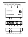
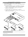
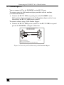
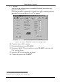
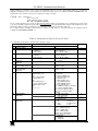
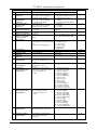
Kramer Electronics, Ltd.
USER MANUAL
Model:
VS-201YC
2x1 s-Video Switcher
Contents
Contents
1
2
2.1
3
4
5
5.1
6
6.1
6.2
6.3
7
8
9
Introduction
Getting Started
Quick Start
Overview
Your VS-201YC 2x1 s-Video Switcher
Connecting the VS-201YC 2x1 s-Video Switcher
Connecting a PC
Flash Memory Upgrade
Downloading from the Internet
Connecting the PC to the RS-232 Port
Upgrading Firmware
Technical Specifications
Table of Hex Codes for Serial Communication
VS-201YC Communication Protocol
1
1
1
3
4
6
7
8
8
8
9
13
14
14
Figures
Figure 1: VS-201YC 2x1 s-Video Switcher
Figure 2: VS-201YC 2x1 s-Video Switcher (Top Side Panel)
Figure 3: VS-201YC 2x1 s-Video Switcher (Lower Side Panel)
Figure 4: VS-201YC 2x1 s-Video Switcher Underside
Figure 5: Connecting the VS-201YC 2x1 s-Video Switcher
Figure 6: Connecting a PC without using a Null-modem Adapter
Figure 7: Splash Screen
Figure 8: Atmel – Flip Window
Figure 9: Device Selection Window
Figure 10: Selecting the Device from the Selection Window
Figure 11: Loading the Hex
Figure 12: RS-232 Window
Figure 13: Atmel – Flip Window (Connected)
Figure 14: Atmel – Flip Window (Operation Completed)
4
4
4
5
6
7
9
9
9
10
10
11
11
12
Tables
Table 1: VS-201YC 2x1 s-Video Switcher Features
Table 2: VS-201YC 2x1 s-Video Switcher Underside Features
Table 3: VS-201YC 2x1 s-Video Switcher Technical Specifications
Table 4: Hex Codes
Table 5: Protocol Definitions
Table 6: Instruction Codes for Protocol 2000
5
5
13
14
14
15
i
Introduction
1
Introduction
Welcome to Kramer Electronics (since 1981): a world of unique, creative and
affordable solutions to the infinite range of problems that confront the video,
audio and presentation professional on a daily basis. In recent years, we have
redesigned and upgraded most of our line, making the best even better! Our
500-plus different models now appear in 8 Groups1, which are clearly defined
by function.
Congratulations on purchasing your Kramer VS-201YC 2x1 s-Video Switcher,
which is ideal for the following applications:
Presentation and display systems
CCTV and home theater applications
Rental and staging applications
The package includes the following items:
VS-201YC 2x1 s-Video Switcher
Power adapter (12V DC Input)
This user manual2
2
Getting Started
We recommend that you:
Unpack the equipment carefully and save the original box and
packaging materials for possible future shipment
Review the contents of this user manual
Use Kramer high performance high resolution cables3
2.1 Quick Start
This quick start chart summarizes the basic setup and operation steps.
1 GROUP 1: Distribution Amplifiers; GROUP 2: Video and Audio Switchers, Matrix Switchers and Controllers; GROUP 3:
Video, Audio, VGA/XGA Processors; GROUP 4: Interfaces and Sync Processors; GROUP 5: Twisted Pair Interfaces;
GROUP 6: Accessories and Rack Adapters; GROUP 7: Scan Converters and Scalers; and GROUP 8: Cables and Connectors
2 Download up-to-date Kramer user manuals from our Web site: http://www.kramerelectronics.com
3 The complete list of Kramer cables is on our Web site at http://www.kramerelectronics.com
1
Getting Started
2
KRAMER: SIMPLE CREATIVE TECHNOLOGY
Overview
3
Overview
The VS-201YC is a 2x1 switcher for s-Video signals that lets you switch
either the signal at input 1 or input 2 to the output.
In particular, the VS-201YC:
Features video input and output signals on 4p connectors
Has two selector buttons for selecting the input to route to the output
To achieve the best performance:
Connect only good quality connection cables, thus avoiding
interference, deterioration in signal quality due to poor matching,
and elevated noise levels (often associated with low quality cables)
Avoid interference from neighboring electrical appliances that may
adversely influence signal quality and position your Kramer
VS-201YC away from moisture, excessive sunlight and dust
Caution – No operator-serviceable parts inside unit.
Warning – Use only the Kramer Electronics input power
wall adapter that is provided with this unit1.
Warning – Disconnect power and unplug unit from wall
before installing or removing device or servicing unit.
1 For example: model number AD2512C, part number 2535-000251
3
Your VS-201YC 2x1 s-Video Switcher
4
Your VS-201YC 2x1 s-Video Switcher
Figure 1, Figure 2, Figure 3 and Table 1 define the VS-201YC:
Figure 1: VS-201YC 2x1 s-Video Switcher
Figure 2: VS-201YC 2x1 s-Video Switcher (Top Side Panel)
Figure 3: VS-201YC 2x1 s-Video Switcher (Lower Side Panel)
4
KRAMER: SIMPLE CREATIVE TECHNOLOGY
Your VS-201YC 2x1 s-Video Switcher
Table 1: VS-201YC 2x1 s-Video Switcher Features
#
1
2
3
4
5
6
7
8
Feature
12VDC
RS-232 DB 9F Port
OUTPUT 4p Connector
INPUT 2 4p Connector
INPUT 1 4p Connector
IN 1 SELECT Button
IN 2 SELECT Button
ON LED
Function
+12V DC connector for powering the unit
1
Connects to the PC or the Remote Controller
Connect to the s-Video acceptor
Connect to the s-Video source 2
Connect to the s-Video source 1
Press to select input 1 to switch to the output
Press to select input 2 to switch to the output
Illuminates when receiving power
Figure 4 and Table 2 define the underside of the VS-201YC:
Figure 4: VS-201YC 2x1 s-Video Switcher Underside
Table 2: VS-201YC 2x1 s-Video Switcher Underside Features
#
1
Feature
Function
PROGRAM Select OFF (by sliding to the left) for normal operation (the factory default), and ON
Switch
(by sliding to the right) to upgrade to the latest Kramer firmware (see section 6)
1 Via a null-modem connection
5
Connecting the VS-201YC 2x1 s-Video Switcher
5
Connecting the VS-201YC 2x1 s-Video Switcher
To connect1 the VS-201YC 2x1 s-Video Switcher, as the example in Figure 5
illustrates, do the following:
1. Connect the two s-Video sources to the s-Video INPUT 4p connectors (for
example, an s-Video player to INPUT 1 and an s-Video player to INPUT 2).
2. Connect the s-Video OUTPUT 4p connector to the acceptor (for
example, an s-Video recorder).
3. If required, connect a PC to the RS-232 port2, see section 5.1.
4. Connect the 12V DC power adapter to the power socket2 and connect the
adapter to the mains electricity.
Figure 5: Connecting the VS-201YC 2x1 s-Video Switcher
1 Switch OFF the power on each device before connecting it to your VS-201YC. After connecting your VS-201YC, switch on
its power and then switch on the power on each device
2 Not illustrated in Figure 5
6
KRAMER: SIMPLE CREATIVE TECHNOLOGY
Connecting the VS-201YC 2x1 s-Video Switcher
5.1 Connecting a PC
You can connect a PC to the VS-201YC via the RS-232 port.
To connect using the Null-modem adapter provided with the machine
(recommended method):
Connect the RS-232 DB9 rear panel port on the VS-201YC to the
Null-modem adapter and connect the Null-modem adapter with a 9-wire
flat cable to the RS-232 DB9 port on your PC
To connect without using a Null-modem adapter:
Connect the RS-232 DB9 port on your PC to the RS-232 DB9 rear panel
port on the VS-201YC, as Figure 6 illustrates
PIN 5 Connected to PIN 5 (Ground)
PIN 3 Connected to PIN 2
PIN 2 Connected to PIN 3
Female DB9 (From PC)
Male DB9
PIN 4 Connected to PIN 6
PINS 8, 7, 1 Connected together
If a Shielded cable is used, connect the shield to PIN 5
Figure 6: Connecting a PC without using a Null-modem Adapter
7
Flash Memory Upgrade
6
Flash Memory Upgrade
The VS-201YC firmware is located in FLASH memory, which lets you
upgrade1 to the latest Kramer firmware version in minutes! The process
involves:
Downloading from the Internet (see section 6.1)
Connecting the PC to the RS-232 port (see section 6.2)
Upgrading Firmware (see section 6.3)
6.1 Downloading from the Internet
You can download the up-to-date file2 from the Internet. To do so:
1. Go to our Web site at http://www.kramerelectronics.com and download the
file: “FLIP_VS201YC.zip” from the Technical Support section.
2. Extract the file: “FLIP_VS201YC.zip” to a folder (for example, C:\Program
Files\Kramer Flash).
3. Create a shortcut on your desktop to the file: “FLIP.EXE”.
6.2 Connecting the PC to the RS-232 Port
Before installing the latest Kramer firmware version on a VS-201YC unit, do
the following:
1. Connect the RS-232 DB9 rear panel port on the VS-201YC unit to the
Null-modem adapter and connect the Null-modem adapter with a 9-wire
flat cable to the RS-232 DB9 COM port on your PC (see section 5.1).
2. On the underside panel, slide the PROGRAM switch to the right to ON.
3. Connect the power on the VS-201YC unit.
1 Upgrade should be carried out by skilled technical personnel. Failure to upgrade correctly will result in the malfunction of
the machine
2 The files indicated in this section are given as an example only. These file names are liable to change from time to time
8
KRAMER: SIMPLE CREATIVE TECHNOLOGY
Flash Memory Upgrade
6.3 Upgrading Firmware
Follow these steps to upgrade the firmware:
1. Double click the desktop icon: “Shortcut to FLIP.EXE”.
The Splash screen appears as follows:
Figure 7: Splash Screen
2. After a few seconds, the Splash screen is replaced by the “Atmel – Flip” window:
Figure 8: Atmel – Flip Window
3. Press the keyboard shortcut key F2 (or select the “Select” command from the
Device menu, or press the integrated circuit icon in the upper right corner of
the window). The “Device Selection” window appears:
Figure 9: Device Selection Window
9
Flash Memory Upgrade
4. Click the button next to the name of the device and select from the list:
AT89C51RD2:
AT89C51RD2
T89C51RD2
Figure 10: Selecting the Device from the Selection Window
5. Click OK and select “Load Hex” from the File menu.
A
Figure 11: Loading the Hex
10
KRAMER: SIMPLE CREATIVE TECHNOLOGY
Flash Memory Upgrade
6. The Open File window opens. Select the correct HEX file that contains the
updated version of the firmware for VS-201YC (for example,
201YCM_V1p2.hex) and click Open.
7. Press the keyboard shortcut key F3 (or select the “Communication / RS232”
command from the Settings menu, or press the keys: Alt SCR).
The “RS232” window appears. Change the COM port according to the
configuration of your computer and select the 9600 baud rate:
Figure 12: RS-232 Window
8. Click Connect.
In the “Atmel – Flip” window, in the Operations Flow column, the Run button
is active, and the name of the chip appears as the name of the third column:
AT89C51RD2.
Verify that in the Buffer Information column, the “HEX File: VS201YC.hex”
appears.
A
VS201YC.hex
Figure 13: Atmel – Flip Window (Connected)
11
Flash Memory Upgrade
9. Click Run.
After each stage of the operation is completed, the check-box for that stage
becomes colored green1.
When the operation is completed, all 4 check-boxes will be colored green and
the status bar message: Memory Verify Pass appears2:
A
VS201YC.hex
Figure 14: Atmel – Flip Window (Operation Completed)
10. Close the “Atmel – Flip” window.
11. Disconnect the power to the VS-201YC.
12. Disconnect the RS-232 rear panel port on the VS-201YC unit from the
Null-modem adapter.
13. Switch to OFF on the machine underside.
14. Connect the power to the VS-201YC.
1 See also the blue progress indicator on the status bar
2 If an error message: “Not Finished” shows, click Run again
12
KRAMER: SIMPLE CREATIVE TECHNOLOGY
Technical Specifications
7
Technical Specifications
Table 3 includes the technical specifications1.
Table 3: VS-201YC 2x1 s-Video Switcher Technical Specifications
INPUTS:
OUTPUT:
MAX. OUTPUT LEVEL:
BANDWIDTH (-3dB):
DIFF. GAIN:
DIFF. PHASE:
K-FACTOR:
S/N RATIO:
CROSSTALK (all hostile):
COUPLING:
POWER SOURCE:
DIMENSIONS:
WEIGHT:
ACCESSORIES:
OPTIONS:
2 YC, 1Vpp/75 (Y), 0.3Vpp/75 (C) on 4p connectors
1 YC 1Vpp/75 (Y), 0.3Vpp/75 (C) on an 4p connector
2.4Vpp
520MHz
0.03%
0.02 Deg.
<0.05%
78dB
-53dB
DC
12V, 110mA
12cm x 7.15cm x 2.76cm (4.7" x 2.8" x 1.08"), W, D, H
0.3 kg. (0.67 lbs.) approx.
Power supply, mounting bracket
Rack Adapter models: RK-1T2PT, RK-2T1PT, and/or RK-3T
1 Specifications are subject to change without notice
13
Table of Hex Codes for Serial Communication
8
Table of Hex Codes for Serial Communication
Table 4 lists the Hex values for switching on the VS-201YC.
Table 4: Hex Codes
IN 1
IN 2
OUT
2
1
9
VS-201YC Communication Protocol
The VS-201YC is compatible with Kramer’s Protocol 2000 (version 0.46)
(below). This RS-232/RS-485 communication protocol uses four bytes of
information as defined below. For RS-232, a null-modem connection between
the machine and controller is used. The default data rate is 9600 baud, with no
parity, 8 data bits and 1 stop bit.
Table 5: Protocol Definitions
MSB
0
7
LSB
DESTINATION
INSTRUCTION
D
6
N5
5
N4
4
I6
6
I5
5
I4
4
O6
6
O5
5
O4
4
OVR
6
X
5
M4
4
N3
3
N2
2
N1
1
N0
0
I2
2
I1
1
I0
0
O2
2
O1
1
O0
0
M1
1
M0
0
1st byte
1
7
INPUT
I3
3
2nd byte
1
7
OUTPUT
O3
3
3rd byte
1
7
M3
3
MACHINE NUMBER
M2
2
4th byte
1st BYTE:
Bit 7 – Defined as 0.
D – “DESTINATION”:
0 - for sending information to the switchers (from the PC);
1 - for sending to the PC (from the switcher).
N5…N0 – “INSTRUCTION”
The function that is to be performed by the switcher(s) is defined by the INSTRUCTION (6 bits). Similarly, if a function is
performed via the machine’s keyboard, then these bits are set with the INSTRUCTION NO., which was performed. The
instruction codes are defined according to the table below (INSTRUCTION NO. is the value to be set for N5…N0).
2nd BYTE:
Bit 7 – Defined as 1.
I6…I0 – “INPUT”.
When switching (ie. instruction codes 1 and 2), the INPUT (7 bits) is set as the input number which is to be switched.
Similarly, if switching is done via the machine’s front-panel, then these bits are set with the INPUT NUMBER which was
switched. For other operations, these bits are defined according to the table.
3rd BYTE:
14
Bit 7 – Defined as 1.
O6…O0 – “OUTPUT”.
KRAMER: SIMPLE CREATIVE TECHNOLOGY
VS-201YC Communication Protocol
When switching (ie. instruction codes 1 and 2), the OUTPUT (7 bits) is set as the output number which is to be switched.
Similarly, if switching is done via the machine’s front-panel, then these bits are set with the OUTPUT NUMBER which was
switched. For other operations, these bits are defined according to the table.
4th BYTE:
Bit 7 – Defined as 1.
Bit 5 – Don’t care.
OVR – Machine number override.
M4…M0 – MACHINE NUMBER.
Used to address machines in a system via their machine numbers. When several machines are controlled from a single serial
port, they are usually configured together with each machine having an individual machine number. If the OVR bit is set, then
all machine numbers will accept (implement) the command, and the addressed machine will reply.
For a single machine controlled via the serial port, always set M4…M0 = 1, and make sure that the machine itself is
configured as MACHINE NUMBER = 1.
Table 6: Instruction Codes for Protocol 2000
Note: All values in the table are decimal, unless otherwise stated.
#
INSTRUCTION
DESCRIPTION
0
1
RESET VIDEO
SWITCH VIDEO
2
SWITCH AUDIO
3
STORE VIDEO
STATUS
RECALL VIDEO
STATUS
REQUEST STATUS
OF A VIDEO OUTPUT
REQUEST STATUS
OF AN AUDIO
OUTPUT
VIS SOURCE
4
5
6
7
8
BREAKAWAY
SETTING
9
VIDEO / AUDIO TYPE
SETTING
DEFINITION FOR SPECIFIC INSTRUCTION
INPUT
OUTPUT
0
Set equal to video input which is to
be switched
(0 = disconnect)
Set equal to audio input which is to
be switched
(0 = disconnect)
Set as SETUP #
Set as SETUP #
Set as SETUP #
Set as SETUP #
Set as input # when
OUTPUT byte = 6;
OR
set as output # when
OUTPUT byte = 7;
OR
set as blank period
(in steps of 25ms) when
OUTPUT byte = 32;
OR
set = 0. *****
0
1
0 - for video
1 - for audio
2 - for VGA and DVI
0
Set equal to video output which is
to be switched
(0 = to all the outputs)
Set equal to audio output which
is to be switched
(0 = to all the outputs)
0 - to store
1 - to delete
0
Equal to output number whose
status is reqd
Equal to output number whose
status is reqd
0 - No VIS (immediate)
1 - Input # 1
2 - External digital sync
3 - External analog sync
4 - Dynamic sync
5 - Inter-machine sync
6 - Input # (INPUT byte)
7 - Output #(INPUT byte)
8 - User-defined sync
32 - RGBHV seamless switching
64 - Set for delayed switch
65 - Execute delayed switch
66 - Cancel delayed switch
setting
0 - audio-follow-video
1 - audio breakaway
0 - FOLLOW mode
1 - Normal mode
0 - CV
4 - SDI
1 - YC
5 - CV+YC
2 - YUV
6 - VGA scaler
3 - RGBS
7 - DVI
O0=0 – Unbalanced audio
O0=1 – Balanced audio
O1=0 – Digital audio
O1=1 – Analog audio
O4=0, O3=0, O2=0-Mono
O4=0, O3=0,O2=1-Stereo
1 - 640X480
2 - 800X600
3 - 1024X768
NOTE
1
2, 15
2
2, 3, 15
2, 3, 15
4, 3
4, 3
2, 5, 17, 18
2
15
2
15
VS-201YC Communication Protocol
#
10
REQUEST VIS
SETTING
11
REQUEST
BREAKAWAY
SETTING
REQUEST VIDEO /
AUDIO TYPE
SETTING
SET HIGHEST
MACHINE ADDRESS
REQUEST HIGHEST
MACHINE ADDRESS
REQUEST WHETHER
SETUP IS DEFINED /
VALID INPUT IS
DETECTED
ERROR / BUSY
12
13
14
15
16
17
18
19
20
21
16
INSTRUCTION
DESCRIPTION
RESERVED
RESET AUDIO
STORE AUDIO
STATUS
RECALL AUDIO
STATUS
SET VIDEO
PARAMETER
DEFINITION FOR SPECIFIC INSTRUCTION
INPUT
OUTPUT
Set as SETUP #, or
set to 126 or 127 to request if
machine has this function
Set as SETUP #, or
set to 126 or 127 to request if
machine has this function
Set as SETUP #, or
set to 126 or 127 to request if
machine has this function
0 - for video
1 - for audio
0 - for video
1 - for audio
SETUP #
or
Input #
For invalid / valid input (i.e.
OUTPUT byte = 4 or OUTPUT byte
= 5),
this byte is set as the input #
---0
Set as SETUP #
Set as SETUP #
Equal to input / output number
whose video parameter is to be set
(0 = all)
Equal to input / output number
whose gain is to be set
(0 = all)
Equal to input / output number
whose video parameter is to be
increased / decreased
(0 = all)
22
SET AUDIO
PARAMETER
23
INCREASE /
DECREASE VIDEO
PARAMETER
24
INCREASE /
DECREASE AUDIO
PARAMETER
Equal to input / output number
whose parameter is to be
increased / decreased
(0 = all)
25
REQUEST AUDIO
PARAMETER
Equal to input / output number
whose parameter is requested
26
REQUEST VIDEO
PARAMETER
Equal to input / output number
whose video parameter is
requested
0 - VIS source
1 - Input # or output # of source
2 - Vertical sync freq (Hz)
0 - Request audio breakaway
setting
1 - Request “FOLLOW” setting
0 - for video
1 - for audio
2 - for VGA
Set equal to highest machine
address
0
0 - for checking if setup is defined
1 - for checking if input is valid
0 - error
1 - invalid instruction
2 - out of range
3 - machine busy
4 - invalid input
5 - valid input
---0
0 - to store
1 - to delete
0
NOTE
3, 4, 6, 7
3, 4, 6, 15
3, 4, 6
2
4
8
9, 25
10
1
2, 3
2, 3
Set as parameter value
2, 11, 24
Set as parameter value
2, 11, 24
0 - increase video gain
1 - decrease video gain
2 - increase contrast
3 - decrease contrast
4 - increase brightness
5 - decrease brightness
6 - increase color
7 - decrease color
8 - increase hue
9 - decrease hue
16 - increase H-phase
17 - decrease H-phase
18 - increase V-position
19 - decrease V-position
0 - increase output
1 - decrease output
2 - increase left output
3 - decrease left output
4 - increase right output
5 - decrease right output
6 - increase input
7 - decrease input
8 - increase left input
9 - decrease left input
10 - increase right input
11 - decrease right input
0
24
6, 24
0
6, 24
24
KRAMER: SIMPLE CREATIVE TECHNOLOGY
VS-201YC Communication Protocol
#
INSTRUCTION
DESCRIPTION
30
LOCK FRONT PANEL
31
REQUEST WHETHER
PANEL IS LOCKED
RESERVED
32
to
35
40
42
DIRECT MEMORY
SAVE
AUDIO PARAMETER
SETTINGS FOR
INSTRUCTIONS 22,
24, 25
DEFINITION FOR SPECIFIC INSTRUCTION
INPUT
OUTPUT
0 - Panel unlocked
1 - Panel locked
0
0
16
----
----
10
Memory address
Data
20
INPUT Bit:
I0 - 0=input; 1=output
I1 - Left
I2 - Right
0 - Gain
1 - Bass
2 - Treble
3 - Midrange
24
0 - video gain
1 - contrast
2 - brightness
3 - colour
4 - hue
5 - H-phase
6 - V-position
1 - SVS protocol
2 - Generic protocol
0
24
43
VIDEO PARAMETER
SETTINGS FOR
INSTRUCTIONS 21,
23, 26
1 – Input
2 – Output
56
CHANGE TO ASCII
0
57
SET AUTO-SAVE
58
59
EXECUTE LOADED
DATA
LOAD VIDEO DATA
I3 - no save
I4 - auto-save
Set as 0, or as SETUP #.
60
LOAD AUDIO DATA
61
IDENTIFY MACHINE
62
DEFINE MACHINE
63
EXTENDED DATA
NOTES on the above table:
Set equal to video input
(0 = disconnect)
0
NOTE
1-Take
2-Cancel
Set equal to video output
(0 = to all the outputs)
(127 = load SETUP #)
or SETUP #
Set equal to audio input
(0 = disconnect)
Set equal to audio output
(0 = to all the outputs)
(127 = load SETUP #)
1 - video machine name
2 - audio machine name
3 - video software version
4 - audio software version
5 - RS422 controller name
6 - RS422 controller version
7 - remote control name
8 - remote software version
9 - Protocol 2000 revision
1 - number of inputs
2 - number of outputs
3 - number of setups
or SETUP #
0 - Request first 4 digits
1 - Request first suffix
2 - Request second suffix
3 - Request third suffix
10 - Request first prefix
11 - Request second prefix
12 - Request third prefix
7 MSBs for INPUT data
1 - for video
2 - for audio
3 - for SDI
4 - for remote panel
5 - for RS-422 controller
7 MSBs for OUTPUT data
2
19
12, 2
22, 3
22, 23
22, 23
13
14
20
NOTE 1 - When the master switcher is reset, (e.g. when it is turned on), the reset code is sent to the PC. If this code is sent to
the switchers, it will reset according to the present power-down settings.
NOTE 2 - These are bi-directional definitions. That is, if the switcher receives the code, it will perform the instruction; and if
the instruction is performed (due to a keystroke operation on the front panel), then these codes are sent. For example, if the
HEX code
01
85
88
83
was sent from the PC, then the switcher (machine 3) will switch input 5 to output 8. If the user switched input 1 to output 7
via the front panel keypad, then the switcher will send HEX codes:
41
81
87
83
to the PC.
When the PC sends one of the commands in this group to the switcher, then, if the instruction is valid, the switcher replies by
sending to the PC the same four bytes that it was sent (except for the first byte, where the DESTINATION bit is set high).
NOTE 3 - SETUP # 0 is the present setting. SETUP # 1 and higher are the settings saved in the switcher'
s memory, (i.e. those
used for Store and Recall).
17
VS-201YC Communication Protocol
NOTE 4 - The reply to a "REQUEST" instruction is as follows: the same instruction and INPUT codes as were sent are
returned, and the OUTPUT is assigned the value of the requested parameter. The replies to instructions 10 and 11 are as per
the definitions in instructions 7 and 8 respectively. For example, if the present status of machine number 5 is breakaway
setting, then the reply to the HEX code
0B
80
80
85
would be HEX codes
4B
80
81
85
NOTE 5 – For the OUTPUT byte set as 6, the VIS source is the input selected using the OUTPUT byte. Similarly, for the
OUTPUT byte set as 7, the VIS source is the output selected using the OUTPUT byte. Note also, that on some machines the
sync source is not software selectable, but is selected using switches, jumpers, etc!
NOTE 6 – If INPUT is set to 127 for these instructions, then, if the function is defined on this machine, it replies with
OUTPUT=1. If the function is not defined, then the machine replies with OUTPUT=0, or with an error (invalid instruction
code).
If the INPUT is set to 126 for these instructions, then, if possible, the machine will return the current setting of this function,
even for the case that the function is not defined. For example, for a video switcher which always switches during the VIS of
input #1, (and its VIS setting cannot be programmed otherwise), the reply to the HEX code
0A
FE
80
81 (ie. request VIS setting, with INPUT set as 126dec)
would be HEX codes
4A
FE
81
81 (ie. VIS setting = 1, which is defined as VIS from input #1).
NOTE 7 – Setting OUTPUT to 0 will return the VIS source setting as defined in instruction #7. Setting to 1 will return the
input # or output # of the sync source (for the case where the VIS source is set as 6 or as 7 in instruction #7). Setting to 2
returns the vertical sync frequency (0 for no input sync, 50 for PAL, 60 for NTSC, 127 for error).
NOTE 8 - The reply is as in TYPE 3 above, except that here the OUTPUT is assigned with the value 0 if the setup is not
defined / no valid input is detected; or 1 if it is defined / valid input is detected.
NOTE 9 - An error code is returned to the PC if an invalid instruction code was sent to the switcher, or if a parameter
associated with the instruction is out of range (e.g. trying to save to a setup greater than the highest one, or trying to switch an
input or output greater than the highest one defined). This code is also returned to the PC if an RS-232 instruction is sent
while the machine is being programmed via the front panel. Reception of this code by the switcher is not valid.
NOTE 10 – This code is reserved for internal use.
NOTE 11 – For machines where the video and / or audio gain is programmable.
NOTE 12 - Under normal conditions, the machine'
s present status is saved each time a change is made. The "power-down"
save (auto-save) may be disabled using this code. Note that whenever the machine is turned on, the auto-save function is set.
NOTE 13 - This is a request to identify the switcher/s in the system. If the OUTPUT is set as 0, and the INPUT is set as 1, 2,
5 or 7, the machine will send its name. The reply is the decimal value of the INPUT and OUTPUT. For example, for a 2216,
the reply to the request to send the audio machine name would be (HEX codes):
7D
96
90
81 (i.e. 128dec+ 22dec for 2nd byte, and 128dec+ 16dec for 3rd byte).
If the request for identification is sent with the INPUT set as 3 or 4, the appropriate machine will send its software version
number. Again, the reply would be the decimal value of the INPUT and OUTPUT - the INPUT representing the number in
front of the decimal point, and the OUTPUT representing the number after it. For example, for version 3.5, the reply to the
request to send the version number would be (HEX codes):
7D
83
85
81 (i.e. 128dec+ 3dec for 2nd byte, 128dec+ 5dec for 3rd byte).
If the OUTPUT is set as 1, then the ASCII coding of the lettering following the machine’s name is sent. For example, for the
VS-7588YC, the reply to the request to send the first suffix would be (HEX codes):
7D
D9
C3
81 (i.e. 128dec+ ASCII for “Y”; 128dec+ ASCII for “C”).
NOTE 14 - The number of inputs and outputs refers to the specific machine which is being addressed, not to the system. For
example, if six 16X16 matrices are configured to make a 48X32 system (48 inputs, 32 outputs), the reply to the HEX code
3E
82
81
82 (ie. request the number of outputs)
would be HEX codes
7E
82
90
82
ie. 16 outputs
NOTE 15 – When the OVR bit (4th byte) is set, then the “video” commands have universal meaning. For example, instruction
1 (SWITCH VIDEO) will cause all units (including audio, data, etc.) to switch. Similarly, if a machine is in “FOLLOW”
mode, it will perform any “video” instruction.
18
KRAMER: SIMPLE CREATIVE TECHNOLOGY
VS-201YC Communication Protocol
NOTE 16 - The reply to the “REQUEST WHETHER PANEL IS LOCKED” is as in NOTE 4 above, except that here the
OUTPUT is assigned with the value 0 if the panel is unlocked, or 1 if it is locked.
NOTE 17 – For clean switching of RGBHV video, the “seamless switching” option may be used. The blanking period for the
transition of the RGB sources may be set in this case, in steps of 25 milliseconds.
For example, to set for 350ms blanking time (14 steps), send HEX codes
07
8E
A0
81
NOTE 18 – Delayed execution allows switching after a delay dictated by RS-232. To do this, the user sends instruction 7
with the “Set for delayed switch” option (64dec) before sending the switch command (instruction 1) or pressing via front panel.
The switch is not executed (unless timed-out) until the “Execute delayed switch” code is sent, or the “Set for delayed switch”
code is sent again. (The mode is automatically cancelled after implementation of the switch if the “execute” command is
used).
For example, to connect input 4 to output 3 after a delay, send HEX codes
07
80
C0
81
(set for delayed switch)
01
84
83
81
(switch code)
then, after the required delay, send HEX codes
07
80
C1
81
(execute delayed switch)
to implement the switch.
NOTE 19 – After this instruction is sent, the unit will respond to the ASCII command set defined by the OUTPUT byte. The
ASCII command to operate with the HEX command set must be sent in order to return to working with HEX codes.
NOTE 20 – When data (ie. the INPUT and/or OUTPUT bytes) of more than 7 bits is required, this instruction is sent before
sending the instruction needing the additional bits. The data in this intruction then becomes the Most Significant Bits of that
next instruction. For example, to set the audio gain (instruction 22) of output 3 to 681dec (2A9hex), you would first send HEX
codes
3F
80
85
81
and then send HEX codes
16
83
A9
81.
To set the audio gain of output 6 to 10013dec (271Dhex), first send HEX codes
3F
80
CE
81
followed by HEX codes
16
86
9D
81.
NOTE 21 – To store data in the non-volatile memory of the unit, eg. the EEPROM for saving SETUPS. The EEPROM
address is sent using the INPUT byte, and the data to be stored is sent using the OUTPUT byte. To use this instruction, it is
necessary to understand the memory map, and memory structure of the particular machine.
NOTE 22 – Instruction 59 and instruction 60 load data for sending to the crosspoint switcher (or for storing in a SETUP), ie.
the data is “lined-up” to be executed later. Instruction 58 executes the loaded data.
NOTE 23 – If the INPUT byte is set as 127dec, then the data stored in a SETUP is loaded. The SETUP # is in the OUTPUT
byte.
NOTE 24 – Further information needed in instructions 21, 22, 25 and 26, is sent using instruction 42 – which is sent prior to
the instruction. For example, to request the audio gain value of right input # 9, send hex codes
2A
84
80
81
and then send HEX codes
19
89
81
81.
NOTE 25 – For units which detect the validity of the video inputs, Instruction 16 will be sent whenever the unit detects a
change in the state of an input (in real-time).
For example, if input 3 is detected as invalid, the unit will send the HEX codes
10
83
84
81
If input 7 is detected as valid, then the unit will send HEX codes
10
87
85
81.
19
20
KRAMER: SIMPLE CREATIVE TECHNOLOGY
For the latest information on our products and a list of Kramer
distributors, visit our Web site: www.kramerelectronics.com,
where updates to this user manual may be found.
We welcome your questions, comments and feedback.
Safety Warning:
Disconnect the unit from the power supply before
opening/servicing.
Caution
Kramer Electronics, Ltd.
Web site: www.kramerelectronics.com
E-mail: [email protected]
P/N: 2900–000267 REV 1