1
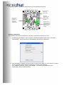
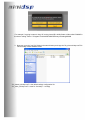
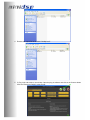
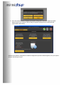
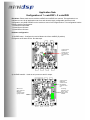
Application Note
Configuration of 1 x miniDSP + 2 x miniDIGI
Disclaimer: Please make sure to read the miniDIGI and miniDSP user manual. This application is not
intended as a one for all application note since each board is highly configurable. Note that in this
configuration, only ONE miniDIGI can be used as a source for the digital section. This configuration has the
following clocking configuration:
1 x miniDIGI as I2S master
1 x miniDIGI as I2S slave
1 x miniDSP as I2S slave
Hardware configuration
1) miniDSP board – Configured to receive Master clock from miniDIGI (S position)
Configured as I2S slave device. See last steps.
Jumper location
depends on
selected source.
See miniDIGI
manual for more
info.
2) miniDIGI board#1 – Used as an input source and for output.
Jumper location
depends on
selected source.
See miniDIGI
manual for more
info.
Make sure to
place miniDIGI in
Master by
removing jumper
typically located
here
I2S routing
depends on your
plug-in. Check
user manual of
miniDIGI.
3) miniDIGI board#2 – Used as an output device only and operating as I2S slave.
No jumper here to
make sure no
collision of data.
Place a jumper
here to put
miniDIGI in I2S
slave since
miniDIGI#1 is
already the I2S
I2S routing
depends on your
plug-in. Check
user manual of
miniDIGI.
Warning: Remove
that last jumper here
on this board only. It
basically remove the
MCLK from that
oscillator.
Software configuration
The miniDSP must first be configured as an I2S slave. See below instructions on how to.
1. Install the plug-in software on your computer. The Default installation path will be "C:\Program
Files\miniDSP". If a previous version was installed, make sure to un-install first.
2. Once installation completed, we need to create a unique folder called "90 + your board id” to ensure
that only this board will be configured as I2S slave in future synchronization
your_installation_path/your_plug-in_name/setting/".. You can find your board id from the
sychronization pop up window as follow.
For example, if my plug-in name is 2way-V5, and my board ID is 4848 Create a folder called "904848" in
the above "setting" folder. C:\Program Files\miniDSP\MiniDSP-2way-V5\setting\904848
3. Next step, go to the "conf_file" folder in the same directory and copy the "i2s_slave minidsp.conf" file
into the newly created "904848" folder
"i2s_master_minidsp.conf" is the default settings configuration file
"i2s_slave_minidsp.conf" is used for 2 minidsp + 1 minidigi.
4. Rename the copied file as the name "minidsp.conf".
5. 5, Plug in the usb cable to one minidsp. Open the plug-in software and click on the Connect button
Click the "Restore to Default" at the prompt.
6. Once the restore to default complete, go to system settings tab to select the "Digital input(I2S)"
Adjust values in the crossover, PEQ or delay as required. Unplug the usb to disconnect the
sychronization after setting.
Software and hardware configuration is finished. Simply stack up all three boards together, fire up the system
and you should be good to go!