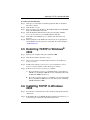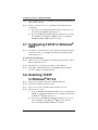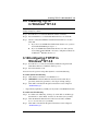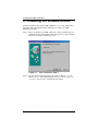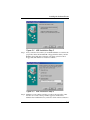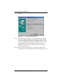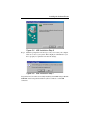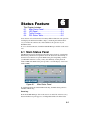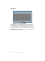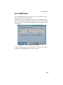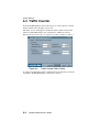
1
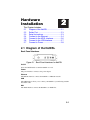
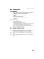
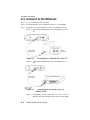
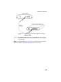
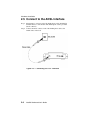
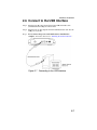
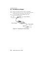
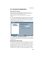
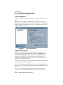
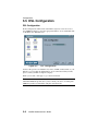
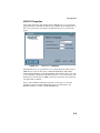
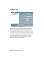
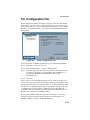
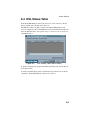
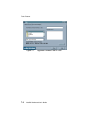
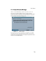
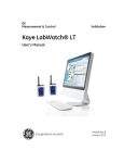
ARESCOM
NetDSL 800 ADSL
Modem
version 5.2b1
User’s Guide
Published April 2000
Copyright
© Copyright 1996, 1997, 1998, 1999, 2000 ARESCOM, Inc. All rights reserved.
No part of this documentation or software may be reproduced or distributed in
any form without prior written permission from ARESCOM, Inc.
ARESCOM, Inc. has the right to make revisions and to change the contents of
this document without any obligation to provide prior notice of such revisions
and changes.
ARESCOM, Inc. provides this documentation without any kind of warranty,
either expressed or implied, including but not limited to the implied warranties of
merchantability and fitness for a specific purpose. ARESCOM has the right to
make improvements or changes in the product(s) and/or software(s) described in
this documentation.
Address inquiries to:
ARESCOM, Inc.
3541 Gateway Blvd.
Fremont, California 94538
phone: (510) 445-3638
fax: (510) 445-3636
customer service: (510) 445-3638
e-mail: [email protected]
URL: http://www.arescom.com
Trademark
ARESCOM, ARESCOM NetDSL are trademarks of ARESCOM, Inc. Microsoft
and Windows 95/98 are registered trademarks of Microsoft Corporation. Pentium
is a registered trademark of Intel Corporation. All other trademarks and
registered trademarks belong to their respective companies.
Table of Contents
1.
Before You Begin
1.1
1.2
1.3
1.4
Hot Features ......................................................... 1-1
Package Includes ................................................. 1-1
Minimum System Requirements ........................ 1-2
Information You Will Need .................................. 1-2
2.
Hardware Installation
2.1
2.2
2.3
2.4
2.5
2.6
2.7
Diagram of the NetDSL ........................................ 2-1
Safety First ........................................................... 2-3
Setup Instructions ............................................... 2-3
Connect to the Ethernet ...................................... 2-4
Connect to the ADSL Interface ........................... 2-6
Connect to the USB Interface ............................. 2-7
Connect to Power ................................................ 2-8
3.
Software Installation
3.1
3.2
3.3
3.4
3.5
3.6
3.7
3.8
3.9
3.10
3.11
About TCP/IP ........................................................ 3-1
Detecting TCP/IP in Windows® 95/98 ................ 3-1
Installing TCP/IP in Windows® 95/98 ................. 3-2
Configuring TCP/IP in Windows® 95/98 ............ 3-2
Detecting TCP/IP in Windows® 2000 ................. 3-3
Installing TCP/IP in Windows 2000 ..................... 3-3
Configuring TCP/IP in Windows® 2000 ............. 3-4
Detecting TCP/IP in Windows® NT 4.0 .............. 3-4
Installing TCP/IP in Windows® NT 4.0 ............... 3-5
Configuring TCP/IP in Windows® NT 4.0 .......... 3-5
Installing the Software Drivers ........................... 3-6
4.
NetDSL Manager
4.1
4.2
Installing the NetDSL Software ........................... 4-1
Launching the NetDSL Manager ......................... 4-1
i
Table of Contents
5.
Configuration
5.1
5.2
5.3
5.4
5.5
5.6
Configuration ....................................................... 5-1
Outline of Configuration ...................................... 5-2
General Configuration ......................................... 5-3
LAN Configuration ............................................... 5-6
DSL Configuration ............................................... 5-8
Configuration File .............................................. 5-11
6.
Status Feature
6.1
6.2
6.3
6.4
Main Status Panel ................................................ 6-1
LED Panel ............................................................. 6-3
Traffic Counter ..................................................... 6-4
DSL Status Table ................................................. 6-5
7.
Tools Feature
7.1
7.2
Upgrade Firmware ............................................... 7-1
Reset Router/Bridge ............................................ 7-3
8.
Troubleshooting
8.1
8.2
8.3
Cannot Detect the Modem ................................... 8-1
Modem and PC are Not in the Same Subnet ..... 8-2
Cannot Upgrade the Firmware ............................ 8-2
Appendices
A.
B.
C.
D.
About Configuration Parameters .......................A-1
Ethernet Cable Pinout .........................................B-1
Warranty Information ...........................................C-1
Declaration of Conformity ...................................D-1
ii
NetDSL Software User’s Guide
Before You Begin
1
This Chapter Includes:
1.1
Hot Features........................................... 1-1
1.2
Package Includes ................................... 1-1
1.3
Minimum System Requirements............. 1-2
1.4
Information You Will Need ...................... 1-2
1.1 Hot Features
Bridge Packet Filtering Table
You can monitor and restrict the traffic flow through your NetDSL modem. This
is useful for protecting your network from undesired intrusion, and for
preventing selected local network traffic from exiting through the NetDSL.
NetDSL can be set to use up to 32 sequential criteria (filters) by which to check
each packet as it enters or leaves your network. Each filter can be set to check
source Mac packets, destination Mac packets, or both. You can also set each
packet to be passed, discarded, or passed to the next filter, depending on whether
or not a packet matches a filter.
Multiple PVC
The NetDSL supports up to 8 ATM PVC interfaces. In each interface, you have
the option to set the Virtual Path Identifier (VPI), Virtual Channel Identifier
(VCI), Unspecified Bit Rate (UBR), Constant Bit Rate (CBR), Peak Cell Rate
(PCR), and the Operations And Maintenance (OAM) F5 virtual channel timer.
1.2 Package Includes
• One NetDSL modem
• Power cord and adapter
• Get Started User’s Guide
• Software CD-ROM (contains Arescom Installation software, Software
User’s Guide, optional Web browser software, and third-party
applications/utilities)
• One RJ-11 to RJ-11 ADSL phone cable (7ft)
• One RJ-45 to RJ-45 straight Ethernet cable (7ft)
• One detachable USB cable
1-1
Minimum System Requirements
1.3 Minimum System Requirements
• ADSL line
• 10BaseT Ethernet or USB interface
• CD-ROM drive
NetDSL gives you the option of configuring the modem using the Arescom
NetDSL Manager. The system requirements for each are listed below:
Using the NetDSL Manager:
• Ethernet card
• PC* with at least a 486 microprocessor (Pentium® recommended)
• CD-ROM drive
• At least 4 MB of space available on the hard disk drive
• Microsoft® Windows® 95/98/2000 or Windows® NT 4.0 Operating
System
* You may configure the NetDSL from any PC attached to the Local
Area Network (LAN) with the requirements listed above.
1.4 Information You Will Need
To configure your modem, you will need to receive information from the remote
network to which you will connect, such as an Internet Service Provider (ISP) or
a company server. Consult the section below for a detailed list of information on
utilizing the Ethernet interface and the DSL interface. If you are unfamiliar with
any of the terms listed, refer to Appendix A, “About Configuration Parameters.”
The following information should be obtained from your ISP or company server.
• VPI
• VCI
• DSL line code
You MAY need the following information from your ISP or company server
based on your network setup:
• IP Address
• Subnet Mask
• Gateway IP Address
• PPP User name & Password
• DNS Address
1-2
NetDSL Software User’s Guide
Hardware
Installation
2
This Chapter Includes:
2.1
Diagram of the NetDSL .......................... 2-1
2.2
Safety First ............................................. 2-3
2.3
Setup Instructions................................... 2-3
2.4
Connect to the Ethernet.......................... 2-4
2.5
Connect to the ADSL Interface............... 2-6
2.6
Connect to the USB Interface................. 2-7
2.7
Connect to Power ................................... 2-8
2.1 Diagram of the NetDSL
Back Panel Interfaces
Figure 2.1 Back Panel Interfaces for NetDSL
On/Off
Select the On/Off switch to turn the NetDSL on or off.
Power
The power interface connects to the power adapter.
Ethernet
The Ethernet interface connects the NetDSL to a 10BaseT network.
USB
The USB interface allows you to connect your NetDSL to your PC using an USB
detachable cable.
DSL
The ADSL interface connects the NetDSL to an ADSL line.
2-1
Hardware Installation
Front Panel Interfaces
Figure 2.2 Front Panel Interfaces for NetDSL
PWR (Power)
A green LED is ON when power is supplied to the NetDSL.
DIAG (Diagnostic)
The yellow DIAG LED is an indicator that shows the NetDSL modem has been
successfully booted up and the software is functional. When NetDSL is powered
on, the DIAG LED flashes while the router is booting up. After 10 to 15 seconds,
the DIAG LED stops flashing and remains off.
LAN
The LAN LED displays the LAN connection between the modem and your
Ethernet network. The green LED remains solid while there is a connection to the
10BaseT system. The green LED flashes when data is being transmitted between
the modem and the Ethernet system.
USB
The USB LED displays the USB connection between the modem and your PC.
The yellow LED flashes slowly if the USB line is being trained. The yellow LED
remains solid if the USB line is trained and ready between the PC and the
modem. A flashing yellow LED indicates data activity between your PC and the
modem. If the data traffic is heavy, the frequency of the flashing yellow LED
becomes higher and will appear solid.
WAN LINK
Displays the connection between the modem and the remote DSL network. The
green LED flashes slowly if the DSL line is not connected or is being trained.
The green LED remains solid if the DSL line is trained and ready between the
modem and the remote switch.
WAN ACT (Activity)
A flashing yellow LED indicates data activity between the DSL network and the
modem. If the data traffic is heavy, the frequency of the flashing yellow LED
becomes higher and will appear to be solid.
2-2
NetDSL Software User’s Guide
Hardware Installation
2.2 Safety First
Personal Safety
• In case of emergency, locate the closest electricity power-off switch.
• Refrain from touching any active wires or terminals.
• Remove jewelry before working on equipment connected to
electricity.
• Keep cables away from walkways.
• Dispose of this product in accordance with national laws and
regulations.
Product Handling
• Keep ventilation slots clear.
• Operate in a clean and dust-free location.
• Cables must be attached to the correct interfaces; to do otherwise may
result in damaging the modem or produce hazardous voltage.
• Do not operate or store the product in an environment that surpasses
temperature or humidity specifications.
2.3 Setup Instructions
Step 1. Choose a location for the NetDSL close to a power outlet and a
telephone line outlet. Preferably select a convenient location that does
not experience too much foot traffic and is away from sunlight.
Step 2. Choose a level surface for the NetDSL – such as a desk top, shelf, or
table.
Step 3. Place the NetDSL on the predetermined surface, so you can see the back
panel.
2-3
Hardware Installation
2.4 Connect to the Ethernet
Step 1. Locate your Ethernet cable (included).
Step 2. Attach the Ethernet cable to the Ethernet interface of your NetDSL.
Step 3. Plug in the loose end of the Ethernet cable to your Ethernet network.
Option 1. Attach the included Ethernet cable to the Ethernet port on a
PC.
Figure 2.3
Connecting to a Ethernet Port on a PC
Option 2. Attach the included Ethernet cable to the uplink port on a
hub.
Figure 2.4
Connecting to the Uplink Port on a
Network Hub
Option 3. If the uplink port is unavailable, then you can use a crossover
Ethernet cable (Not included) and attach it to the non-uplink
2-4
NetDSL Software User’s Guide
Hardware Installation
ports on a hub.
Figure 2.5 Connecting to the Non-Uplink Port on a
Network Hub
Step 4. The LAN LINK LED on the front panel should be lit green to indicate a
valid Ethernet connection. If the LAN LINK LED is not lit, then repeat
steps 1 through 3.
Note: See Appendix B Ethernet Cable Pinout for further information about the
differences between a straight-through cable and a crossover cable.
2-5
Hardware Installation
2.5 Connect to the ADSL Interface
Step 1. Plug the RJ-11 connector end of the ADSL phone cable (included) in
the DSL interface of the modem. The ADSL phone cable is provided
(RJ-11 to RJ-45).
Step 2. Connect the RJ-45 connector end of the ADSL phone cable to the
ADSL outlet on the wall.
Figure 2.6 Connecting the DSL Interface
2-6
NetDSL Software User’s Guide
Hardware Installation
2.6 Connect to the USB Interface
Step 1. Plug the Type-B (square-shaped) end of the USB detachable cable
(included) into the USB port of the modem.
Step 2. Plug the Type-A (flat-shaped) end of the USB detachable cable into the
USB port of your PC.
Step 3. Do not turn on the power switch until software installation is
complete. Proceed to Section 3.11 “Installing the Software Drivers.”
Figure 2.7 Connecting to the USB Interface
2-7
Hardware Installation
2.7 Connect to Power
Step 1. Plug the power adapter in the Power interface of the NetDSL.
Step 2. Connect one end of the power cord to the power adapter, and insert the
other end of the power cord to the power outlet on the wall.
Step 3. To activate the NetDSL, turn the ON/OFF switch to ON.
Figure 2.8 Connecting to a Power Supply
2-8
NetDSL Software User’s Guide
Software
Installation
f
3
This Chapter Includes:
3.1
About TCP/IP.......................................... 3-1
3.2
Detecting TCP/IP in Windows® 95/98.... 3-1
3.3
Installing TCP/IP in Windows® 95/98..... 3-2
3.4
Configuring TCP/IP in Windows® 95/98 3-2
3.5
Detecting TCP/IP in Windows® 2000..... 3-3
3.6
Installing TCP/IP in Windows 2000 ........ 3-3
3.7
Configuring TCP/IP in Windows® 2000 . 3-4
3.8
Detecting TCP/IP in Windows® NT 4.0 .. 3-4
3.9
Installing TCP/IP in Windows® NT 4.0... 3-5
3.10 Configuring TCP/IP in Windows® NT 4.03-5
3.11 Installing the Software Drivers................ 3-6
3.1 About TCP/IP
To gain high-speed and shared access to the Wide Area Network (WAN), your
Local Area Network (LAN) needs to be configured for the modem. Each network
node on your LAN must install a network protocol so that they can communicate
with the modem. The modem requires the TCP/IP network protocol. The TCP/IP
Properties window in Windows® 95/98/2000 or NT 4.0 connects the node’s
Ethernet information to the network’s protocol data. Make sure that each network
node on your LAN has TCP/IP available. To ensure smooth setup, you must
install the TCP/IP network protocol on the PCs before you install the modem.
Note: We have already configured your NetDSL prior to shipping. The NetDSL
is configured with the default IP address of 192.168.1.1 and subnet mask of
255.255.255.0.
3.2 Detecting TCP/IP in
Windows® 95/98
Step 1. Turn on your computer and start Windows® 95/98.
Step 2. Click the Start button and then select Settings.
Step 3. Choose Control Panel and double click Network icon.
Step 4. Click the Configuration tab.
3-1
Installing TCP/IP in Windows® 95/98
A. If you see TCP/IP listed under Network Components, you already
have TCP/IP on your Windows® 95/98. Proceed to configuration
directions for Windows® 95/98 in Section 3.4.
B. If you do not see TCP/IP listed under Network Components, you do
not have TCP/IP on your Windows® 95/98. Proceed to the next
section, “Installing TCP/IP in Windows® 95/98.”
3.3 Installing TCP/IP in
Windows® 95/98
Step 1. From the Configuration tab in the Network window, click Add.
Step 2. Select Protocol for the type of network component, and click Add.
Step 3. Choose Microsoft for Manufacturers list box and TCP/IP for Network
Protocols list box, then click OK.
Step 4. Check to see TCP/IP is listed under Network Components.
A. If you do not see TCP/IP listed under Network Components, you
have not installed TCP/IP. Repeat Steps 1 - 4.
B. If you see TCP/IP listed under Network Components, you already
have TCP/IP on your Windows® 95/98. Proceed to configuration
directions for Windows® 95/98 in Section 3.4.
3.4 Configuring TCP/IP
in Windows® 95/98
Step 1. From the Configuration tab, select TCP/IP (for Ethernet adapters) listed
under Network Components and then click Properties.
Step 2. Select the IP Address tab.
You now have the option of using either dynamic or static IP addressing.
To enable dynamic IP addressing
Step 1. Click Obtain an IP Address automatically.
Step 2. OPTIONAL* Click the DNS Configuration tab and select Disable
DNS. If you previously entered any parameters, clear all pre-existing
settings.
Step 3. Select the Gateway tab and then click Remove to clear all pre-existing
settings.
Step 4. Click OK to exit TCP/IP Properties window and click OK to exit
Network window. When prompted, restart Windows® 95/98. If you are
not prompted to restart Windows® 95/98, do so manually. Proceed to
Chapter 4, “NetDSL Manager.”
* If specifically required by your ISP, you may need to enter DNS
information.
3-2
NetDSL Software User’s Guide
Detecting TCP/IP in Windows® 2000
To enable static IP addressing
Step 1. Click Specify an IP Address and then type the IP Address and Subnet
Mask (for your PC).
Step 2. Click the Gateway tab.
Step 3. Type in your Gateway IP Address (the LAN IP address for the NetDSL)
from your ISP and then click Add.
Step 4. Click the DNS tab. Enter the Host name, Domain name, and DNS
Service Search Order (for your LAN) and then click Add.
Step 5. Click OK to exit TCP/IP Properties window and click OK to exit
Network.
Step 6. When prompted, restart Windows® 95/98. If you are not prompted to
restart Windows® 95/98, please do so manually. Proceed to Chapter 4,
“NetDSL Manager.”
3.5 Detecting TCP/IP in Windows®
2000
Step 1. Turn on your computer and log-in to Windows 2000.
Step 2. Click the Start button and select Settings.
Step 3. Choose Control Panel, and then double click Network and Dial-up
Connections icon
Step 4. Double click on the Local Area Connection icon. In the Local Area
Connection Status window, click on the Properties button.
Step 5. In the Local Area Connection Properties window:
A. If you see the Internet Protocol (TCP/IP) listed, you already have
TCP/IP on your Windows 2000. Proceed to configuration directions
for Windows 2000 in Section 3.6.
B. If you do not see Internet Protocol (TCP/IP), you do not have TCP/
IP on your Windows 2000. Proceed to the next section, “Installing
TCP/IP in Windows 2000.”
3.6 Installing TCP/IP in Windows
2000
Step 1. From the General tab in the Local Area Connection Properties window,
click Install.
Step 2. In the Internet Protocol (TCP/IP) Properties window, select the Protocol
icon for the type of network component and click Add.
Software Installation
3-3
Configuring TCP/IP in Windows® 2000
Step 3. Choose the Internet Protocol (TCP/IP) icon from the Network Protocol
list box, then click OK.
Step 4. Check to see if Internet Protocol (TCP/IP) is listed under Network
Components.
A. If you do not see TCP/IP listed under Network Components, you
have not installed TCP/IP. Repeat steps 1 - 4.
B. If you see TCP/IP listed under Network Components, you already
have TCP/IP on your Windows 2000. Proceed to “Configuring
TCP/IP in Windows 2000” in the next section.
3.7 Configuring TCP/IP in Windows®
2000
Step 1. From the General tab in the Local Area Connection Properties window,
select Internet Protocol (TCP/IP) listed under Network Components
and click Properties.
To enable static IP addressing:
Step 1. Click Use the following IP Address and then type the IP Address, Subnet
Mask, and Default gateway.
Step 2. Enter the Preferred and Alternate DNS server IP addresses.
Step 3. Click OK to exit the Internet Protocol (TCP/IP) Properties window.
Proceed to Chapter 4 “NetDSL Manager.”
3.8 Detecting TCP/IP
in Windows® NT 4.0
Step 1. Turn on your computer and log-in to Windows® NT 4.0.
Step 2. Click the Start button and select Settings.
Step 3. Choose Control Panel, and then double click Network icon.
Step 4. Click the Protocols tab.
A. If you see TCP/IP listed under Network Protocols, you already have
TCP/IP on your Windows® NT. Proceed to configuration directions
for Windows® NT 4.0 in Section 3.7.
B. If you do not see TCP/IP listed under Network Protocols, you do
not have TCP/IP on your Windows® NT. Proceed to the next
section, “Installing TCP/IP in Windows® NT 4.0.”
3-4
NetDSL Software User’s Guide
Installing TCP/IP in Windows® NT 4.0
3.9 Installing TCP/IP
in Windows® NT 4.0
Note: Consult your Network Administrator if you do not have authorization to
change settings for your PC.
Step 1. From the Protocols tab in the Network window, click Add.
Step 2. Select TCP/IP Protocol listed under Network Protocols, Click OK.
Step 3. Check to verify that TCP/IP is listed under Network Protocols, then
Click OK.
A. If you do not see TCP/IP listed under Network Protocols, you have
not installed TCP/IP. Repeat steps 1 - 3.
B. If you see TCP/IP listed under Network Protocols, then you have
successfully installed TCP/IP. Proceed to configuration directions
for Windows® NT 4.0 in Section 3.7.
3.10Configuring TCP/IP in
Windows® NT 4.0
Step 1. From the Protocols tab, select TCP/IP (for Ethernet adapters) listed
under Network Protocol and then click Properties.
Step 2. Select the IP Address tab.
You now have the option of using either dynamic or static IP addressing.
To enable dynamic IP addressing
Step 1. Click Obtain an IP Address from DHCP Server.
Step 2. OPTIONAL* Click the DNS tab and select Disable DNS. If you
previously entered any parameters, clear all pre-existing settings.*
Step 3. Click OK to exit Network Properties window. Proceed to Chapter 4
“NetDSL Manager.”
*
If specifically required by your ISP, you may need to enter DNS information.
To enable static IP addressing
Step 1. To enable static addressing, click Specify an IP Address and then type
the IP Address, Subnet Mask, and Gateway IP Address(for your PC).
Step 2. Click the DNS tab. Enter the Host name, Domain name, and DNS
Service Search Order (for your LAN).
Step 3. Click OK to exit Network Properties window. Proceed to Chapter 4
“NetDSL Manager.”
Software Installation
3-5
Installing the Software Drivers
3.11 Installing the Software Drivers
Your PC should have detected the USB to Ethernet as soon as the USB cable is
plugged in. The following instructions will help you complete the USB
installation procedure.
Step 1. After your PC detects an USB connection, a message window appears
to indicate that the software driver installation process is about to begin.
Click Next to start the installation process.
Figure 3.1 USB Installation Step 1
Step 2. The next message window prompts the question “What do you want
Windows to do?” Select the first option “Search for the best driver for
your device. (Recommend)” and click the Next button.
3-6
NetDSL Software User’s Guide
Installing the Software Drivers
Figure 3.2 USB Installation Step 2
Step 3. Now you need to select where you would like Windows to search for the
proper files. Insert the included CD or floppy disk into either your CDROM or floppy disk drive. Select the appropriate options for CD or
floppy disk, and click the Next button to continue.
Figure 3.3 USB Installation Step 3
Step 4. Windows is now reading your CD to search for the proper files. Once
the files are located, a message window appears to indicate that
Windows has found the files for your device. Click on the Next button to
Software Installation
3-7
Installing the Software Drivers
continue.
Figure 3.4 USB Installation Step 4
Step 5. After Windows has installed the software driver files from the CD, it
will need to install some files from your Windows 98 CD to complete
the software driver installation. A message window appears to ask you
to insert your Windows 98 CD. Insert your Windows 98 CD into your
CD-ROM drive and click OK. If Windows wants the path to your
Windows 98 CD, enter the path to the proper drive and click OK to
complete the installation.
Step 6. The next message window appears to show that the software driver
installation process is now complete. Click the Finish button to proceed.
3-8
NetDSL Software User’s Guide
Installing the Software Drivers
Figure 3.5 USB Installation Step 6
Step 7. Windows prompts the next message to ask you to restart your computer.
Click Yes to reboot your system. This is highly recommended for your
PC to properly recognize the new network settings.
Figure 3.6 USB Installation Step 7
Congratulations!!! You have successfully installed your NetDSL using USB. The
USB LED on the front panel should be lit yellow to indicate a valid USB
connection.
Software Installation
3-9
Installing the Software Drivers
3-10
NetDSL Software User’s Guide
NetDSL Manager
4
This Chapter Includes:
4.1
Installing the NetDSL Software............... 4-1
4.2
Launching the NetDSL Manager ............ 4-1
The NetDSL Manager gives you access to the configuration and administrative
controls for the NetDSL. Install the NetDSL software on PCs that you want to
give access to these controls. If you have difficulties configuring your NetDSL,
consult Chapter 8 “Troubleshooting,” or the help menu in the NetDSL Manager,
or refer to the FAQs located on ARESCOM’s website (http://
www.arescom.com).
Note: You must install the TCP/IP network protocol on the PCs before you
install the NetDSL Manager. For more information on installing and configuring
TCP/IP refer to the instructions in the previous chapter.
4.1 Installing the NetDSL Software
Step 1. Start Windows® 95/98 or Windows® NT 4.0.
Step 2. Insert the included ARESCOM CD into your CD-ROM drive
Step 3. Click Start, then choose Run.
Step 4. Click the Browse button, and look in your CD-ROM drive.
Step 5. Select the ARESCOM folder, and then the NetDSL Manager folder.
Step 6. Select the setup.exe file and click the Open button.
Step 7. Click the OK button.
4.2 Launching the NetDSL M anager
When you launch the NetDSL Manager, you will be presented with a sequence of
panels that help you decide which modem you want to manage, and how to
manage it. The sequence of panels is as follows:
1. Multiple Routers/Bridges Selection— provides the number of
and basic information about all Arescom modems that the software
has detected on your LAN.
2. NetDSL Manager— is the main software that allows you to
configure, maintain and monitor your selected modem.
4-1
NetDSL Manager
For further information on the available features, refer to the NetDSL Manager
Overview later in this section.
Note: After the initial modem configuration, you can reset the modem
configuration parameters at any time from the Tools feature. Just select the Reset
Router/Mode tab, click on the “Delete Configurations and Reset to Manufacturer
Mode” box, and then click Reset Router.
Multiple Routers/Bridges Selection Window
When you run the NetDSL Manager program the Multiple Routers/Bridges
Selection window will appear. The program is searching for the NetDSL modems
attached to the same network as your PC. This procedure may take a few
seconds.
Figure 4.1
Multiple Routers/Bridges Selection
After a few seconds, the NetDSL Manager will display a message indicating that
it has found one or more modems on your local network. The window lists all
detected modems, both configured and unconfigured. From this list you can
select the specific modem that you wish to configure or re-configure.
If the modem is not in the same subnet as the managing PC, a Subnet window
appears and allows you to choose three selections. You can Change the router’s
IP address and keep the other configuration, Reset the router to Manufacture
mode and delete the configuration, or Change your computer’s TCP/IP settings.
After you have made you choice, click Next to proceed.
4-2
NetDSL Software User’s Guide
NetDSL Manager
Figure 4.2
Subnet window
If the NetDSL Manager is unable to detect the modem or it gives you an error
message, consult the on-line help menu for more detailed instructions.
To continue, select a modem and click Enter. You will automatically enter the
NetDSL Manager. From the NetDSL Manager you can use any one of the
following features:
• Configuration to get your modem up and running.
• Status to monitor many of your modem’s operations.
• Tools offers some basic utilities for maintenance of your modem.
4-3
NetDSL Manager
NetDSL Manager Overview
The NetDSL Manager gives you access to all of the features of the NetDSL. To
activate a feature, you may use the keyboard by following table below. Note that
both lower and uppercase letters may be used. The letters to be used with the Alt
key to activate the Configuration, Status, and Tools figure are underlined in the
NetDSL Manager. Alternatively, you may select the feature using your mouse
pointer. When the feature button is selected, the mouse pointer changes into a
hand. Once you select a feature, click on the feature button.
Figure 4.3
Table4.1
NetDSL Manager
NetDSL
Feature
Keyboard
Keys
Configuration
Alt f
Status
Alt s
Tools
Alt t
Help
F1
Exit
Alt F4
Keyboard Keys to Activate NetDSL Features
The NetDSL Manager gives you access to the following features:
• Configuration—a step-by-step guide to configuring all parameters
of your modem: General Configuration, LAN Configuration, DSL
Configuration, and Configuration File settings.
4-4
NetDSL Software User’s Guide
NetDSL Manager
• Status—allows you to remotely monitor many of the modem’s
functions, such as Front Panel LED operation, the Traffic Counter, and
the DSL Status Table.
• Tools.—provides you with some tools for performing some basic
modem maintenance tasks, firmware upgrades, and resetting the
modem.
4-5
NetDSL Manager
4-6
NetDSL Software User’s Guide
Configuration
5
This Chapter Includes:
5.1
Configuration .......................................... 5-1
5.2
Outline of Configuration.......................... 5-2
5.3
General Configuration ............................ 5-3
5.4
LAN Configuration .................................. 5-6
5.5
DSL Configuration .................................. 5-8
5.6
Configuration File ..................................5-11
5.1 Configuration
The NetDSL Configuration walks you through the configuration of the NetDSL
with a series of windows. You will be asked to enter information that you
received from your ISP or network administrator – refer to Section 1.4,
Information You Will Need for the configuration parameters for a Single IP
Address Account or a Multiple IP Address Account, and other additional
parameters necessary for use of the unit.
For your convenience, the NetDSL Configuration provides instructions in each
window to guide you through the installation process. To exit the NetDSL
Configuration, click on the Exit button. If you need more information, click on
the Help button.
5-1
Configuration
5.2 Outline of Configuration
With the Configuration feature you have the flexibility to configure one
parameter at any time and to change more technical default settings. The
Configuration window is organized in a hierarchical tree format. From the
NetDSL Manager, click General Configuration to access the General
Configuration window. Click on the item that you wish to configure, and then set
the parameters.
General Configuration
• Administrative Security: Sets your modem’s name and enables
password protection (optional).
• Bridge Packet Filtering Table:Monitors and selectively filters
packets that enter or leave the NetDSL.
LAN Configuration
• LAN Configuration: Allows you to set the primary and secondary IP
addresses and Subnet Mask information for the LAN.
DSL Configuration
• ATM PVC Properties: Allows you to specify the name of the ATM
Permanent Virtual Circuit (PVC), and the values of Virtual Path
Identifier (VPI) and Virtual Channel Identifier (VCI).
• ATM Service Type: Allows you to choose the ATM service category
supporting your ATM connection and the rate parameters associated
with the service: Unspecified Bit Rate (UBR) and Constant Bit Rate
(CBR). From this panel you can specify the Peak Cell Rate (PCR) in
kbps, and you can set the Operations and Maintenance (OAM) F5
timer period. If the period is set to zero, the OAM F5 loopback cell
will not be sent. If the period is non-zero, the loopback cell is sent
according to the specified period to the remote peer.
Configuration File
• Save Configuration File: Saves your customized configuration
settings to your local hard disk drive as a configuration file (*.cfg).
This is especially helpful for network management.
• Load Configuration File: Allows you to load any previously saved
configuration file.
5-2
NetDSL Software User’s Guide
Configuration
5.3 General Configuration
Administrative Security
The first configuration panel in the NetDSL General Configuration is the
Administrative Security. From this panel, you can create a Router Name and
select Password Protected for administrative security.
Naming your modem is mandatory. The default name for the modem is
“NetDSL.”
If you are concerned with administration security, you should select Password
Protected. This optional feature limits NetDSL Manager access to users with the
correct password. To select this feature, check Password Protected, and then
click Change Password. When you type your password and confirmation in the
edit boxes, they will appear as asterisk (****).
Figure 5.1
Administrative Security
After setting your Administrative Security, Click Apply to continue configuring
your modem. To exit the NetDSL, click on the Exit button. If you need help, click
on the Help button.
Bridge Packet Filtering Table
From Configuration, double-click on the General Configuration icon, and click
on the Bridge Packet Filtering Table in the left panel. The bridge packet filters
also allow you to monitor and selectively filter packets that enter or leave the
NetDSL when in the bridge mode. You can use filtering to protect your network
from unauthorized access, and restrict certain traffic from leaving your LAN.
The Bridge Packet Filtering Table also allows up to 32 sequential filters, and
each filter can be set to examine source MAC, destination MAC, or both. From
5-3
Configuration
this panel, you can Add New Bridge Packet Filter, Modify Bridge Packet Filter,
or Remove Bridge Packet Filter.
Figure 5.2
Bridge Packet Filter
Add New Bridge Packet Filter
To add a new IP Packet Filter, click the New button. This will open the Add New
Bridge Packet Filter window.
Figure 5.3
Add New Bridge Packet Filter
Enter the Bridge packet filter parameters according to the following criteria:
MAC:
Identifies each device on the network and the Internet.
The characteristics of each packet that enters the NetDSL are compared to the
bridge packet filters’ parameters to see if they match (true), or whether they do
not match (false).
For either true/false condition, the packets can be set to:
5-4
Pass:
Automatically pass through the modem.
Restrict:
Pass only if there is an available connection.
NetDSL Software User’s Guide
Configuration
Discard:
Packet is blocked and discarded.
Pass to next filter:
Packet goes to the next filter in sequence.
When you are finished, click OK. If you do not want to create an bridge packet
filter, click Cancel to close the Add New Bridge Packet Filter window.
Modify Bridge Packet Filter
If you want to change the parameters of an bridge packet filter, select the filter
number, and then click Modify. This will open the Modify Bridge Packet Filter
window. You can change any of the parameters or settings. When you are
finished, click OK. If you do not want to modify this filter, click Cancel to close
the Modify Bridge Packet Filter window.
Remove Bridge Packet Filter
To delete a filter, select the filter number, and then click Remove. Click Yes to
remove the selected filter or click No to keep it.
Once you have finished setting these parameters, click Apply to review the
parameters you have entered and then click Finish to send settings to the
NetDSL. Click Exit to return to the NetDSL Manager.
5-5
Configuration
5.4 LAN Configuration
LAN Configuration
From Configuration, use the list in the left panel to open the LAN Configuration
menu.
LAN Configuration assigns the IP address of the modem on your LAN, and
defines the range of IP addresses that the modem can locally access from that IP
Address (its subnet). The LAN Interface can be configured for either a single or
multiple IP address account.
Figure 5.4
LAN Configuration
Single IP Address Account
Selecting Use Default IP Address and Subnet Mask enables your modem to
automatically assign itself a default Private IP Address of 192.168.1.1 with a
Subnet Mask of 255.255.255.0. This will give you an available range of IP
addresses from 192.168.1.2 to 192.168.1.254 that can be assigned to your
network devices. The IP Address and Subnet Mask will be grayed out since you
do not need to enter this information.
You can also opt to de-select Use Default IP Address and Subnet Mask and enter
your own IP Address and Subnet Mask.
If you have an additional subnet in your network you would like the modem to be
able to access, you may provide its IP Address and Subnet Mask under Secondary
IP Address.
Once you have finished setting these parameters, click Apply to review the
parameters you have entered and then click Finish to send settings to the
5-6
NetDSL Software User’s Guide
Configuration
NetDSL. Click Exit to return to the NetDSL Manager.
5-7
Configuration
5.5 DSL Configuration
DSL Configuration
From Configuration, double-click on the DSL Configuration icon. To create a
new ATM PVC interface, select the appropriate DSL line mode and double-click
on the Make New ATM PVC icon.
Figure 5.5
DSL Configuration
You have the option to use ANSI T1.413, G.Lite, G.DMT, or Multi Mode as your
DSL line mode. To find out which DSL line mode works better with your unit,
please consult your ISP or telephone company.
When you are done, click Apply to go to the next window.
Note: The DSL line mode refers to the entire NetDSL unit and not each
individual ATM PVC profile. Once you have made your choice, all subsequent
ATM PVC profiles created will be using the same line mode.
5-8
NetDSL Software User’s Guide
Configuration
ATM PVC Properties
After typing in the name and clicking OK, the ATM PVC Properties panel will
appear. Note that a maximum of 8 PVCs may be defined. If you double-click on
the icon of a previously created PVC, the ATM PVC Properties panel will also
appear.
Figure 5.6
ATM PVC Properties
The ATM PVC Properties panel allows you to change the name of the selected
ATM interface and to set the values of Virtual Path Identifier (VPI) and the
Virtual Channel Identifier (VCI). The minimum and maximum values of the VCI
are 32 and 4,095, respectively. VCI values from zero to 31 are reserved for wellknown protocols. Note that two ATM connections can have the same VCI value
only if the VPIs are distinct.
Once you have finished setting these parameters, click Apply to review the
parameters you have entered and then click Finish to send settings to the
NetDSL. Click Exit to return to the NetDSL Manager.
5-9
Configuration
ATM Service Type
Click on ATM Service Type in the left panel.
Figure 5.7
ATM Service Type
This panel allows you to select the ATM Service Type for the ATM interface.
Presently, Unspecified Bit Rate (UBR) and Constant Bit Rate (CBR) are
available. You can specify the Peak Cell Rate (PCR) in kbps. This panel also
allows you to specify the period for the Operations And Maintenance (OAM) F5
(virtual channel) timer. If the period is set to zero, the OAM F5 loopback cell is
not sent. If the period is set to a non-zero value, the loopback cell is transmitted
to the remote peer according to the specified period. Note that the local peer will
always respond to a loopback cell that is transmitted by the remote peer.
Once you have finished setting these parameters, click Apply to review the
parameters you have entered and then click Finish to send settings to the
NetDSL. Click Exit to return to the NetDSL Manager.
5-10
NetDSL Software User’s Guide
Configuration
5.6 Configuration File
From Configuration, double-click on the Configuration File icon, then doubleclick on the Configuration File to open the menu. The Save Configuration File
feature allows you to save your custom configuration settings to your local hard
disk drive as a configuration file (*.cfg). This is especially helpful for network
management.
Figure 5.8
Save Configuration File
To keep the current configuration setting that you just entered in the NetDSL:
Step 1. Click Save Configuration File As....
Step 2. Enter the File Name for your new configuration file.
Step 3. Select the appropriate drive, directory, and file folder to indicate where
you want to save the file on your hard drive. The default path is “c:/
Program Files/NetDSL/” and the default file name is “My
Configuration.cfg.”
Step 4. Click Save.
Once you have a saved Configuration Profile you can load it at any time. Just
click Load Configuration Profile and click the Load Configuration button. Select
the appropriate drive, directory, and file folder to locate the configuration profile
file. Choose the configuration profile file (*.cfg) and then click Open. Click Yes
to confirm that you want to load the configuration profile. Click OK at the
confirmation that the configuration profile has been successfully loaded to the
NetDSL. You will return to the NetDSL window.
Once you have finished setting these parameters, click Apply to review the
parameters you have entered and then click Finish to send settings to the
NetDSL. Click Exit to return to the NetDSL Manager.
5-11
Configuration
5-12
NetDSL Software User’s Guide
Status Feature
6
This Chapter Includes:
6.1
Main Status Panel .................................. 6-1
6.2
LED Panel .............................................. 6-3
6.3
Traffic Counter ........................................ 6-4
6.4
DSL Status Table.................................... 6-5
Status feature collects information from many different functions and operations
and displays the information within a single, convenient panel. This makes it
easy to monitor the current status, and troubleshoot the operation of your
NetDSL modem.
To access the Status Feature, launch the NetDSL Manager and click on the Status
icon.
6.1 Main Status Panel
The Main Status panel is the default panel when Status feature is opened. If the
Main Status panel has been expanded to show the Status tabs, then clicking on
the Hide Details button can open the Main Status panel. Depending on where
your NetDSL modem is located, you may have difficulty viewing the front
window LEDs. The Main Status panel provides a real-time display of the front
window LEDs.
Figure 6.1
Main Status Panel
To supplement the front window LED monitoring, the Main Status panel also
includes an Event Log.
Event Log
From the NetDSL Manager click on the Status icon and click on the Event Log
button. The Event log will appear as an independent window from the Status
6-1
Status Feature
window.
Figure 6.2
Event Log in Status
The Event Log helps you pinpoint the date and time a connectivity problem
occurred. Every time you close Status the Event Log will reset. If you want to
save the contents of the log you may do so by clicking on the Save Event Log
button and saving the file to your computer’s hard drive or to a 3.5” floppy disk.
To close the Event Log, click the Close button. To exit Status and return to the
NetDSL Manager, click the Close button.
6-2
NetDSL Software User’s Guide
Status Feature
6.2 LED Panel
From the NetDSL Manager click on the Status icon, click on the Show Details
button, and then select the LED Panel tab.
Depending on where your modem is located, you may have difficulty viewing
the front window LEDs of the NetDSL. The LED Panel tab provides a real-time
display of the front window LEDs and the DSL Line Upstream and Downstream
speeds in Kbps.
Figure 6.3
LED Panel Tab in Status
To return to the Main Status panel, click the Hide Details button. To exit Status
and return to the NetDSL Manager, click the Close button.
6-3
Status Feature
6.3 Traffic Counter
From the NetDSL Manager click on the Status icon, click on the Show Details
button, and then select the Traffic Counter tab.
The Traffic Counter tab displays real-time data traffic counters for the LAN
interface and the DSL interface. For each interface, cumulative totals are
displayed for Sent Packets, Received Packets, Sent Bytes, and Received Bytes.
Figure 6.4
Traffic Counter Tab in Status
To return to the Main Status panel, click the Hide Details button. To exit Status
and return to the NetDSL Manager, click the Close button.
6-4
NetDSL Software User’s Guide
Status Feature
6.4 DSL Status Table
From the NetDSL Manager click on the Status icon, click on the Show Details
button, and then select the DSL Status Table tab.
The DSL Status Table tab displays all the user-defined ATM interfaces and
protocol configuration. For each ATM interface listed, the DSL Status Table will
show the ATM PVC Name, Encapsulation Type, Sent Packets, Received Packets,
and NAT IP address.
Figure 6.5
DSL Status Table Tab in Status
To update and display the changes in the DSL Status Table tab, click the Refresh
Status Table button.
To return to the Main Status panel, click the Hide Details button. To exit Status
and return to the NetDSL Manager, click the Close button
6-5
Status Feature
6-6
NetDSL Software User’s Guide
Tools Feature
7
This Chapter Includes:
7.1
Upgrade Firmware.................................. 7-1
7.2
Reset Router/Bridge ............................... 7-3
The NetDSL Manager provides you with some tools for performing basic modem
maintenance tasks, such as firmware upgrades and resetting the modem.
To access the Tools Feature, launch the NetDSL Manager and click on the Tools
icon.
7.1 Upgrade Firmware
Click Tools in the NetDSL Manager, and then select the Upgrade Firmware tab.
You can download firmware upgrades to the NetDSL using the Upgrade
Firmware feature. You can obtain upgrade firmware files from ARESCOM’s
web site. You can save the binary firmware file on a floppy of your hard drive.
Once you receive your firmware file:
Step 1. Insert the diskette in your floppy disk drive or download the file to your
hard disk drive.
Step 2. From the Upgrade Firmware panel, select the appropriate drive,
directory, and file folder to locate the firmware file.
Choose the firmware file (*.bin) and then click Upgrade.
Make sure you are downloading the CORRECT NetDSL firmware file.
Upgrading the NetDSL with the incorrect file may cause damage to the NetDSL.
7-1
Tools Feature
Figure 7.1
7-2
Upgrade Firmware Tab in Tools
NetDSL Software User’s Guide
Tools Feature
7.2 Reset Router/Bridge
Click Tools in the NetDSL Manager, and then select the Reset Router tab.
You can reset your modem from the Reset Router tab. Select the Delete
Configurations and Reset to Manufacture Mode checkbox if you want to remove
all your custom settings while resetting your modem. Otherwise, if you do not
select the checkbox, the modem will simply reboot.
Figure 7.2
Reset Router
If you have deleted your custom configuration, you will need to re-configure
your modem after it reboots. Remember, internet working connectivity is not
possible with an unconfigured modem. To reconfigure your parameters, return to
Configuration in the NetDSL Manager.
7-3
Tools Feature
7-4
NetDSL Software User’s Guide
Troubleshooting
8
This Chapter Includes:
8.1
Cannot Detect the Modem...................... 8-1
8.2
Modem and PC are Not in the
Same Subnet.......................................... 8-2
8.3
Cannot Upgrade the Firmware ............... 8-2
If you can not find the answers to your problems here, consult the help menu in
the NetDSL Manager or refer to the FAQs located on -ARESCOM’s website
(http://www.arescom.com).
8.1
1.
Cannot Detect the Modem
Verify that your modem is connected to your Ethernet LAN.
• Please check and see if the power adapter and cord are connected
properly to the NetDSL. Make sure you switch the power switch to
ON.
• If you are connecting your NetDSL to an Ethernet network hub, use a
straight-through Ethernet cable, and make sure you are connecting to
the uplink port of the hub. If an uplink port is unavailable, use a crossover Ethernet cable and connect it to a non-uplink port.
• If you are connecting your NetDSL to an Ethernet network PC, then
use a straight-through Ethernet cable.
Note: See Appendix B “Ethernet Cable Pinout” for further information
about the differences between a straight-through and a crossover Ethernet
cable.
Another way you can confirm that there is a physical connection to your
LAN is by checking the LED located on the front panel of the NetDSL
modem. The LAN Link LED of will lit green to indicate a valid LAN
connection. If the LAN Link LED of is not green, then check the connection
between the modem and your LAN. Re-start the NetDSL Manager to see if it
can detect the modem.
3.
Please select “Specify an IP Address” in TCP/IP Properties for Windows 95/
98 or Windows NT 4.0. Set your IP Address to a value between 192.168.1.2
and 192.168.1.254, the Subnet Mask to 255.255.255.0, and the Gateway as
192.168.1.1. When prompted, restart your computer otherwise do so
manually. Re-start NetDSL Manager to see if it can detect the modem.
8-1
Modem and PC are Not in the Same Subnet
8.2 Modem and PC are Not in the
Same Subnet
1.
Your modem and PC must be in the same subnet. Otherwise, you will not be
able to access the NetDSL Manager and configure your modem. Verify that
you have entered the correct information provided by your Internet Service
Provider (ISP) for your modem’s and PC’s IP Address and Subnet Mask. For
more specific information about your account, consult your ISP.
8.3
Cannot Upgrade the Firmware
1.
You may have inadvertently tried to download the wrong file to your
modem. NetDSL modem can only use upgrades created by ARESCOM, Inc.
The upgrades are available by calling ARESCOM’s customer support for
3.5" disks or by downloading the file from ARESCOM’s web site. The
correct file format is *.bin.
2.
There may have been an illegal operation on your modem. Re-boot your
modem by disconnecting the power adapter and reconnecting it after a 30
seconds. You may have to do this more than once.
8-2
NetDSL Software User’s Guide
About
Configuration
Parameters
A
When you order Internet service your provider will give you a great deal of
information. A list of the information presented to you by the remote network
you will be dialing (ISP, company server, POP account) is provided to you in
Section 1.4 “Information You Will Need.” Definitions of common configuration
terms are available below. Please note that terminology used by various remote
networks may vary.
Explaining IP Addresses
LAN Interface vs. DSL Interface
In the most basic terms, the Primary LAN IP address is the logical location of the
NetDSL modem on the local Ethernet network. If there is another subnet in the
Ethernet network you would like NetDSL to be able to access, you can specify a
Secondary LAN IP Address.
DNS Server IP Address
The IP address of the primary DNS (Domain Name System) server should be
assigned by the ISP. Specifying a secondary DNS server IP address is optional
Terminology for
Configuration Parameters
Domain Name System (DNS) IP Address
The DNS IP Address is the IP Address for your Domain Name Server. This IP
Address or Internet Protocol Address identifies the domain name’s server to the
network and the Internet.
Virtual Path Identifier
A virtual path is a semi-permanent connection between endpoints in an ATM
network and may support one or more virtual channels. In Private Virtual Circuit
(PVC) mode, the Virtual Path (VP), which is a header subfield, is assigned
manually when NetDSL is used. Different VP values allow the endpoints to
A-1
Terminology for Configuration Parameters
discriminate between different virtual connections and ATM nodes.
Virtual Channel Identifier
Each connection in an ATM network is characterized by a Virtual Channel (VC).
This is a header subfield that is assigned manually when NetDSL is used. A VC
has only local significance on the link between ATM nodes. When the connection
is released, the VC value on the involved links will be released and can be reused
by other connections.
Bridge Packet Filtering
Establishing Bridge packet filters allows you to monitor and selectively filter
packets that enter or leave the NetDSL. You can use filtering to protect your
network from unauthorized access, and restrict certain web traffic from leaving
your LAN. This is done by examining each packet that enters the NetDSL to see
if the following characteristics match the criteria for the filter (true), or whether
they do not match (false):
MAC: Identifies each device on the network and the Internet
For either true/false condition, the following packet dispositions can be set:
Pass: automatically pass through the modem
Restrict: pass only if there is an available connection
Discard: packet is blocked and discarded
Pass to next filter: packet goes to the next filter in sequence
The IP Packet Filtering allows for up to 32 sequential filters, and each filter can
be set to examine source packets, destination packets, or both.
A-2
NetDSL Software User’s Guide
Ethernet
Cable Pinout
B
B-1
B-2
NetDSL Software User’s Guide
Warranty
Information
C
Limited Warranty
ARESCOM warrants its hardware products to be free from defects in
workmanship and materials, under normal use and service, for the period of three
(3) years from the date of purchase from ARESCOM or its Authorized Reseller.
Full three (3) year coverage requires registration. This warranty applies to the
original purchaser (“Customer”) of this product only. ARESCOM makes no
warranty that its software products will work in combination with any hardware
or applications software products provided by third parties, that the operation of
the software products will be uninterrupted or error free, or that all defects in the
software products will be corrected.
If a product does not operate as warranted during the applicable warranty period,
ARESCOM shall, at its option and expense, repair the defective product or part,
deliver to Customer an equivalent product or part to replace the defective item, or
refund to Customer the purchase price paid for the defective product. All
products that are replaced will become the property of ARESCOM. Replacement
products may be new or reconditioned. Any replaced or repaired product or part
has a ninety (90) day warranty or the remainder of the initial warranty period,
whichever is longer. This warranty is non-transferable.
ARESCOM shall not be responsible for any software, firmware, information, or
memory data of Customer contained in, stored on, or integrated with any
products returned to ARESCOM pursuant to any warranty.
Standard Warranty Service
Standard warranty service for registered hardware products may be obtained by
delivering the defective product, accompanied by a copy of the dated proof of
purchase, to ARESCOM or to an Authorized ARESCOM Service Center during
the applicable warranty period. Standard warranty service for software products
may be obtained by contacting ARESCOM or an Authorized ARESCOM
Service Center within the warranty period. Products returned to ARESCOM
must be pre-authorized by ARESCOM with a Return Material Authorization
(RMA) number marked on the outside of the package, and sent prepaid, insured,
and packaged appropriately for safe shipment. The unit has been sealed with a
permanent label, which will be damaged if the unit has been opened. Any
evidence of unit or label tampering will invalidate the warranty and the customer
C-1
Warranties Exclusive
will be billed for repairs. ARESCOM will not be held responsible for product(s)
lost or damaged during transit. ARESCOM has the right to refuse any products
received without a RMA number. The repaired or replaced item will be shipped
to Customer, at ARESCOM’s expense, no later than thirty (30) days after receipt
by ARESCOM. This warranty is not valid if the serial number has been tampered
with or removed from the product(s).
Warranties Exclusive
If an ARESCOM product does not operate as warranted above, Customer’s sole
remedy shall be repair, replacement, or refund of the purchase price paid, at
ARESCOM’s option. In no event will ARESCOM’s liability exceed the amount
paid by you for the product. The foregoing warranties and remedies are exclusive
and are in lieu of all other warranties, express or implied, either in fact or by
operation of law, statutory or otherwise, including warranties of merchantability
and fitness for a particular purpose. ARESCOM neither assumes nor authorizes
any other person to assume for it any other liability in connection with the sale,
installation, maintenance or use of its products.
ARESCOM shall not be liable under this warranty if its testing and examination
disclose that the alleged defect in the product does not exist or was caused by
customer’s or any third person’s misuse, neglect, improper installation or testing,
unauthorized attempts to repair, or any other cause beyond the range of the
intended use, or by accident, fire, lightning, or other hazard.
Limitation of Liability
In no event, whether based in contract or tort (including negligence) shall
ARESCOM be liable for incidental, consequential, indirect, special, or punitive
damages of any kind, or for loss of revenue, loss of business, or other financial
loss arising out of or in connection with the sale, installation, maintenance, use,
performance, failure, or interruption of its products, even if ARESCOM or its
authorized reseller has been advised of the possibility of such damages.
Some states do not allow the exclusion or implied warranties or the limitation of
incidental or consequential damages for consumer products, so the above
limitations and exclusions may not apply to you. This warranty gives you
specific legal rights which may vary from state to state.
C-2
NetDSL Software User’s Guide
Warranty Registration
Warranty Registration
In order to receive warranty repairs on the NetDSL, you must register the product
with ARESCOM within thirty (30) days of the original purchase date. This
information will be used for customer and technical support access as well as
notification of new software releases and product enhancements that could be of
value to you. Your warranty is valid for three (3) years from the data of purchase.
Before you register, make sure you have the product model number and serial
number available.
• You may register on-line at http://www.arescom.com
• You may contact ARESCOM customer service at:
(510) 445-3638 option 2
Before Returning a Product for Repair
If you believe the NetDSL is not working correctly, follow the procedure listed
below.
• Contact ARESCOM Customer Service.
• Obtain a Return Material Authorization (RMA) number from
ARESCOM customer service
• Proceed to “Returns Instructions.”
Return Instructions
After obtaining a RMA number:
Step 1. Package the NetDSL with the following items: valid registration
confirmation, original dated bill of sale (receipt), and a written note with
the information we requested when you called. Write the RMA number
on the outside of the box so that it is noticeable & readable. If possible,
ship the NetDSL in its original box. If you are unable to locate the
original box, please package the NetDSL as you would send a regular
package – so it will not be damaged during shipping.
Send the product pre-paid and insured, with the RMA number clearly written on
the outside of the box. ARESCOM will contact you within 30 days of receipt.
Information
C-3
Return Instructions
C-4
NetDSL Software User’s Guide
D
Declaration
of Conformity
Application of Council Directives 89/336/EEC. Standards to which the
conformity is declared:
EN55022-Class B
EN50082-1
Manufacturer’s Name:
ARESCOM, Inc.
Manufacturer’s Address:
3451 Gateway Blvd.
Fremont, CA 94538
Tel: (510) 445-3638
Fax: (510) 445-3636
Type of Equipment:
ADSL Modem, ITE
Model Name:
NetDSL
Tested By:
Bay Area Compliance Laboratory, Corp.
230 Commercial Street, Suite 2
Sunnyvale, CA 94086
Test Engineers:
Thomas Huang
I, the undersigned, hereby declare that the specified equipment conforms to the
directives and standards listed above.
James Lu
Hardware Manager
D-1