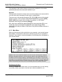
1
MVI46-GEC SLC Platform Generic ASCII Ethernet Interface Module User Manual April 30, 2008 Please Read This Notice Successful application of this module requires a reasonable working knowledge of the Rockwell Automation SLC hardware, the MVI46-GEC Module and the application in which the combination is to be used. For this reason, it is important that those responsible for implementation satisfy themselves that the combination will meet the needs of the application without exposing personnel or equipment to unsafe or inappropriate working conditions. This manual is provided to assist the user. Every attempt has been made to ensure that the information provided is accurate and a true reflection of the product's installation requirements. In order to ensure a complete understanding of the operation of the product, the user should read all applicable Rockwell Automation documentation on the operation of the Rockwell Automation hardware. Under no conditions will ProSoft Technology be responsible or liable for indirect or consequential damages resulting from the use or application of the product. Reproduction of the contents of this manual, in whole or in part, without written permission from ProSoft Technology is prohibited. Information in this manual is subject to change without notice and does not represent a commitment on the part of ProSoft Technology Improvements and/or changes in this manual or the product may be made at any time. These changes will be made periodically to correct technical inaccuracies or typographical errors. Battery Life Advisory All modules in the MVI series use a rechargeable Lithium Vanadium Pentoxide battery to backup the 512K SRAM memory, real-time clock, and CMOS. The battery should last for the life of the module. The module must be powered for approximately twenty hours before it becomes fully charged. After it is fully charged, the battery provides backup power for the CMOS setup and configuration data, the real-time clock, and the 512K SRAM memory for approximately 21 days. Before you remove a module from its power source, ensure that the battery within the module is fully charged. A fully charged battery will hold the BIOS settings (after being removed from its power source) for a limited number of days (15 for the PC56). When the battery is fully discharged, the module will revert to the default BIOS settings. Note: The battery is not user replaceable. Your Feedback Please We always want you to feel that you made the right decision to use our products. If you have suggestions, comments, compliments or complaints about the product, documentation or support, please write or call us. ProSoft Technology 1675 Chester Avenue, Fourth Floor Bakersfield, CA 93301 +1 (661) 716-5100 +1 (661) 716-5101 (Fax) http://www.prosoft-technology.com Copyright © ProSoft Technology, Inc. 2000 - 2008. All Rights Reserved. MVI46-GEC User Manual April 30, 2008 PSFT..MVI46.UM.08.04.30 ProSoft Technology ®, ProLinx ®, inRAx ®, ProTalk® and RadioLinx ® are Registered Trademarks of ProSoft Technology, Inc. ProSoft® Product Documentation In an effort to conserve paper, ProSoft Technology no longer includes printed manuals with our product shipments. User Manuals, Datasheets, Sample Ladder Files, and Configuration Files are provided on the enclosed CD and are available at no charge from our web site: http://www.prosoft-technology.com Printed documentation is available for purchase. Contact ProSoft Technology for pricing and availability. Asia Pacific: +603.7724.2080 Europe, Middle East, South Africa: +33.5.34.36.87.20 Latin America: +1.281.298.9109 North America: +1.661.716.5100 Contents MVI46-GEC ♦ SLC Platform Generic ASCII Ethernet Interface Module Contents PLEASE READ THIS NOTICE................................................................................................................ 2 Battery Life Advisory.......................................................................................................................... 2 Your Feedback Please ...................................................................................................................... 2 ProSoft® Product Documentation ..................................................................................................... 3 GUIDE TO THE MVI46-GEC USER MANUAL ....................................................................................... 7 1 START HERE.................................................................................................................................... 9 1.1 System Requirements................................................................................................................. 9 1.2 Package Contents..................................................................................................................... 10 1.3 Install ProSoft Configuration Builder Software.......................................................................... 10 1.4 Setting Jumpers ........................................................................................................................ 12 1.5 Install the Module in the Rack................................................................................................... 12 1.6 Connect your PC to the Processor ........................................................................................... 14 1.7 Download the Sample Program to the Processor..................................................................... 15 1.7.1 2 Configuring RSLinx.................................................................................................................... 16 1.8 Connect your PC to the Module................................................................................................ 17 MODULE CONFIGURATION.......................................................................................................... 19 2.1 Installing and Configuring the Module....................................................................................... 19 2.2 Module Data.............................................................................................................................. 21 2.3 ProSoft Configuration Builder ................................................................................................... 21 2.3.1 2.3.2 Set Up the Project ..................................................................................................................... 22 Set Module Parameters ............................................................................................................. 24 2.4 [Module] .................................................................................................................................... 26 2.4.1 Module Name ............................................................................................................................ 26 2.5 [Server x]................................................................................................................................... 26 2.5.1 2.5.2 2.5.3 2.5.4 2.5.5 2.5.6 3 4 Enabled ..................................................................................................................................... 26 Service Port Number ................................................................................................................. 26 Connection Timeout .................................................................................................................. 26 Connection Close Type ............................................................................................................. 27 Swap Rx Data Bytes.................................................................................................................. 27 Swap Tx Data Bytes .................................................................................................................. 27 2.6 Ethernet Configuration .............................................................................................................. 27 2.7 Download the Project to the Module ......................................................................................... 28 LADDER LOGIC ............................................................................................................................. 31 DIAGNOSTICS AND TROUBLESHOOTING ................................................................................. 33 4.1 Reading Status Data from the Module...................................................................................... 33 4.1.1 4.1.2 4.1.3 4.1.4 Required Hardware ................................................................................................................... 33 The Configuration/Debug Menu................................................................................................. 34 Main Menu................................................................................................................................. 36 Network Menu ........................................................................................................................... 39 4.2 LED Status Indicators ............................................................................................................... 40 4.2.1 4.2.2 4.2.3 5 Ethernet LED Indicators ............................................................................................................ 41 Clearing a Fault Condition ......................................................................................................... 41 Troubleshooting......................................................................................................................... 41 REFERENCE................................................................................................................................... 43 5.1 Product Specifications............................................................................................................... 43 5.1.1 5.1.2 5.1.3 5.1.4 Features and Benefits ............................................................................................................... 43 General Specifications............................................................................................................... 43 Hardware Specifications ............................................................................................................ 44 Functional Specifications ........................................................................................................... 44 ProSoft Technology, Inc. April 30, 2008 Page 5 of 78 Contents MVI46-GEC ♦ SLC Platform Generic ASCII Ethernet Interface Module 5.2 Functional Overview ................................................................................................................. 45 5.2.1 General Concepts ..................................................................................................................... 45 5.3 Cable Connections ................................................................................................................... 56 5.3.1 5.3.2 5.3.3 6 Ethernet Connection.................................................................................................................. 56 RS-232 Configuration/Debug Port............................................................................................. 57 DB9 to RJ45 Adaptor (Cable 14)............................................................................................... 59 5.4 MVI46-GEC Status Data Area.................................................................................................. 59 5.5 MVI46-GEC Configuration Data ............................................................................................... 65 SUPPORT, SERVICE & WARRANTY ........................................................................................... 67 6.1 How to Contact Us: Sales and Support.................................................................................... 68 6.2 Return Material Authorization (RMA) Policies and Conditions................................................. 68 6.2.1 All Product Returns ................................................................................................................... 69 6.3 Procedures for Return of Units Under Warranty ...................................................................... 69 6.4 Procedures for Return of Units Out of Warranty ...................................................................... 70 6.4.1 6.4.2 Un-repairable Units ................................................................................................................... 70 Purchasing Warranty Extension ................................................................................................ 71 6.5 LIMITED WARRANTY.............................................................................................................. 71 6.5.1 6.5.2 6.5.3 6.5.4 6.5.5 6.5.6 6.5.7 6.5.8 6.5.9 6.5.10 6.5.11 What Is Covered By This Warranty ........................................................................................... 71 What Is Not Covered By This Warranty..................................................................................... 72 DISCLAIMER REGARDING HIGH RISK ACTIVITIES .............................................................. 73 DISCLAIMER OF ALL OTHER WARRANTIES......................................................................... 73 LIMITATION OF REMEDIES**.................................................................................................. 73 Time Limit for Bringing Suit ....................................................................................................... 73 No Other Warranties ................................................................................................................. 74 Intellectual Property................................................................................................................... 74 Additional Restrictions Relating To Software And Other Intellectual Property........................... 74 Allocation of risks ...................................................................................................................... 74 Controlling Law and Severability ............................................................................................... 75 INDEX.................................................................................................................................................... 77 Page 6 of 78 ProSoft Technology, Inc. April 30, 2008 Start Here MVI46-GEC ♦ SLC Platform Generic ASCII Ethernet Interface Module Guide to the MVI46-GEC User Manual Function Introduction Details Start Here (page 9) This Section introduces the customer to the module. Included are: package contents, system requirements, hardware installation, and basic configuration. Verifying Communication (page 40) This section describes how to verify communications with the network. Diagnostic and Troubleshooting procedures. → (Must Do) Verify Communication, Diagnostic and Troubleshooting Section to Read → Diagnostics and Troubleshooting (page 33) Reference → Product Specifications Functional Overview (page 45) Functional Overview Glossary Support, Service, and Warranty Index ProSoft Technology, Inc. April 30, 2008 Reference (page 43) These sections contain general references associated with this product, Specifications, and the Functional Overview. Product Specifications (page 43) → Support, Service and Warranty (page 67) This section contains Support, Service and Warranty information. Index of chapters. Page 7 of 78 MVI46-GEC ♦ SLC Platform Generic ASCII Ethernet Interface Module Page 8 of 78 Start Here ProSoft Technology, Inc. April 30, 2008 Start Here 1 MVI46-GEC ♦ SLC Platform Generic ASCII Ethernet Interface Module Start Here In This Chapter System Requirements ............................................................................. 9 Package Contents ................................................................................. 10 Install ProSoft Configuration Builder Software....................................... 10 Setting Jumpers .................................................................................... 12 Install the Module in the Rack ............................................................... 12 Connect your PC to the Processor ........................................................ 14 Download the Sample Program to the Processor.................................. 15 Connect your PC to the Module ............................................................ 17 Installing the MVI46-GEC module requires a reasonable working knowledge of the Rockwell Automation hardware, the MVI46-GEC Module and the application in which they will be used. Caution: It is important that those responsible for implementation can complete the application without exposing personnel, or equipment, to unsafe or inappropriate working conditions. Safety, quality and experience are key factors in a successful installation. 1.1 System Requirements The MVI46-GEC module requires the following minimum hardware and software components: Rockwell Automation SLC 5/02 M0/M1 capable processors (or newer), with compatible power supply and one free slot in the rack, for the MVI46-GEC module. The module requires 800mA of available power. Rockwell Automation RSLogix 500 programming software. Rockwell Automation RSLinx communication software Pentium® II 500 MHz minimum. Pentium III 733 MHz (or better) recommended Supported operating systems: o Microsoft® Windows 98 o Windows NT® (version 4 with SP4 or higher) o Windows 2000 o Windows XP 32 Mbytes of RAM minimum, 64 Mbytes of RAM recommended 50 Mbytes of free hard disk space (or more based on application requirements) ProSoft Technology, Inc. April 30, 2008 Page 9 of 78 MVI46-GEC ♦ SLC Platform Generic ASCII Ethernet Interface Module 1.2 Start Here 16-color VGA graphics adapter, 640 x 480 minimum resolution (256 Color 800 × 600 recommended) CD-ROM drive 3.5 inch floppy disk drive HyperTerminal or other terminal emulator program capable of file transfers using Zmodem protocol. Package Contents The following components are included with your MVI46-GEC module, and are all required for installation and configuration. Important: Before beginning the installation, please verify that all of the following items are present. Qty. Part Name Part Number Part Description 1 MVI46-GEC Module MVI46-GEC Generic ASCII Ethernet Interface Module 1 Cable Cable #15, RS232 Null Modem For RS232 Connection to the CFG Port 1 Cable RJ45 to DB9 Male Adapter For DB9 Connection to Module's Port 1 inRAx Solutions CD Contains sample programs, utilities and documentation for the MVI46-GEC module. If any of these components are missing, please contact ProSoft Technology Support for replacement parts. 1.3 Install ProSoft Configuration Builder Software You must install the ProSoft Configuration Builder (PCB) software in order to configure the MVI46-GEC module. You can always get the newest version of ProSoft Configuration Builder from the ProSoft Technology web site. To install ProSoft Configuration Builder from the ProSoft Web Site 1 2 Open your web browser and navigate to http://www.prosofttechnology.com/pcb Click the Download Here link to download the latest version of ProSoft Configuration Builder. Page 10 of 78 ProSoft Technology, Inc. April 30, 2008 Start Here MVI46-GEC ♦ SLC Platform Generic ASCII Ethernet Interface Module 3 Choose "Save" or "Save File" when prompted. The following illustrations show the file download prompt for two of the most common web browsers. 4 Make a note of the location where you saved the file, for example "Desktop", or "My Documents", so you can start the installation program. When the download is complete, locate and open the file, and then follow the instructions on your screen to install the program. 5 If you do not have access to the Internet, you can install ProSoft Configuration Builder from the ProSoft Solutions CD-ROM, included in the package with your MVI46-GEC module. To install ProSoft Configuration Builder from the CD-ROM 1 2 3 4 Insert the ProSoft Solutions CD-ROM into the CD drive of your PC. Wait for the startup screen to appear. On the startup screen, click Product Documentation. This action opens an explorer window. Click to open the Utilities folder. This folder contains all of the applications and files you will need to set up and configure your module. Double-click the ProSoft Configuration Builder Setup program and follow the instructions on your screen to install the software on your PC. Note: Many of the configuration and maintenance procedures use files and other utilities on the CD-ROM. You may wish to copy the files from the Utilities folder on the CD-ROM to a convenient location on your hard drive. ProSoft Technology, Inc. April 30, 2008 Page 11 of 78 MVI46-GEC ♦ SLC Platform Generic ASCII Ethernet Interface Module 1.4 Start Here Setting Jumpers Note: The Setup Jumper acts as "write protection" for the module's flash memory. In "write protected" mode, the Setup pins are not connected, and the module's firmware cannot be overwritten. Do not jumper the Setup pins together unless you are directed to do so by ProSoft Technical Support. 1.5 Install the Module in the Rack If you have not already installed and configured your SLC processor and power supply, please do so before installing the MVI46-GEC module. Refer to your Rockwell Automation product documentation for installation instructions. Warning: You must follow all safety instructions when installing this or any other electronic devices. Failure to follow safety procedures could result in damage to hardware or data, or even serious injury or death to personnel. Refer to the documentation for each device you plan to connect to verify that suitable safety procedures are in place before installing or servicing the device. After you have checked the placement of the jumpers, insert MVI46-GEC into the SLC™ chassis. Use the same technique recommended by Rockwell Automation to remove and install SLC™ modules. Page 12 of 78 ProSoft Technology, Inc. April 30, 2008 Start Here MVI46-GEC ♦ SLC Platform Generic ASCII Ethernet Interface Module Warning: This module is not hot-swappable! Always remove power from the rack before inserting or removing this module, or damage may result to the module, the processor, or other connected devices. 1 2 Turn power OFF. Align the module with the top and bottom guides, and slide it into the rack until the module is firmly against the backplane connector. 3 4 With a firm but steady push, snap the module into place. Check that the holding clips on the top and bottom of the module are securely in the locking holes of the rack. Make a note of the slot location. You will need to identify the slot in which the module is installed in order for the sample program to work correctly. Slot numbers are identified on the green circuit board (backplane) of the SLC rack. Turn power ON. 5 6 Note: If you insert the module improperly, the system may stop working, or may behave unpredictably. ProSoft Technology, Inc. April 30, 2008 Page 13 of 78 MVI46-GEC ♦ SLC Platform Generic ASCII Ethernet Interface Module 1.6 Start Here Connect your PC to the Processor 1 Connect the right-angle connector end of the cable to your controller at the communications port. 2 Connect the straight connector end of the cable to the serial port on your computer. Page 14 of 78 ProSoft Technology, Inc. April 30, 2008 Start Here 1.7 MVI46-GEC ♦ SLC Platform Generic ASCII Ethernet Interface Module Download the Sample Program to the Processor To download the sample program from RSLogix 500 to the SLC processor: Note: The key switch on the front of the SLC processor must be in the REM position. 1 If you are not already online to the processor, open the Communications menu, and then choose Download. RSLogix will establish communication with the processor. 2 3 Click the Download button to transfer the sample program to the processor. RSLogix will compile the program and transfer it to the processor. This process may take a few minutes. 4 When the download is complete, RSLogix will open another confirmation dialog box. Click Yes to switch the processor from Program mode to Run mode. Note: If you receive an error message during these steps, refer to your RSLogix documentation to interpret and correct the error. ProSoft Technology, Inc. April 30, 2008 Page 15 of 78 MVI46-GEC ♦ SLC Platform Generic ASCII Ethernet Interface Module Start Here 1.7.1 Configuring RSLinx If RSLogix is unable to establish communication with the processor, follow these steps: 1 2 Open RSLinx. Open the Communications menu, and choose Configure Drivers. This action opens the Configure Drivers dialog box. Note: If the list of configured drivers is blank, you must first choose and configure a driver from the Available Driver Types list. The recommended driver type to choose for serial communication with the processor is "RS-232 DF1 Devices". Page 16 of 78 ProSoft Technology, Inc. April 30, 2008 Start Here MVI46-GEC ♦ SLC Platform Generic ASCII Ethernet Interface Module 3 Click to select the driver, and then click Configure. This action opens the Configure Allen-Bradley DF1 Communications Device dialog box. 4 Click the Auto-Configure button. RSLinx will attempt to configure your serial port to work with the selected driver. When you see the message "Auto Configuration Successful", click the OK button to dismiss the dialog box. 5 Note: If the auto-configuration procedure fails, verify that the cables are connected correctly between the processor and the serial port on your computer, and then try again. If you are still unable to auto-configure the port, refer to your RSLinx documentation for further troubleshooting steps. 1.8 Connect your PC to the Module With the module securely mounted, connect your PC to the Configuration/Debug port using an RJ45-DB-9 Serial Adapter Cable and a Null Modem Cable. 1 2 Attach both cables as shown. Insert the RJ45 cable connector into the Configuration/Debug port of the module. ProSoft Technology, Inc. April 30, 2008 Page 17 of 78 MVI46-GEC ♦ SLC Platform Generic ASCII Ethernet Interface Module 3 Start Here Attach the other end to the serial port on your PC or laptop. Page 18 of 78 ProSoft Technology, Inc. April 30, 2008 Module Configuration 2 MVI46-GEC ♦ SLC Platform Generic ASCII Ethernet Interface Module Module Configuration In This Chapter Installing and Configuring the Module ................................................... 19 Module Data .......................................................................................... 21 ProSoft Configuration Builder ................................................................ 21 [Module]................................................................................................. 26 [Server x] ............................................................................................... 26 Ethernet Configuration .......................................................................... 27 Download the Project to the Module...................................................... 28 This section contains the setup procedure, data, and ladder logic for successful application of the MVI46-GEC module. Each step in the setup procedure is defined in order to simplify the use of the module. 2.1 Installing and Configuring the Module This chapter describes how to install and configure the module to work with your application. The configuration process consists of the following steps. 1 Use RSLogix to identify the module to the processor and add the module to a project. Note: The RSLogix software must be in "offline" mode to add the module to a project. 2 3 Modify the module's configuration files to meet the needs of your application, and copy the updated configuration to the module. Example configuration files are provided on the CD-ROM. Refer to the Modifying the Example Configuration File section, later in this chapter, for more information on the configuration files. Modify the example ladder logic to meet the needs of your application, and copy the ladder logic to the processor. Example ladder logic files are provided on the CD-ROM. Note: If you are installing this module in an existing application, you can copy the necessary elements from the example ladder logic into your application. The rest of this chapter describes these steps in more detail. ProSoft Technology, Inc. April 30, 2008 Page 19 of 78 MVI46-GEC ♦ SLC Platform Generic ASCII Ethernet Interface Module Module Configuration The first step in installing and configuring the module is to define the module to the system. Select the I/O Configuration option from the program screen. The system displays the following window: Select the Other module from the list. This causes the system to display the following dialog box: Enter the module I/O card ID number as 12835, then click OK. Double-click the mouse on the module just added to the rack. Fill in the dialog box as shown: Click OK to apply the settings. Close this dialog box. Page 20 of 78 ProSoft Technology, Inc. April 30, 2008 Module Configuration MVI46-GEC ♦ SLC Platform Generic ASCII Ethernet Interface Module The next step in the module's setup is to define the user-defined data areas to hold the status and read and write database areas. Edit the GEC.CFG file now for the application to implement. Use any text editor to set the values in the file. You must retain the file name GEC.CFG. The last step in the module setup is to add the ladder logic. If the example ladder logic is used, adjust the ladder to fit the application. When the ladder example is not used, copy the example ladder logic to your application and alter as necessary. The module is now ready to be used with your application. Insert the module in the rack (with the power turned off) and attach the serial communication cables. Download the new GEC.CFG file to the module using a terminal emulation program. Download the new application to the controller and place the processor in run mode. If all the configuration parameters are set correctly and the module is attached to a network, the module's Application LED (APP LED) should remain off and the backplane activity LED (BP ACT) should blink very rapidly. Refer to the Troubleshooting section if you encounter errors. Attach a terminal to the Debug/Configuration port on the module and look at the status of the module using the Configuration/Debug Menu in the module. 2.2 Module Data All data related to the MVI46-GEC module is stored in a user defined data file and the module's M0 and M1 files. Files should be defined for each server for a transmit and receive buffer to be used with the module. Additionally, a file should be defined to hold the module status data. The status data should be copied from the M1 file and placed in the assigned status file. The ladder logic is responsible for transferring all received data from a server into the user data files and for transferring all user data to the M0 file to be sent to a specific server. 2.3 ProSoft Configuration Builder ProSoft Configuration Builder (PCB) provides a quick and easy way to manage module configuration files customized to meet your application needs. PCB is not only a powerful solution for new configuration files, but also allows you to import information from previously installed (known working) configurations to new projects. ProSoft Technology, Inc. April 30, 2008 Page 21 of 78 MVI46-GEC ♦ SLC Platform Generic ASCII Ethernet Interface Module Module Configuration 2.3.1 Set Up the Project To begin, start ProSoft Configuration Builder. If you have used other Windows configuration tools before, you will find the screen layout familiar. ProSoft Configuration Builder's window consists of a tree view on the left, an information pane and a configuration pane on the right side of the window. When you first start ProSoft Configuration Builder, the tree view consists of folders for Default Project and Default Location, with a Default Module in the Default Location folder. The following illustration shows the ProSoft Configuration Builder window with a new project. Your first task is to add the MVI46-GEC module to the project. 1 Use the mouse to select "Default Module" in the tree view, and then click the right mouse button to open a shortcut menu. Page 22 of 78 ProSoft Technology, Inc. April 30, 2008 Module Configuration MVI46-GEC ♦ SLC Platform Generic ASCII Ethernet Interface Module 2 On the shortcut menu, choose "Choose Module Type". This action opens the Choose Module Type dialog box. 3 In the Product Line Filter area of the dialog box, select MVI46. In the Select Module Type dropdown list, select MVI46-GEC, and then click OK to save your settings and return to the ProSoft Configuration Builder window. The next task is to set the module parameters. Adding a Module To add a module to your project: 1 2 Double-click the Default Module icon to open the Choose Module Type dialog box. On the Choose Module Type dialog box, select the module type. Or 1 2 Open the Project menu and choose Location. On the Location menu, choose Add Module. To add a module to a different location: 1 Right-click the Location folder and choose Add Module. A new module icon appears. Or 1 2 Select the Location icon. From the Project menu, select Location, then select Add Module. ProSoft Technology, Inc. April 30, 2008 Page 23 of 78 MVI46-GEC ♦ SLC Platform Generic ASCII Ethernet Interface Module Module Configuration Adding a Project To add a project to an existing project file: 1 2 Select the Default Project icon. Choose Project from the Project menu, then choose Add Project. A new project folder appears. 2.3.2 Set Module Parameters Notice that the contents of the information pane and the configuration pane changed when you added the MVI46-GEC module to the project. At this time, you may wish to rename the "Default Project" and "Default Location" folders in the tree view. To rename an object: 1 2 3 Select the object, and then click the right mouse button to open a shortcut menu. From the shortcut menu, choose Rename. Type the name to assign to the object. Click away from the object to save the new name. Page 24 of 78 ProSoft Technology, Inc. April 30, 2008 Module Configuration MVI46-GEC ♦ SLC Platform Generic ASCII Ethernet Interface Module Module Entries To configure module parameters 1 2 3 4 Click on the plus sign next to the icon to expand module information. Double-click the icon to open the Edit dialog box. To edit a parameter, select the parameter in the left pane and make your changes in the right pane. Click OK to save your changes. Comment Entries To add comments to your configuration file: 1 2 3 icon to expand the Module Click the plus sign to the left of the Comments. Double-click the icon. The Edit - Module Comment dialog appears. Enter your comment and click OK to save your changes. Printing a Configuration File To print a configuration file: 1 2 3 4 Select the Module icon, and then click the right mouse button to open a shortcut menu. On the shortcut menu, choose View Configuration. This action opens the View Configuration window. On the View Configuration window, open the File menu, and choose Print. This action opens the Print dialog box. On the Print dialog box, choose the printer to use from the dropdown list, select printing options, and then click OK. ProSoft Technology, Inc. April 30, 2008 Page 25 of 78 MVI46-GEC ♦ SLC Platform Generic ASCII Ethernet Interface Module 2.4 Module Configuration [Module] This section of the file describes the database setup and module level parameters. [Module] Module Name: MVI46-GEC Communication Module DEFAULT 2.4.1 Module Name 0 to 80 characters This parameter assigns a name to the module that can be viewed using the configuration/debug port. Use this parameter to identify the module and the configuration file. 2.5 [Server x] You can configure up to five servers ([Server 0] through [Server 4]). The configuration section for each server contains the same set of parameters. You can configure the parameters for each server to meet the requirements of your application. 2.5.1 Enabled Yes or No This parameter determines if the server will be utilized by the module. If a value of 'Yes' is entered, the server will be used. Any other value will disable the server. 2.5.2 Service Port Number 1 to 65535 This parameter sets the TCP/IP service port for this server. Each server can have its own unique service port or can share the same number with other servers. 2.5.3 Connection Timeout 0 or 5000 to 65535 This parameter specifies the number of milliseconds the server will permit the server to be inactive after a connection is made before closing the socket. This timeout period is reset on each read or write packet. If the parameter is set to 0, the connection will not timeout. Page 26 of 78 ProSoft Technology, Inc. April 30, 2008 Module Configuration MVI46-GEC ♦ SLC Platform Generic ASCII Ethernet Interface Module 2.5.4 Connection Close Type 0, 1 or 2 This coded parameter defines the personality of the server after a connection is made. If the parameter is set to 0, the socket will only be closed when a request from the client is received or the connection timeout is exceeded. If a value of 1 is selected, the server will close the socket after it transmits a single message. If a value of 2 is selected, the server will close the socket after it receives a message. 2.5.5 Swap Rx Data Bytes Yes or No This parameter determines if the data received by the server will have the byte order of the data swapped. If the parameter is set to No, no byte swapping will occur. If the parameter is set to Yes, the odd byte will be swapped with the even byte in each word of data received. 2.5.6 Swap Tx Data Bytes Yes or No This parameter determines if the data to be transmitted by the module will have the byte order of the data swapped. If the parameter is set to No, no byte swapping will occur. If the parameter is set to Yes, the odd byte will be swapped with the even byte in each word of data received. 2.6 Ethernet Configuration Use this procedure to configure the Ethernet settings for your module. You must assign an IP address, subnet mask and gateway address. After you complete this step, you can connect to the module with an Ethernet cable. 1 Determine the network settings for your module, with the help of your network administrator if necessary. You will need the following information: o IP address (fixed IP required) _____ . _____ . _____ . _____ o Subnet mask _____ . _____ . _____ . _____ 2 Gateway address _____ . _____ . _____ . _____Click [+] to expand the tree for the MVI46-GEC module. ProSoft Technology, Inc. April 30, 2008 Page 27 of 78 MVI46-GEC ♦ SLC Platform Generic ASCII Ethernet Interface Module 3 Double-click the Ethernet Configuration object. This action opens the Edit dialog box. 4 Edit the values for my_ip, netmask (subnet mask) and gateway (default gateway). When you are finished editing, click OK to save your changes and return to the ProSoft Configuration Builder window. 5 2.7 Module Configuration Download the Project to the Module In order for the module to use the settings you configured, you must download (copy) the updated Project file from your PC to the module. To Download the Project File 1 2 In the tree view in ProSoft Configuration Builder, click once to select the MVI46-GEC module. Open the Project menu, and then choose Module / Download. The program will scan your PC for a valid com port (this may take a few seconds). When PCB has found a valid com port, the following dialog box will open. Page 28 of 78 ProSoft Technology, Inc. April 30, 2008 Module Configuration 3 MVI46-GEC ♦ SLC Platform Generic ASCII Ethernet Interface Module Choose the com port to use from the dropdown list, and then click the Download button. The module will perform a platform check to read and load its new settings. When the platform check is complete, the status bar in ProSoft Configuration Builder will be updated with the message "Module Running". ProSoft Technology, Inc. April 30, 2008 Page 29 of 78 MVI46-GEC ♦ SLC Platform Generic ASCII Ethernet Interface Module Page 30 of 78 Module Configuration ProSoft Technology, Inc. April 30, 2008 Ladder Logic 3 MVI46-GEC ♦ SLC Platform Generic ASCII Ethernet Interface Module Ladder Logic Ladder logic is required for application of the MVI46-GEC module. Tasks that must be handled by the ladder logic are module data transfer, special block handling and status data receipt. Additionally, a power-up handler may be needed to handle the initialization of the module's data and to clear any processor fault conditions. The sample ladder logic, on the ProSoft Solutions CD-ROM, is extensively commented, to provide information on the purpose and function of each rung. For most applications, the sample ladder will work without modification. ProSoft Technology, Inc. April 30, 2008 Page 31 of 78 MVI46-GEC ♦ SLC Platform Generic ASCII Ethernet Interface Module Page 32 of 78 Ladder Logic ProSoft Technology, Inc. April 30, 2008 Diagnostics and Troubleshooting 4 MVI46-GEC ♦ SLC Platform Generic ASCII Ethernet Interface Module Diagnostics and Troubleshooting In This Chapter Reading Status Data from the Module .................................................. 33 LED Status Indicators............................................................................ 40 The module provides information on diagnostics and troubleshooting in the following forms: 4.1 Status data values are transferred from the module to the processor. Data contained in the module can be viewed through the Configuration/Debug port attached to a terminal emulator. LED status indicators on the front of the module provide information on the module's status. Reading Status Data from the Module The MVI46-GEC module returns a status data set to the SLC processor in each read block (M1 file). This data is transferred to the SLC processor continuously with each read block. The Configuration/Debug port provides the following functionality: Full view of the module's configuration data View of the module's status data Complete display of the module's internal database (registers 0 to 3999) Version Information Control over the module (warm boot, cold boot, transfer configuration) Facility to upload and download the module's configuration file 4.1.1 Required Hardware You can connect directly from your computer's serial port to the serial port on the module to view configuration information, perform maintenance, and send (upload) or receive (download) configuration files. ProSoft Technology recommends the following minimum hardware to connect your computer to the module: 80486 based processor (Pentium preferred) 1 megabyte of memory At least one UART hardware-based serial communications port available. USB-based virtual UART systems (USB to serial port adapters) often do not function reliably, especially during binary file transfers, such as when uploading/downloading configuration files or module firmware upgrades. A null modem serial cable. ProSoft Technology, Inc. April 30, 2008 Page 33 of 78 MVI46-GEC ♦ SLC Platform Generic ASCII Ethernet Interface Module Diagnostics and Troubleshooting 4.1.2 The Configuration/Debug Menu The Configuration and Debug menu for this module is arranged as a tree structure, with the Main Menu at the top of the tree, and one or more sub-menus for each menu command. The first menu you see when you connect to the module is the Main menu. Because this is a text-based menu system, you enter commands by typing the command letter from your computer keyboard in the diagnostic window in ProSoft Configuration Builder (PCB). The module does not respond to mouse movements or clicks. The command executes as soon as you press the command letter — you do not need to press [Enter]. When you type a command letter, a new screen will be displayed in your terminal application. Using the Diagnostic Window in ProSoft Configuration Builder To connect to the module's Configuration/Debug serial port: 1 Start PCB program with the application file to be tested. Right click over the module icon. 2 On the shortcut menu, choose Diagnostics. Page 34 of 78 ProSoft Technology, Inc. April 30, 2008 Diagnostics and Troubleshooting 3 MVI46-GEC ♦ SLC Platform Generic ASCII Ethernet Interface Module This action opens the Diagnostics dialog box. Press "?" to display the Main Menu. Important: The illustrations of configuration/debug menus in this section are intended as a general guide, and may not exactly match the configuration/debug menus in your own module. If there is no response from the module, follow these steps: 1 2 Verify that the null modem cable is connected properly between your computer's serial port and the module. A regular serial cable will not work. On computers with more than one serial port, verify that your communication program is connected to the same port that is connected to the module. If you are still not able to establish a connection, contact ProSoft Technology for assistance. Navigation All of the sub-menus for this module contain commands to redisplay the menu or return to the previous menu. You can always return from a sub-menu to the next higher menu by pressing [M] on your keyboard. The organization of the menu structure is represented in simplified form in the following illustration: ProSoft Technology, Inc. April 30, 2008 Page 35 of 78 MVI46-GEC ♦ SLC Platform Generic ASCII Ethernet Interface Module Diagnostics and Troubleshooting The remainder of this section shows you the menus available for this module, and briefly discusses the commands available to you. Keystrokes The keyboard commands on these menus are almost always non-case sensitive. You can enter most commands in lower case or capital letters. The menus use a few special characters ([?], [-], [+], [@]) that must be entered exactly as shown. Some of these characters will require you to use the [Shift], [Ctrl] or [Alt] keys to enter them correctly. For example, on US English keyboards, enter the [?] command as [Shift][/]. Also, take care to distinguish capital letter [I] from lower case letter [l] (L) and number [1]; likewise for capital letter [O] and number [0]. Although these characters look nearly the same on the screen, they perform different actions on the module. 4.1.3 Main Menu When you first connect to the module from your computer, your terminal screen will be blank. To activate the main menu, press the [?] key on your computer's keyboard. If the module is connected properly, the following menu will appear on your terminal screen: Caution: Some of the commands available to you from this menu are designed for advanced debugging and system testing only, and can cause the module to stop communicating with the processor or with other devices, resulting in potential data loss or other failures. Only use these commands if you are specifically directed to do so by ProSoft Technology Technical Support staff. Some of these command keys are not listed on the menu, but are active nevertheless. Please be careful when pressing keys so that you do not accidentally execute an unwanted command. Redisplaying the Menu Press [?] to display the current menu. Use this command when you are looking at a screen of data, and want to view the menu choices available to you. Page 36 of 78 ProSoft Technology, Inc. April 30, 2008 Diagnostics and Troubleshooting MVI46-GEC ♦ SLC Platform Generic ASCII Ethernet Interface Module Viewing Block Transfer Statistics Press [B] to view the Block Transfer Statistics screen. Use this command to display the configuration and statistics of the backplane data transfer operations between the module and the processor. The information on this screen can help determine if there are communication problems between the processor and the module. Tip: Repeat this command at one-second intervals to determine the number of blocks transferred each second. Viewing Module Configuration Press [C] to view the Module Configuration screen. Use this command to display the current configuration and statistics for the module. Transferring the Configuration File from PC to MVI46 module Press [R] to send (upload) the configuration file from your PC to the module and store the file on the module's Compact Flash Disk. Press [Y] to confirm the file transfer, and then follow the instructions on the terminal screen to complete the file transfer process. After the file has been successfully downloaded, the module will restart the program and load the new configuration information. Review the new configuration using menu commands [6] and [0] to verify that the module is configured correctly. Transferring the Configuration File from MVI46 module to PC Press [S] to receive (download) the configuration file from the module to your PC. Press [Y] to confirm the file transfer, and then follow the instructions on the terminal screen to complete the file transfer process. After the file has been successfully downloaded, you can open and edit the file to change the module's configuration. Resetting diagnostic data Press [U] to reset the status counters for the client and/or servers in the module. Viewing Version Information Press [V] to view Version information for the module. Use this command to view the current version of the software for the module, as well as other important values. You may be asked to provide this information when calling for technical support on the product. ProSoft Technology, Inc. April 30, 2008 Page 37 of 78 MVI46-GEC ♦ SLC Platform Generic ASCII Ethernet Interface Module Diagnostics and Troubleshooting Values at the bottom of the display are important in determining module operation. The Program Scan Counter value is incremented each time a module's program cycle is complete. Tip: Repeat this command at one-second intervals to determine the frequency of program execution. Warm Booting the Module Caution: Some of the commands available to you from this menu are designed for advanced debugging and system testing only, and can cause the module to stop communicating with the processor or with other devices, resulting in potential data loss or other failures. Only use these commands if you are specifically directed to do so by ProSoft Technology Technical Support staff. Some of these command keys are not listed on the menu, but are active nevertheless. Please be careful when pressing keys so that you do not accidentally execute an unwanted command. Press [W] from the Main Menu to warm boot (restart) the module. This command will cause the program to exit and reload, refreshing configuration parameters that must be set on program initialization. Only use this command if you must force the module to re-boot. Viewing Server Communication Status (Servers 0 to 4) Use commands [1] [2] [3] [4] or [5] to view the communication status and statistics of the specified server. This information can be useful when troubleshooting communication problems. Viewing Client Communication Status (Clients 10 to 14) Use commands [E] [F] [G] [H] or [I] to view the communication status and statistics of the specified client. This information can be useful when troubleshooting communication problems. Page 38 of 78 ProSoft Technology, Inc. April 30, 2008 Diagnostics and Troubleshooting MVI46-GEC ♦ SLC Platform Generic ASCII Ethernet Interface Module Viewing Server Configuration (Servers 0 to 4) Use commands [6] [7] [8] [9] or [0] to view the configuration of the specified server. Opening the Network Menu Press [@] to open the network menu. The network menu allows you to send, receive and view the WATTCP.CFG file that contains the IP, gateway and other network specification information. You can find more information about the commands on this menu in the Network Menu (page 39) section. Exiting the Program Caution: Some of the commands available to you from this menu are designed for advanced debugging and system testing only, and can cause the module to stop communicating with the processor or with other devices, resulting in potential data loss or other failures. Only use these commands if you are specifically directed to do so by ProSoft Technology Technical Support staff. Some of these command keys are not listed on the menu, but are active nevertheless. Please be careful when pressing keys so that you do not accidentally execute an unwanted command. Press [Esc] to restart the module and force all drivers to be loaded. The module will use the configuration stored in the module's Flash ROM to configure the module. 4.1.4 Network Menu The network menu allows you to send, receive and view the WATTCP.CFG file that contains the IP and gateway addresses, and other network specification information. M = Main Menu @ = Network Menu ? = Display Menu Redisplays (refreshes) this menu R = Receive WATTCP.CFG Upload WATTCP.CFG to module S = Send WATTCP.CFG Download WATTCP.CFG to PC V = View WATTCP.CFG View WATTCP.CFG file on module M = Main Menu Return to Main Menu Transferring WATTCP.CFG to the module Press [R] to transfer a new WATTCP.CFG file from the PC to the module. Use this command to change the network configuration for the module (for example, the module's IP address). Press [Y] to confirm the file transfer, and then follow the instructions on the terminal screen to complete the file transfer process. ProSoft Technology, Inc. April 30, 2008 Page 39 of 78 MVI46-GEC ♦ SLC Platform Generic ASCII Ethernet Interface Module Diagnostics and Troubleshooting Transferring WATTCP.CFG to the PC Press [S] to transfer the WATTCP.CFG file from the module to your PC. Press [Y] to confirm the file transfer, and then follow the instructions on the terminal screen to complete the file transfer process. After the file has been successfully transferred, you can open and edit the file to change the module's network configuration. Viewing the WATTCP.CFG file on the module Press [V] to view the module's WATTCP.CFG file. Use this command to confirm the module's current network settings. Returning to the Main Menu Press [M] to return to the Main Menu. 4.2 LED Status Indicators The LEDs will indicate the module's operating status as follows: ProSoft Module Color Status Indication CFG Green On Data is being transferred between the module and a remote terminal using the Configuration/Debug port. Off No data is being transferred on the Configuration/Debug port. On Port not used Off Port not used P1 P2 Green Green APP Status Amber BP ACT Amber Page 40 of 78 On Port not used Off Port not used Off The MVI46-GEC is working normally. On The MVI46-GEC module program has recognized a communication error. On The LED is on when the module is performing a write operation on the backplane. Off The LED is off when the module is performing a read operation on the backplane. Under normal operation, the LED should blink rapidly on and off. ProSoft Technology, Inc. April 30, 2008 Diagnostics and Troubleshooting MVI46-GEC ♦ SLC Platform Generic ASCII Ethernet Interface Module ProSoft Module Color Status Indication OK Red/ Green Off The card is not receiving any power and is not securely plugged into the rack. Green The module is operating normally. Red The program has detected an error or is being configured. If the LED remains red for over 10 seconds, the program has probably halted. Remove the card from the rack and re-insert the card to restart the module's program. Off The battery voltage is OK and functioning. On The battery voltage is low or battery is not present. Allow battery to charge by keeping module plugged into rack for 24 hours. If BAT LED still does not go off, contact ProSoft Technology, as this is not a user serviceable item. BAT Red 4.2.1 Ethernet LED Indicators LED State Description Data Off No activity on the port. Green Flash The port is either actively transmitting or receiving data. Off No connection to hub or network is detected. Green Solid Connected to hub or network correctly. This is the normal operating state. Link 4.2.2 Clearing a Fault Condition Typically, if the OK LED on the front of the module turns red for more than ten seconds, a hardware problem has been detected in the module, or the program has exited. To clear the condition, follow these steps: 1 2 3 4 5 6 Turn off power to the rack Remove the card from the rack Verify that all jumpers are set correctly If the module requires a Compact Flash card, verify that the card is installed correctly Re-insert the card in the rack and turn the power back on Verify the configuration data being transferred to the module from the SLC processor. If the module's OK LED does not turn green, verify that the module is inserted completely into the rack. If this does not cure the problem, contact ProSoft Technology Support. 4.2.3 Troubleshooting Use the following troubleshooting steps if you encounter problems when the module is powered up. If these steps do not resolve your problem, please contact ProSoft Technology Technical Support. ProSoft Technology, Inc. April 30, 2008 Page 41 of 78 MVI46-GEC ♦ SLC Platform Generic ASCII Ethernet Interface Module Diagnostics and Troubleshooting Processor Errors Problem Description Steps to take Processor Fault Verify that the module is plugged into the slot that has been configured for the module. Verify that the slot in the rack configuration has been set up correctly in the ladder logic. Processor I/O LED flashes This indicates a problem with backplane communications. Verify that all modules in the rack are configured in the ladder logic. Module Errors Problem Description Steps to take BP ACT LED remains off or blinks slowly This indicates that backplane transfer operations are failing. Connect to the module's Configuration/Debug port to check this. To establish backplane communications, verify the following items: OK LED remains red Page 42 of 78 The processor is in Run mode. The backplane driver is loaded in the module. The module is configured for read and write block data transfer. The ladder logic handles all read and write block situations. The module is configured in the processor. The program has halted or a critical error has occurred. Connect to the Configuration/Debug port to see if the module is running. If the program has halted, turn off power to the rack, remove the card from the rack and re-insert the card in the rack, and then restore power to the rack. ProSoft Technology, Inc. April 30, 2008 Reference 5 MVI46-GEC ♦ SLC Platform Generic ASCII Ethernet Interface Module Reference In This Chapter 5.1 Product Specifications ........................................................................... 43 Functional Overview.............................................................................. 45 Cable Connections ................................................................................ 56 MVI46-GEC Status Data Area............................................................... 59 MVI46-GEC Configuration Data ............................................................ 65 Product Specifications The MVI46 Generic ASCII Ethernet Interface module is designed to allow SLC processors to interface easily with ASCII devices using the TCP/IP protocol and the SLC processor. Compatible devices may be either ASCII instruments with Ethernet built-in or Ethernet connection via a thin server to the existing ASCII device. 5.1.1 Features and Benefits Five servers and clients are present on the module permitting both the reception and transmission of data between the Rockwell Automation processor and attached devices. The MVI46-GEC module is a powerful communication interface for SLC processors. Developed under license from Rockwell Automation, the module incorporates proprietary backplane technology that enables powerful data access between the module and the SLC processor. 5.1.2 General Specifications Single Slot - 1746 backplane compatible (Local or extended I/O rack only. Remote rack not supported) The module is recognized as an Input/Output module and has access to processor memory for data transfer between processor and module using M0/M1 files Ladder Logic is used for data transfer between module and processor. Sample ladder file included Configuration data obtained from configuration text file downloaded to module. Sample configuration file included ProSoft Technology, Inc. April 30, 2008 Page 43 of 78 MVI46-GEC ♦ SLC Platform Generic ASCII Ethernet Interface Module Reference 5.1.3 Hardware Specifications Specification Description Backplane Current Load 800 ma @ 5V (from backplane) Operating Temperature 0 to 60°C (32 to 140°F) Storage Temperature -40 to 85°C (-40 to 185°F) Relative Humidity 5% to 95% (non-condensing) Shock 30g operational, 50g non-operational Vibration 5 g from 10150 Hz Processor Compatible with Rockwell Automation SLC 5/02 M0/M1 capable processors or newer LED indicators Module status, Backplane transfer status, Application status, Serial activity (debug port), Ethernet link and activity, and error LED status Debug/Configuration port (CFG) CFG Port (CFG) RJ45 (DB-9M with supplied cable) RS-232 only No hardware handshaking Configuration Connector RJ45 RS-232 Connector (RJ45 to DB-9 cable shipped with unit) Application Ports Ethernet Port (Ethernet Modules) RJ45 Connector Link and activity LED indicators Electrical Isolation 1500 V rms at 50 Hz to 60 Hz for 60 s, applied as specified in section 5.3.2 of IEC 60950: 1991 Ethernet Broadcast Storm Resiliency = less than or equal to 5000 [ARP] frames-per-second and less than or equal to 5 minutes duration 5.1.4 Functional Specifications Five Servers and Clients to receive and/or transmit data 10/100 Base-T Ethernet-compatible interface Configurable parameters o Service port number o Connection timeout o Close type Simple ladder logic operation Setup and monitoring through RS-Logix 500 software and user-constructed configuration file (GEC.CFG) SLC backplane interface via I/O access Each Server monitors o State o IP and port number of connected Client o Error codes Each Client monitors o State o IP and port number of connected Server o Message related parameters Page 44 of 78 ProSoft Technology, Inc. April 30, 2008 Reference 5.2 MVI46-GEC ♦ SLC Platform Generic ASCII Ethernet Interface Module ASCII character strings up to 2048 characters in length supported Full hardware handshaking control User-definable module memory usage, supporting the storage and transfer of up to 4000 bytes to/from the control processor Module error and status conditions returned to processor for diagnostic purposes o Module status o Port error status word (bit mapped) o Port receive state o Port receive character count o Port receive block count o Port transmit state o Port transmit character count o Port transmit block count Module configuration and communication configuration data is transferred to the MVI46-GEC via a pre-defined user data type in the processor Functional Overview This section provides an overview of how the MVI46-GEC module transfers data using the protocol. You should understand the important concepts in this chapter before you begin installing and configuring the module. 5.2.1 General Concepts The following discussion explains several concepts that are important for understanding the operation of the MVI46-GEC module. Module Power Up On power up the module begins performing the following logical functions: 1 Initialize hardware components o Initialize SLC backplane driver o Test and clear all RAM o Initialize the serial communication ports 2 3 4 5 6 Initialize the TCP/IP stack and Ethernet interface Read configuration for module from GEC.CFG file on Compact Flash Disk Initialize servers and clients Set up the serial communication interface for the debug/configuration port Once the module has received the configuration, the module will begin receiving and transmitting messages with devices on the Ethernet network. ProSoft Technology, Inc. April 30, 2008 Page 45 of 78 MVI46-GEC ♦ SLC Platform Generic ASCII Ethernet Interface Module Reference Main Logic Loop Upon completing the power up configuration process, the module enters an infinite loop that performs the functions shown in the following diagram. From Power Up Logic Call I/O Handler Call I/O Handler Transfers data between the module and processor (user, status, etc.) Call CFG/DEBUG Port Driver Call Serial Port Driver Rx and Tx buffer routines are interrupt driven. Call to serial port routines check to see if there is any data in the buffer, and depending on the value, will either service the buffer or wait for more characters. Call Network Client & Server Drivers Call Network Client & Server Drivers Generate messages and respond to messages received. Backplane Data Transfer The MVI46-GEC module communicates directly over the SLC backplane. Data travels between the module and the SLC processor across the backplane using the module's M0 and M1 files. The update frequency of the data is determined by the scan rate of the ladder logic in the SLC processor. Data received by the servers is placed in the module's M1 file. This data is processed by the ladder logic in the SLC processor. The M1 file for the module is set to 500 words. This large data area permits fast throughput of data between the module and the processor. The processor inserts data in the module's M0 file to transfer to the module. The module's program extracts the data and transmits the data out to the Ethernet network. Each message is directed to a server that is connected to a client in a remote host and each message may be directed to a client that is connected to a remote server. The M0 file for the module is set to 500 words. This large data area permits fast throughput of data from the processor to the module. Page 46 of 78 ProSoft Technology, Inc. April 30, 2008 Reference MVI46-GEC ♦ SLC Platform Generic ASCII Ethernet Interface Module The following illustration shows the data transfer method used to move data between the SLC processor, the MVI46-GEC module, and the Ethernet network. SLC Processor MVI46-GEC Module Status files Ladder Logic Write Data files Special Control Blocks files Backplane Driver M1 files Read Data files M0 files M1 Files M0 Files TCP/IP Servers Clients Receive Driver Logic Transmit Driver Logic TCP/IP Stack and Ethernet Interface Ethernet Network As shown in the diagram above, all data transferred between the module and the processor over the backplane is through the M1and M0 files. Ladder logic must be written in the SLC processor to interface the M-file data with data defined in the controller. The user is responsible for handling and interpreting all data received on the application ports and transferred to the M1 file. Additionally, the user is responsible for constructing messages to be transferred out of the servers by building the messages in the M0 file of the module Normal Data Transfer Normal data transfer includes the transferring of data received or to be transmitted on the servers and the status data. These data are transferred through read (M1 file) and write (M0 File) blocks. Refer to Module Configuration for a description of the data objects used with the blocks and the ladder logic required. The following topics discuss the structure and function of each block. Read Block These blocks of data transfer information from the module to the SLC processor. The structure of the M1 file used to transfer this data is shown in the following table: Received Data Word Offset Description 0 Server/Client Number for data received. If the word contains a value of -1, no receive data is present. If the word contains a value from 0 to 4, the block contains data for one of the servers in the module. If the word contains a value of 10 to 14, the block contains data for one of the clients. 1 Number of characters (0 to 200) in receive block (2 to 101). If the receive data in the module is larger than 200 bytes (100 words), multiple blocks will be transferred. Any block with a value of -1 in this field represents the first or continuation block and the block contains 200 bytes (100 words) of data. The last block of data will contain a positive number in this field that represents the number of characters in the last block. 2 to 101 200 bytes (100 words) of data received for specified server or client. ProSoft Technology, Inc. April 30, 2008 Page 47 of 78 MVI46-GEC ♦ SLC Platform Generic ASCII Ethernet Interface Module Module Status Reference Word Offset Description 102 to 234 This data area contains the status data block. Each block transferred to the processor contains this set of information. 235 to 246 Reserved for future use. 247 Value for designated Server or Client number during writing process. (0 to 4) for Servers (10 to 14) for clients. 248 Number of characters processed from last write block (0 to 400). 249 Block Sequence Number (Bumped each scan by module) The Block Sequence Number (word 249) is an index value used to signal to the SLC processor that a new block is ready for processing along with the first bit of word 0 in the Input and word 0 in the Output image of the module. When the two bits are equal (both on or both off), the module has control of the M-files. When the two bits are not equal, the SLC has control of the M-files. This coordination insures that the data in the files will not be changed by the one of the processors when it is being read or written by the other processor. The ladder logic must recognize a change in this value of the I/O bits and process the encapsulated data. If data is available for a Server, a block containing received data and the complete status data area is passed to the processor. The value at word offset 0 in the block contains the server index (0 to 4) that is sending the data to the processor. If word offset 0 is set to a value of -1, no data has been received on any connected server that must be transferred to the processor. If data is available for a Client, a block containing received data and the complete status data area is passed to the processor. The value at word offset 0 in the block contains the Client index (10 to 14) that is sending the data to the processor. If word 0 is set to a value of -1, no data has been received on any connected Client that must be transferred to the processor Word 1 determines the number of bytes in the data area of the block. This word only has significance if word 0 of the block is set to a valid server index value (0 to 4) or valid Client index value (10 to 14). Multiple Read Blocks If the server receives a message longer than 200 bytes (100 words), it must send the received message in multiple blocks to the processor. In this case, the byte count field of the block will be set to -1 for each block where more than 200 characters are being sent by the server. Each block with a byte count field of -1 contains 200 bytes (100 words) of data. The data set is located in the block starting at word offset 2. When the last block of data to send by the server is less than or equal to 200 bytes (100 words), the byte count field will be set to a number from 1 to 200. This indicates to the processor that this is the last block. The ladder logic must handle data received on each server enabled in the module. Page 48 of 78 ProSoft Technology, Inc. April 30, 2008 Reference MVI46-GEC ♦ SLC Platform Generic ASCII Ethernet Interface Module The module status data begins at word offset 102. A full discussion of this data set can be found in the Module Configuration section. The ladder logic should use the state value of each server to determine which servers have open connections (state value of 1). Messages can be sent from the ladder logic to any open connection. Word 248 of the message informs the ladder logic of the number of bytes sent in the last write block that were processed by a server. Ladder logic should check to make sure all bytes sent to a server are processed. If not, data may be lost. The last word of the M1 file (word 249) is the block sequence number. This word's value is changed each time the module has processed the previous M0 file or is sending new information to the processor. This value should be copied to the first word of the M0 file (write block sequence number). Using this sequence number, the arrival of new data can easily be recognized by both the processor and the module. After the module is finished building the M1 file for the SLC processor, it will set the first bit of word 0 in the Input and word 0 in the Output image so that they are not equal. This turns control of the M-files over to the SLC. When the SLC has completed its processing, it will set the bits so they are equal. Write Block These blocks of data transfer information from the SLC processor to the module. The structure of the M0 file used to transfer this data is shown in the following table. Transmit Data Word Offset Description 0 Block Sequence Number (Read block number as set by module) 1 Server/Client Number for data to transmit. If the word contains a value of -1, no transmit data is present. If the word contains a value from 0 to maximum number of servers -1, the block contains data to send from the specified server in the module. If the word contains a value from 10 to 14, then the block contains data to send from one of the clients. 2 Number of characters to transmit to server. Each block can transmit up to 400 bytes (200 words) of data. If this word contains a value of -1, the block contains 400 bytes of data and more blocks of data are to follow. When the module received the last block containing a positive value representing the number of bytes in the block, the server will transmit the data to the client. 3 to 202 Data to transmit on specified Server or Client. 203 to 212 Client connection request data. 213 to 235 Reserved for future use 236 Server[0] Control Word (1=Abort) 237 Server[1] Control Word (1=Abort) 238 Server[2] Control Word (1=Abort) 239 Server[3] Control Word (1=Abort) 240 Server[3] Control Word (1=Abort) 241 Client[0] Control Word 242 Client[1] Control Word 243 Client[2] Control Word 244 Client[3] Control Word ProSoft Technology, Inc. April 30, 2008 Page 49 of 78 MVI46-GEC ♦ SLC Platform Generic ASCII Ethernet Interface Module Word Offset Description 245 Client[4] Control Word 246 Server Control Word 247 Module Control Word contains a value of 0, -1, -2, or -3. Reference The Block Sequence Number is that received on the last read block transfer through the M1 file on the module. The ladder logic should copy this value from word 249 of the M1 file to word 0 of M0 file in the ladder logic. Note: This is the last operation performed when constructing the write block along with setting the first bit of word 0 in the Input and word 0 in the Output images for the module to equal values. The module's program will trigger the process write block function when a new value is recognized in word 0 of the M1 file and the I:x0/0 bit and O:x.0/0 bit are equal. Word 1 of the block defines the server or client index that should receive the message. If the word is set to a value of -1, there is no data in the message. A value of 0 to 4 will cause the enclosed message to be sent to the server if the message length is set to a value other than zero and the server has an open connection. A value of 10 to 14 will cause the enclosed message to be sent to the client if a message length is set to a value other than zero. Word 2 of the block defines the length of data in the block. Multiple Write Blocks Up to 400 bytes (200 words) of data can be sent in each block starting at word offset 3 in the block. If the message to be sent to a server is longer than 400 bytes (200 words), multiple blocks are required. As long as more than 400 bytes (200 words)are required to send, the message length field should be set to a value of -1 and 400 bytes of data should be placed in the block. When 400 or fewer bytes (200 words) remain to be sent, the message length field should be set to that value and the remaining data placed in the block. The server will accept messages up to a length of 8192 bytes (4096 words). If a message longer than 8192 bytes (4096 words) is sent to a server, a transmit overflow error will be recorded and the message will be sent when 8192 bytes (4096 words) are received. The remaining part of the message will be sent as it is received. Words 203 and 212 request a new connection for one of the five clients in the module. The format of this data area is shown in the following table: Word Description 203 Client to utilized for connection (10 to 14) 204 Reserved for future use. 205 to 208 IP address of server to which connection will be made. Each word contains one of the digits of a dotted notation IP address. 209 Service port in server to which connection will be made. This service must be available in the server for the connection to succeed. 210 Swap Rx data bytes (0 = No, not 0 = Yes) 211 Swap Tx data bytes (0 = No, not 0 = Yes) 212 Client TimeOut value in milliseconds. The client will close the connection with remote Server after the specified milliseconds once there is no more data transfer between the client and the remote Server. A value of - (zero) will keep the connection open indefinitely. Page 50 of 78 ProSoft Technology, Inc. April 30, 2008 Reference MVI46-GEC ♦ SLC Platform Generic ASCII Ethernet Interface Module Ladder logic is required to transfer this data to the block when a connection is required. The ladder logic should also clear the area after the connection is requested. The example ladder logic present in this document presents code to accomplish these tasks. A connection should only be requested if the connected member of the status data for the client has a value less than one. Client Control Word Codes Words 241 to 245 close the connection on one of the clients. The following table lists the values recognized by the module for these words: Code Definition 0 No operation to perform 1 Close the client socket 2 Abort the client socket Server Control Word Codes The last two words of the image control the server or the module. The server control word (word 246) controls the server. The following table lists the values recognized by the module: Code Definition 0 No operation to perform 1 Close socket after transmit operation 2 Abort socket after transmit operation If a value of 0 is present in the field, no action is taken by the server. If a value of 1 is present in the field, the server will gently close the socket after it transmits the message contained in the block. If a value of 2 is present, the server will send the message contained in the block and then force the connection closed by sending a reset message to the client. Module Control Word Codes Word 247 is utilized to control the module. Two commands are recognized by the module as displayed in the following table: Code Definition 0 No operation to perform -1 Warm boot module -2 Cold boot module -3 Build configuration files. The module will perform the action specified in the command control word. Configuration Block In order to support module configuration from the ladder logic, a write block format is required when the Control Word is set to -3. The following table shows the general structure of the block: Word Offset Description [Module] 0 Block Sequence Number (Read block number as set by module) 1 to 40 Module Name (80 characters of data with null termination) 41 to 50 Password (20 characters with null termination) ProSoft Technology, Inc. April 30, 2008 Page 51 of 78 MVI46-GEC ♦ SLC Platform Generic ASCII Ethernet Interface Module Reference Word Offset Description [Server 0] [Server 1] [Server 2] [Server 3] [Server 4] 51 Enabled (0 = No, not 0 = Yes) 52 Service port 53 Connection Timeout 54 Connection Close Type (0, 1 or 2) 55 Swap Rx Data Bytes (0 = No, not 0 = Yes) 56 Swap Tx Data Bytes (0 = No, not 0 = Yes) 57 Enabled (0 = No, not 0 = Yes) 58 Service port 59 Connection Timeout 60 Connection Close Type (0, 1 or 2) 61 Swap Rx Data Bytes (0 = No, not 0 = Yes) 62 Swap Tx Data Bytes (0 = No, not 0 = Yes) 63 Enabled (0 = No, not 0 = Yes) 64 Service port 65 Connection Timeout 66 Connection Close Type (0, 1 or 2) 67 Swap Rx Data Bytes (0 = No, not 0 = Yes) 68 Swap Tx Data Bytes (0 = No, not 0 = Yes) 69 Enabled (0 = No, not 0 = Yes) 70 Service port 71 Connection Timeout 72 Connection Close Type (0, 1 or 2) 73 Swap Rx Data Bytes (0 = No, not 0 = Yes) 74 Swap Tx Data Bytes (0 = No, not 0 = Yes) 75 Enabled (0 = No, not 0 = Yes) 76 Service port 77 Connection Timeout 78 Connection Close Type (0, 1 or 2) 79 Swap Rx Data Bytes (0 = No, not 0 = Yes) 80 Swap Tx Data Bytes (0 = No, not 0 = Yes) My_IP 81 to 84 The IP address for the module. Each word contains one of the four values that comprise the IP address. For example, 192.168.0.100. Netmask 85 to 88 Network mask. Each word contains one of the values for the network mask. Gateway 89 to 92 Default gateway 93 to 96 Default network 97 to 100 Default subnet mask 101 to 246 Reserved for future use 247 Module Control Word contains a value of -3 to indicate build configuration file option. Page 52 of 78 ProSoft Technology, Inc. April 30, 2008 Reference MVI46-GEC ♦ SLC Platform Generic ASCII Ethernet Interface Module Refer to Installing and Configuring the Module for a full description of each configuration parameter. When configuring the module from the ladder logic, text values are not used for option selections. Instead, values are used. A value of zero represents the text value of No. A non-zero value represents a text value of Yes. After the module receives this block, it will build the two configuration files and perform a reboot operation. The module will then utilize the new configuration. Handling Multiple Blocks A very important concept is the understanding of how to handle multiple blocks. The buffer size supports 8192 bytes (4096 words), but the module can handle only 2048 bytes (1024 words). The module can only send 200 bytes (100 words) at each scan to the processor. For example, if a device sends a message that contains 1000 bytes to the module, it will break it down into 5 blocks of 200 bytes (100 words). The first 4 blocks will set the number of characters parameter as -1, indicating that each block is part of the same message. The last block will have the number of characters set to 200 (100 words), indicating that there are no more blocks from that message. The concept is the same for writing data from the processor to the module except that you can write up to 400 bytes (200 words) at a time to the module. The module buffers all data until the moment when it receives a block that contains the number of characters parameter set to >=0. In this case, it sends all data to the client that is connected to the server, or the server connects to the client. Important: The user should be aware that messages are usually broken down into smaller frames by the IP layer in a specific LAN or WAN according to the Maximum Transmit Unit (MTU) of the network. For example, a message that contains 2000 bytes (1000 words) can be broken down into 2 messages by the IP layer in the network (after it is sent to the module). The same issue is applied when a client sends data to the server; although a client sends a single message to the module, it could be broken down into smaller fragments before it gets to the module. In this case, the module would interpret it as two different messages. The application layer defines when a message is finished. This is the reason why the user should consider using some sort of control so the ladder could identify different messages as actually part of one single message. This could be accomplished either by using a specific character at the end of each message or by using a fixed length for each message. Network Data Transfer In order for data to be transferred between the module and another device, a TCP/IP connection must be initiated by a remote client and a server in the module. The MVI46-GEC module contains five servers that listen on the user assigned service ports waiting for a connection. When a remote client device wishes to send data to the module, it must open a TCP/IP connection to the module. Once the connection is established, either device can send and receive data. When either device is finished with the connection, the connection must be closed. This operation can be initiated from either end device. ProSoft Technology, Inc. April 30, 2008 Page 53 of 78 MVI46-GEC ♦ SLC Platform Generic ASCII Ethernet Interface Module Reference The MVI46-GEC module servers and clients are configured to handle their TCP/IP session independently. The user parameter Connection Timeout is utilized to determine the amount of time a connection can remain idle before the module's server will close the connection. The module's client also has a Connection Timeout that is utilized to determine the amount of time a connection can remain idle before the module's Client will close the connection. If the parameter is set to 0, the server or the client will not perform the timeout logic and the socket will never be closed by the server or the client on an idle condition. If this feature is utilized, it can prevent connections that may be lost and were not properly closed. For example, if the link between the client and the server is lost (broken connection), the server will attempt to gently close the connection after the timeout expires. When no response is received from the remote client, the server will abort the connection and set up to accept a new connection. If the connection timeout feature was not utilized in the situation above, the server will not be available until the TCP/IP stack closes the socket. Each server on the module is assigned its own server port number. This does not mean that two or more servers cannot share the same port number. In fact this might be desirable in some instances. It is up to the ladder logic to keep track of each message and to insure that a request/response transaction is associated with the correct connection. Information to keep track of each connection is passed in each M1 file image. The status data set provides the IP address and TCP port address for the connection on each server. Each message transferred between the module and the processor has a server index word. This word associates the message with a server, which is associated with a connection to a specific IP address and TCP port address. Therefore, each connection is specified to the processor by the server index. The following illustration shows a snapshot of the modules status data: Ladder logic can send messages to the clients connected to servers 0 to 3. Messages sent to server 4 will not be sent from the module because there is no connection active on that server. Page 54 of 78 ProSoft Technology, Inc. April 30, 2008 Reference MVI46-GEC ♦ SLC Platform Generic ASCII Ethernet Interface Module Each server has a state value in the status data area. This value is utilized by the ladder logic to determine if a connection is present on server. The following table defines the state status values used by each server: Server State List State Value Definition -1 Server is initializing and is being set up to listen. 0 The server is waiting for a client to establish a connection. 1 The server has established a connection with a client and can send or receive data. 1000 The server has initiated a close operation on the connection. 1001 The server is waiting for the close on the connection to complete. 1002 The server is issuing an abort (reset) on the connection. The socket is forced closed. 1003 The server is issuing an abort (reset) on the connection due to control from user. 3000 The client is issuing the ARP command request and waiting for the response. 3001 The client has received the ARP response and has opened the socket. Client State List State Value Definition -1 Client is waiting for a connection request. 0 The client is waiting to establish the connection with the server. 1 The client has established a connection with the server and can send and receive data. 1000 The client has initiated a close operation on the connection. 1001 The client is waiting for the close on the connection to complete. 1002 The client is issuing an abort (reset) on the connection. The socket is forced closed. Client Connection States State Value Definition -4 The Client is idle and not connected. It was disconnected by time value in milliseconds entered in a ladder logic register copied to word offset 212. -3 Server closed connection for client or server is not available. -2 Unable to open connection with specified server. -1 Unable to open connection with specified server because of invalid IP address. 0 The client is idle and not connected. Disconnected by the ladder logic timer. 1 The client set to connect to the server and waiting for the connection to establish. 2 The client is connected to the server and can transfer data. 3 The connection is being closed for the client. Ladder logic should only direct messages to servers that have a state status value of 1. The module will ignore all messages sent to servers with any other state value. ProSoft Technology, Inc. April 30, 2008 Page 55 of 78 MVI46-GEC ♦ SLC Platform Generic ASCII Ethernet Interface Module Reference When the ladder logic sends a message to a server, it can request that the socket be closed after the message is sent. The server control word in the output image is used for this purpose. Place a value of 1 in this register to gently close the connection after the message is sent. If a value of 2 is placed in the register, the server will abort the connection to force the socket closed (send a message with the Reset Flag set to the client). Most applications will have the client close the socket. 5.3 Cable Connections The MVI46-GEC module has the following communication connections on the module: One Ethernet port (RJ45 connector) One RS-232 Configuration/Debug port (RJ45 connector) 5.3.1 Ethernet Connection The MVI46-GEC module has an RJ45 port located on the front of the module labeled "Ethernet", for use with the TCP/IP network. The module is connected to the Ethernet network using an Ethernet cable between the module's Ethernet port and an Ethernet switch or hub. Note: Depending on hardware configuration, you may see more than one RJ45 port on the module. The Ethernet port is labeled "Ethernet". Warning: The MVI46-GEC module is NOT compatible with Power Over Ethernet (IEEE802.3af / IEEE802.3at) networks. Do NOT connect the module to Ethernet devices, hubs, switches or networks that supply AC or DC power over the Ethernet cable. Failure to observe this precaution may result in damage to hardware, or injury to personnel. Important: The module requires a static (fixed) IP address that is not shared with any other device on the Ethernet network. Obtain a list of suitable IP addresses from your network administrator BEFORE configuring the Ethernet port on this module. Ethernet Port Configuration - wattcp.cfg The wattcp.cfg file must be set up properly in order to use a TCP/IP network connection. You can view the current network configuration using an ASCII terminal by selecting "@" (Network Menu) and "V" (View) options when connected to the Debug port. # WATTCP.CFG FILE: # ProSoft Technology. my_ip=192.168.0.100 # Default class 3 network mask netmask=255.255.255.0 # The gateway I wish to use gateway=192.168.0.1 Page 56 of 78 ProSoft Technology, Inc. April 30, 2008 Reference MVI46-GEC ♦ SLC Platform Generic ASCII Ethernet Interface Module 5.3.2 RS-232 Configuration/Debug Port This port is physically an RJ45 connection. An RJ45 to DB-9 adapter cable is included with the module. This port permits a PC based terminal emulation program to view configuration and status data in the module and to control the module. The cable for communications on this port is shown in the following diagram: Disabling the RSLinx Driver for the Com Port on the PC The communication port driver in RSLinx can occasionally prevent other applications from using the PC's COM port. If you are not able to connect to the module's configuration/debug port using ProSoft Configuration Builder (PCB), HyperTerminal or another terminal emulator, follow these steps to disable the RSLinx Driver. 1 2 Open RSLinx and go to Communications>RSWho Make sure that you are not actively browsing using the driver that you wish to stop. The following shows an actively browsed network: ProSoft Technology, Inc. April 30, 2008 Page 57 of 78 MVI46-GEC ♦ SLC Platform Generic ASCII Ethernet Interface Module 3 Notice how the DF1 driver is opened, and the driver is looking for a processor on node 1. If the network is being browsed, then you will not be able to stop this driver. To stop the driver your RSWho screen should look like this: Branches are displayed or hidden by clicking on the 4 Reference or the icons. When you have verified that the driver is not being browsed, go to Communications>Configure Drivers You may see something like this: If you see the status as running, you will not be able to use this com port for anything other than communication to the processor. To stop the driver press the "Stop" on the side of the window: 5 After you have stopped the driver you will see the following: Page 58 of 78 ProSoft Technology, Inc. April 30, 2008 Reference 6 MVI46-GEC ♦ SLC Platform Generic ASCII Ethernet Interface Module Upon seeing this, you may now use that com port to connect to the debug port of the module. Note: You may need to shut down and restart your PC before it will allow you to stop the driver (usually only on Windows NT machines). If you have followed all of the above steps, and it will not stop the driver, then make sure you do not have RSLogix open. If RSLogix is not open, and you still cannot stop the driver, then reboot your PC. 5.3.3 DB9 to RJ45 Adaptor (Cable 14) 5.4 MVI46-GEC Status Data Area This section contains a listing of the data contained in the MVI46-GEC status data object. Object In GSCInStat Block Offset Start Description PassCnt 102 Program cycle counter Product 103 Product name as ASCII string Rev 105 Revision level as ASCII string OP 107 Operating system level as ASCII string Run 109 Run number as ASCII string BlkErrs.Read 111 Number of blocks transferred from module to processor BlkErrs.Write 112 Number of blocks transferred from processor to module BlkErrs.Parse 113 Number of blocks parsed by module BlkErrs.Err 114 Number of block errors in module ProSoft Technology, Inc. April 30, 2008 Page 59 of 78 MVI46-GEC ♦ SLC Platform Generic ASCII Ethernet Interface Module Reference Object In GSCInStat Block Offset Start Description Server[0].Enabled 115 This flag defines if the server is utilized. A value of 0 indicates the server is not used. Any other value indicates the server is used. Server[0].State 116 This flag defines the current state of the server. Server[0].IP 117 This double-word value contains the IP address of the client connected to the server. Server[0].Port 119 This word value contains the port address for the client connected to the server. Server[0].Open 120 This status value contains the total number of times the server performed an open operation. Server[0].Established 121 This status value contains the total number of times a connection was established on the socket. Server[0].Closed 122 This status value contains the total number of times a close operation was performed on the socket. Server[0].RxCount 123 This status value contains the total number of messages received by the server. Server[0].RxOverflow 124 This status value contains the total number of messages received that exceed the specified buffer size for the server. Server[0].TxCount 125 This status value contains the total number of messages transmitted by the server. Server[0].TxOverflow 126 This status value contains the total number of transmit messages that exceeded the specified maximum buffer size for the server. Server[0].Timeout 127 This status value contains the total number of times a connection timeout occurred on the socket. Server[0].CfgErrWord 128 This bit mapped word defines the configuration errors for the server. Server[1].Enabled 129 This flag defines if the server is utilized. A value of 0 indicates the server is not used. Any other value indicates the server is used. Server[1].State 130 This flag defines the current state of the server. Server[1].IP 131 This double-word value contains the IP address of the client connected to the server. Server[1].Port 133 This word value contains the port address for the client connected to the server. Server[1].Open 134 This status value contains the total number of times the server performed an open operation. Server[1].Established 135 This status value contains the total number of times a connection was established on the socket. Server[1].Closed 136 This status value contains the total number of times a close operation was performed on the socket. Server[1].RxCount 137 This status value contains the total number of messages received by the server. Server[1].RxOverflow 138 This status value contains the total number of messages received that exceed the specified buffer size for the server. Server[1].TxCount 139 This status value contains the total number of messages transmitted by the server. Page 60 of 78 ProSoft Technology, Inc. April 30, 2008 Reference MVI46-GEC ♦ SLC Platform Generic ASCII Ethernet Interface Module Object In GSCInStat Block Offset Start Description Server[1].TxOverflow 140 This status value contains the total number of transmit messages that exceeded the specified maximum buffer size for the server. Server[1].Timeout 141 This status value contains the total number of times a connection timeout occurred on the socket. Server[1].CfgErrWord 142 This bit mapped word defines the configuration errors for the server. Server[2].Enabled 143 This flag defines if the server is utilized. A value of 0 indicates the server is not used. Any other value indicates the server is used. Server[2].State 144 This flag defines the current state of the server. Server[2].IP 145 This double-word value contains the IP address of the client connected to the server. Server[2].Port 147 This word value contains the port address for the client connected to the server. Server[2].Open 148 This status value contains the total number of times the server performed an open operation. Server[2].Established 149 This status value contains the total number of times a connection was established on the socket. Server[2].Closed 150 This status value contains the total number of times a close operation was performed on the socket. Server[2].RxCount 151 This status value contains the total number of messages received by the server. Server[2].RxOverflow 152 This status value contains the total number of messages received that exceed the specified buffer size for the server. Server[2].TxCount 153 This status value contains the total number of messages transmitted by the server. Server[2].TxOverflow 154 This status value contains the total number of transmit messages that exceeded the specified maximum buffer size for the server. Server[2].Timeout 155 This status value contains the total number of times a connection timeout occurred on the socket. Server[2].CfgErrWord 156 This bit mapped word defines the configuration errors for the server. Server[3].Enabled 157 This flag defines if the server is utilized. A value of 0 indicates the server is not used. Any other value indicates the server is used. Server[3].State 158 This flag defines the current state of the server. Server[3].IP 159 This double-word value contains the IP address of the client connected to the server. Server[3].Port 161 This word value contains the port address for the client connected to the server. Server[3].Open 162 This status value contains the total number of times the server performed an open operation. Server[3].Established 163 This status value contains the total number of times a connection was established on the socket. ProSoft Technology, Inc. April 30, 2008 Page 61 of 78 MVI46-GEC ♦ SLC Platform Generic ASCII Ethernet Interface Module Reference Object In GSCInStat Block Offset Start Description Server[3].Closed 164 This status value contains the total number of times a close operation was performed on the socket. Server[3].RxCount 165 This status value contains the total number of messages received by the server. Server[3].RxOverflow 166 This status value contains the total number of messages received that exceed the specified buffer size for the server. Server[3].TxCount 167 This status value contains the total number of messages transmitted by the server. Server[3].TxOverflow 168 This status value contains the total number of transmit messages that exceeded the specified maximum buffer size for the server. Server[3].Timeout 169 This status value contains the total number of times a connection timeout occurred on the socket. Server[3].CfgErrWord 170 This bit mapped word defines the configuration errors for the server. Server[4].Enabled 171 This flag defines if the server is utilized. A value of 0 indicates the server is not used. Any other value indicates the server is used. Server[4].State 172 This flag defines the current state of the server. Server[4].IP 173 This double-word value contains the IP address of the client connected to the server. Server[4].Port 175 This word value contains the port address for the client connected to the server. Server[4].Open 176 This status value contains the total number of times the server performed an open operation. Server[4].Established 177 This status value contains the total number of times a connection was established on the socket. Server[4].Closed 178 This status value contains the total number of times a close operation was performed on the socket. Server[4].RxCount 179 This status value contains the total number of messages received by the server. Server[4].RxOverflow 180 This status value contains the total number of messages received that exceed the specified buffer size for the server. Server[4].TxCount 181 This status value contains the total number of messages transmitted by the server. Server[4].TxOverflow 182 This status value contains the total number of transmit messages that exceeded the specified maximum buffer size for the server. Server[4].Timeout 183 This status value contains the total number of times a connection timeout occurred on the socket. Server[4].CfgErrWord 184 This bit mapped word defines the configuration errors for the server. Client[0].Connected 185 This flag defines if the client is utilized and connected to a server. A value of 0 indicates the client is not connected and can be utilized for a connection. Any other value indicates the client is connected and being used. Client[0].State 186 This flag defines the current state of the client. Page 62 of 78 ProSoft Technology, Inc. April 30, 2008 Reference MVI46-GEC ♦ SLC Platform Generic ASCII Ethernet Interface Module Object In GSCInStat Block Offset Start Description Client[0].IP 187 This double-word value contains the IP address of the server connected to the client. 188 Client[0].Port 189 This word value contains the port address for the server connected to the client. Client[0].RxCount 190 This status value contains the total number of messages received by the client. Client[0].RxOverflow 191 This status value contains the total number of messages received that exceed the specified buffer size for the client. Client[0].TxCount 192 This status value contains the total number of messages transmitted by the client. Client[0].TxOverflow 193 This status value contains the total number of transmit messages that exceeded the specified maximum buffer size for the client. Client[0].spare 194 Reserved for future use Client[1].Connected 195 This flag defines if the client is utilized and connected to a server. A value of 0 indicates the client is not connected and can be utilized for a connection. Any other value indicates the client is connected and being used. Client[1].State 196 This flag defines the current state of the client. Client[1].IP 197 This double-word value contains the IP address of the server connected to the client. 198 Client[1].Port 199 This word value contains the port address for the server connected to the client. Client[1].RxCount 200 This status value contains the total number of messages received by the client. Client[1].RxOverflow 201 This status value contains the total number of messages received that exceed the specified buffer size for the client. Client[1].TxCount 202 This status value contains the total number of messages transmitted by the client. Client[1].TxOverflow 203 This status value contains the total number of transmit messages that exceeded the specified maximum buffer size for the client. Client[1].spare 204 Reserved for future use Client[2].Connected 205 This flag defines if the client is utilized and connected to a server. A value of 0 indicates the client is not connected and can be utilized for a connection. Any other value indicates the client is connected and being used. Client[2].State 206 This flag defines the current state of the client. Client[2].IP 207 This double-word value contains the IP address of the server connected to the client. 208 Client[2].Port 209 This word value contains the port address for the server connected to the client. Client[2].RxCount 210 This status value contains the total number of messages received by the client. Client[2].RxOverflow 211 This status value contains the total number of messages received that exceed the specified buffer size for the client. ProSoft Technology, Inc. April 30, 2008 Page 63 of 78 MVI46-GEC ♦ SLC Platform Generic ASCII Ethernet Interface Module Reference Object In GSCInStat Block Offset Start Description Client[2].TxCount 212 This status value contains the total number of messages transmitted by the client. Client[2].TxOverflow 213 This status value contains the total number of transmit messages that exceeded the specified maximum buffer size for the client. Client[2].spare 214 Reserved for future use Client[3].Connected 215 This flag defines if the client is utilized and connected to a server. A value of 0 indicates the client is not connected and can be utilized for a connection. Any other value indicates the client is connected and being used. Client[3].State 216 This flag defines the current state of the client. Client[3].IP 217 This double-word value contains the IP address of the server connected to the client. 218 Client[3].Port 219 This word value contains the port address for the server connected to the client. Client[3].RxCount 220 This status value contains the total number of messages received by the client. Client[3].RxOverflow 221 This status value contains the total number of messages received that exceed the specified buffer size for the client. Client[3].TxCount 222 This status value contains the total number of messages transmitted by the client. Client[3].TxOverflow 223 This status value contains the total number of transmit messages that exceeded the specified maximum buffer size for the client. Client[3].spare 224 Reserved for future use Client[4].Connected 225 This flag defines if the client is utilized and connected to a server. A value of 0 indicates the client is not connected and can be utilized for a connection. Any other value indicates the client is connected and being used. Client[4].State 226 This flag defines the current state of the client. Client[4].IP 227 This double-word value contains the IP address of the server connected to the client. 228 Client[4].Port 229 This word value contains the port address for the server connected to the client. Client[4].RxCount 230 This status value contains the total number of messages received by the client. Client[4].RxOverflow 231 This status value contains the total number of messages received that exceed the specified buffer size for the client. Client[4].TxCount 232 This status value contains the total number of messages transmitted by the client. Client[4].TxOverflow 233 This status value contains the total number of transmit messages that exceeded the specified maximum buffer size for the client. Client[4].spare 234 Reserved for future use Page 64 of 78 ProSoft Technology, Inc. April 30, 2008 Reference 5.5 MVI46-GEC ♦ SLC Platform Generic ASCII Ethernet Interface Module MVI46-GEC Configuration Data This section contains a listing of the parameters and their definitions for the MVI46-GEC module configuration file definition. MVI46-GEC SERVER COMMUNICATION MODULE CONFIGURATION [Section]/Item Value Range [MODULE] Description Module parameter definitions Module Name: 0 to 80 This parameter assigns a name to the module that characters can be viewed using the configuration/debug port. Use this parameter to identify the module and the configuration file. Password: Up to 20 chars [Server 0] This parameter sets the password for the module. If the parameter is not set, the module will not be password protected. The module interprets the password as a case-sensitive string. Do not include spaces or special characters in the password. Only alpha and numeric characters should be used. Server definitions Enabled: Yes or No This parameter determines if the server will be utilized by the module. If a value of 'Yes' is entered, the server will be used. Any other value will disable the server. Service Port Number: 1 to 65535 This parameter sets the TCP/IP service port for this server. Each server can have its own unique service port or can share the same number with other servers. Connection Timeout: 0 or 5000 This parameter specifies the number of to 65535 milliseconds the server will permit the server to be inactive after a connection is made before closing the socket. This timeout period is reset on each read or write packet. If the parameter is set to 0, the connection will not timeout. Connection Close Type: 0, 1 or 2 Swap Rx Data Bytes: Yes or No This parameter determines if the data received by the server will have the byte order of the data swapped. If the parameter is set to No, no byte swapping will occur. If the parameter is set to Yes, the odd byte will be swapped with the even byte in each word of data received. Swap Tx Data Bytes: Yes or No This parameter determines if the data to be transmitted by the server will have the byte order of the data swapped. If the parameter is set to No, no byte swapping will occur. If the parameter is set to Yes, the odd byte will be swapped with the even byte in each word of data received. ProSoft Technology, Inc. April 30, 2008 This coded parameter defines the personality of the server after a connection is made. If the parameter is set to 0, the socket will only be closed when a request from the client is received or the connection timeout is exceeded. If a value of 1 is selected, the server will close the socket after it transmits a single message. If a value of 2 is selected, the server will close the socket after it receives a message. Page 65 of 78 MVI46-GEC ♦ SLC Platform Generic ASCII Ethernet Interface Module Reference Note: Add other [Server n] sections for each server to be utilized. [Server n] Server definitions Enabled: Yes or No This parameter determines if the server will be utilized by the module. If a value of 'Yes' is entered, the server will be used. Any other value will disable the server. Service Port Number: 1 to 65535 This parameter sets the TCP/IP service port for this server. Each server can have its own unique service port or can share the same number with other servers. Connection Timeout: 0 or 5000 This parameter specifies the number of to 65535 milliseconds the server will permit the server to be inactive after a connection is made before closing the socket. This timeout period is reset on each read or write packet. If the parameter is set to 0, the connection will not timeout. Connection Close Type: 0, 1 or 2 Swap Rx Data Bytes: Yes or No This parameter determines if the data received by the server will have the byte order of the data swapped. If the parameter is set to No, no byte swapping will occur. If the parameter is set to Yes, the odd byte will be swapped with the even byte in each word of data received. Swap Tx Data Bytes: Yes or No This parameter determines if the data to be transmitted by the server will have the byte order of the data swapped. If the parameter is set to No, no byte swapping will occur. If the parameter is set to Yes, the odd byte will be swapped with the even byte in each word of data received. Page 66 of 78 This coded parameter defines the personality of the server after a connection is made. If the parameter is set to 0, the socket will only be closed when a request from the client is received or the connection timeout is exceeded. If a value of 1 is selected, the server will close the socket after it transmits a single message. If a value of 2 is selected, the server will close the socket after it receives a message. ProSoft Technology, Inc. April 30, 2008 Support, Service & Warranty 6 MVI46-GEC ♦ SLC Platform Generic ASCII Ethernet Interface Module Support, Service & Warranty In This Chapter How to Contact Us: Sales and Support ................................................. 68 Return Material Authorization (RMA) Policies and Conditions............... 68 Procedures for Return of Units Under Warranty.................................... 69 Procedures for Return of Units Out of Warranty.................................... 70 LIMITED WARRANTY........................................................................... 71 Be sure and read the full Warranty that can be found on our web site at www.prosoft-technology.com for details and other terms and conditions. The content in this summary is subject to change without notice. The content is current at date of publication. ProSoft Technology, Inc. strives to provide meaningful support to its customers. Should any questions or problems arise, please feel free to contact us at: Internet Web Site: http://www.prosoft-technology.com/support E-mail address: [email protected] Those of us at ProSoft Technology, Inc. want to provide the best and quickest support possible, so before calling please have the following information available. You may wish to fax this information to us prior to calling. 1 2 3 Product Version Number System architecture Network details In the case of hardware, we will also need the following information: 1 2 3 4 5 6 Module configuration and contents of file Module Operation Configuration/Debug status information LED patterns Information about the processor and user data files as viewed through the development software and LED patterns on the processor Details about the networked devices interfaced, if any For technical support calls within the United States, an after-hours answering system allows pager access to one of our qualified technical and/or application support engineers at any time to answer your questions. ProSoft Technology, Inc. April 30, 2008 Page 67 of 78 MVI46-GEC ♦ SLC Platform Generic ASCII Ethernet Interface Module 6.1 Support, Service & Warranty How to Contact Us: Sales and Support All ProSoft Technology Products are backed with full technical support. Contact our worldwide Technical Support team and Customer Service representatives directly by phone or email: USA / Latin America (excluding Brasil) (Office in California) +1(661) 716-5100 +1(661) 716-5101 (Fax) 1675 Chester Avenue, 4th Floor Bakersfield, California 93301 U.S.A. +1.661.716.5100, [email protected] Languages spoken include: English, Spanish Asia Pacific Sales (office in Malaysia) +603.7724.2080 +603.7724.2090 (Fax) C210, Damansara Intan, 1 Jalan SS20/27, 47400 Petaling Jaya Selangor, Malaysia +603.7724.2080, [email protected] Languages spoken include: Chinese, Japanese, English Asia Pacific Support (office in China) +86.21.64518356 x 8011 +86.21.64756957 (Fax) 4/F, No. 16 Hongcao Road Shanghai, China 200233 China +86.21.64518356 x 8011, [email protected] Languages spoken include: Chinese, English Europe / Middle East / Africa (office in Toulouse, France) +33 (0) 5.34.36.87.20 +33 (0) 5.61.78.40.52 (Fax) Zone d'activité de Font Grasse 17, rue des Briquetiers F-31700 Blagnac France +33 (0) 5.34.36.87.20. [email protected] Languages spoken include: French, English Brasil (office in Sao Paulo) +55-11-5084-5178 +55-11-5083-3776 (Fax) Rua Vergueiro, 2949 - sala 182 - Edifício Vergueiro Work Center Vila Mariana - São Paulo Cep: 04101-300 - Brasil +55-11-5084-5178, [email protected] Languages spoken include: Portuguese, English 6.2 Return Material Authorization (RMA) Policies and Conditions The following RMA Policies and Conditions apply to any returned product. These RMA Policies are subject to change by ProSoft without notice. For warranty information, see Section C below entitled "Limited Warranty". In the event of any inconsistency between the RMA Policies and the Warranty, the Warranty shall govern. Page 68 of 78 ProSoft Technology, Inc. April 30, 2008 Support, Service & Warranty MVI46-GEC ♦ SLC Platform Generic ASCII Ethernet Interface Module 6.2.1 All Product Returns 1 2 3 4 In order to return a Product for repair, exchange or otherwise, the Customer must obtain a Returned Material Authorization (RMA) number from ProSoft and comply with ProSoft shipping instructions. In the event that the Customer experiences a problem with the Product for any reason, Customer should contact ProSoft Technical Support at one of the telephone numbers listed above in Section A. A Technical Support Engineer will request several tests in an attempt to isolate the problem. If after these tests are completed, the Product is found to be the source of the problem, ProSoft will issue an RMA. All returned Products must be shipped freight prepaid, in the original shipping container or equivalent, to the location specified by ProSoft, and be accompanied by proof of purchase. The RMA number is to be prominently marked on the outside of the shipping box. Customer agrees to insure the Product or assume the risk of loss or damage in transit. Products shipped to ProSoft without an RMA number will be returned to the Customer, freight collect. Contact ProSoft Technical Support for further information. Out of warranty returns are not allowed on RadioLinx accessories such as antennas, cables, and brackets. The following policy applies for Non-Warranty Credit Returns: A 10% Restocking Fee if Factory Seal is not broken B 20% Restocking Fee if Factory Seal is broken ProSoft retains the right, in its absolute and sole discretion, to reject any nonwarranty returns for credit if the return is not requested within three (3) months after shipment of the Product to Customer, if the Customer fails to comply with ProSoft's shipping instructions, or if the Customer fails to return the Product to ProSoft within six (6) months after Product was originally shipped. 6.3 Procedures for Return of Units Under Warranty 1 2 3 A Technical Support Engineer must pre-approve all product returns. Module is repaired or replaced after a Return Material Authorization Number is entered and a replacement order is generated. Credit for the warranted item is issued within 10 business days after receipt of product and evaluation of the defect has been performed by ProSoft. The credit will only be issued provided the product is returned with a valid Return Material Authorization Number and in accordance with ProSoft's shipping instructions. ProSoft Technology, Inc. April 30, 2008 Page 69 of 78 MVI46-GEC ♦ SLC Platform Generic ASCII Ethernet Interface Module Support, Service & Warranty a) If no defect is found, a credit is issued. b) If a defect is found and is determined to be customer generated or if the defect is otherwise not covered by ProSoft's Warranty, or if the module is not repairable, a credit is not issued and payment of the replacement module is due. 6.4 Procedures for Return of Units Out of Warranty 1 2 Customer sends unit in for evaluation. If no defect is found, Customer will be charged the equivalent of US $100 plus shipping, duties and taxes that may apply. A new Purchase Order will be required for this evaluation fee. If the unit is repaired the charge to the Customer will be 30%* of the list price plus any shipping, duties and taxes that may apply. A new Purchase Order will be required for a product repair. 3 4 For an immediate exchange, a new module may be purchased and sent to Customer while repair work is being performed. Credit for purchase of the new module will be issued when the new module is returned in accordance with ProSoft's shipping instructions and subject to ProSoft's policy on nonwarranty returns. This is in addition to charges for repair of the old module and any associated charges to Customer. If, upon contacting ProSoft Customer Service, the Customer is informed that unit is believed to be unrepairable, the Customer may choose to send unit in for evaluation to determine if the repair can be made. Customer will pay shipping, duties and taxes that may apply. If unit cannot be repaired, the Customer may purchase a new unit. 6.4.1 Un-repairable Units 3150-All 3750 3600-All 3700 3170-All 3250 1560 can be repaired, if defect is the power supply 1550 can be repaired, if defect is the power supply 3350 3300 1500-All * 30% of list price is an estimated repair cost only. The actual cost of repairs will be determined when the module is received by ProSoft and evaluated for needed repairs. Page 70 of 78 ProSoft Technology, Inc. April 30, 2008 Support, Service & Warranty MVI46-GEC ♦ SLC Platform Generic ASCII Ethernet Interface Module 6.4.2 Purchasing Warranty Extension As detailed below in ProSoft's Warranty, the standard Warranty Period is one year (or in the case of RadioLinx modules, three years) from the date of delivery. The Warranty Period may be extended for an additional charge, as follows: 6.5 Additional 1 year = 10% of list price Additional 2 years = 20% of list price Additional 3 years = 30% of list price LIMITED WARRANTY This Limited Warranty ("Warranty") governs all sales of hardware, software and other products (collectively, "Product") manufactured and/or offered for sale by ProSoft, and all related services provided by ProSoft, including maintenance, repair, warranty exchange, and service programs (collectively, "Services"). By purchasing or using the Product or Services, the individual or entity purchasing or using the Product or Services ("Customer") agrees to all of the terms and provisions (collectively, the "Terms") of this Limited Warranty. All sales of software or other intellectual property are, in addition, subject to any license agreement accompanying such software or other intellectual property. 6.5.1 What Is Covered By This Warranty A Warranty On New Products: ProSoft warrants, to the original purchaser only, that the Product that is the subject of the sale will (1) conform to and perform in accordance with published specifications prepared, approved, and issued by ProSoft, and (2) will be free from defects in material or workmanship; provided these warranties only cover Product that is sold as new. This Warranty expires one year (or in the case of RadioLinx modules, three years) from the date of shipment (the "Warranty Period"). If the Customer discovers within the Warranty Period a failure of the Product to conform to specifications, or a defect in material or workmanship of the Product, the Customer must promptly notify ProSoft by fax, email or telephone. In no event may that notification be received by ProSoft later than 15 months (or in the case of RadioLinx modules, 39 months) from the date of delivery. Within a reasonable time after notification, ProSoft will correct any failure of the Product to conform to specifications or any defect in material or workmanship of the Product, with either new or used replacement parts. Such repair, including both parts and labor, will be performed at ProSoft's expense. All warranty service will be performed at service centers designated by ProSoft. If ProSoft is unable to repair the Product to conform to this Warranty after a reasonable number of attempts, ProSoft will provide, at its option, one of the following: a replacement product, a full refund of the purchase price or a credit in the amount of the purchase price. All replaced product and parts become the property of ProSoft. These remedies are the Customer's only remedies for breach of warranty. ProSoft Technology, Inc. April 30, 2008 Page 71 of 78 MVI46-GEC ♦ SLC Platform Generic ASCII Ethernet Interface Module Support, Service & Warranty B Warranty On Services: Material and labor used by ProSoft to repair a verified malfunction or defect are warranted on the terms specified above for new Product, provided said warranty will be for the period remaining on the original new equipment warranty or, if the original warranty is no longer in effect, for a period of 90 days from the date of repair. C The Warranty Period for RadioLinx accessories (such as antennas, cables, brackets, etc.) are the same as for RadioLinx modules, that is, three years from the date of shipment. 6.5.2 What Is Not Covered By This Warranty A ProSoft makes no representation or warranty, expressed or implied, that the operation of software purchased from ProSoft will be uninterrupted or error free or that the functions contained in the software will meet or satisfy the purchaser's intended use or requirements; the Customer assumes complete responsibility for decisions made or actions taken based on information obtained using ProSoft software. B With the exception of RadioLinx accessories referenced in paragraph 1(c) this Warranty does not cover any product, components, or parts not manufactured by ProSoft. C This Warranty also does not cover the failure of the Product to perform specified functions, or any other non-conformance, defects, losses or damages caused by or attributable to any of the following: (i) shipping; (ii) improper installation or other failure of Customer to adhere to ProSoft's specifications or instructions; (iii) unauthorized repair or maintenance; (iv) attachments, equipment, options, parts, software, or user-created programming (including, but not limited to, programs developed with any IEC 61131-3 programming languages, or "C") not furnished by ProSoft; (v) use of the Product for purposes other than those for which it was designed; (vi) any other abuse, misapplication, neglect or misuse by the Customer; (vii) accident, improper testing or causes external to the Product such as, but not limited to, exposure to extremes of temperature or humidity, power failure or power surges outside of the limits indicated on the product specifications; or (viii) disasters such as fire, flood, earthquake, wind or lightning. D The information in this Agreement is subject to change without notice. ProSoft shall not be liable for technical or editorial errors or omissions made herein; nor for incidental or consequential damages resulting from the furnishing, performance or use of this material. The user guides included with your original product purchased by you from ProSoft, contains information protected by copyright. No part of the guide may be duplicated or reproduced in any form without prior written consent from ProSoft. Page 72 of 78 ProSoft Technology, Inc. April 30, 2008 Support, Service & Warranty MVI46-GEC ♦ SLC Platform Generic ASCII Ethernet Interface Module 6.5.3 DISCLAIMER REGARDING HIGH RISK ACTIVITIES PRODUCT MANUFACTURED OR SUPPLIED BY PROSOFT IS NOT FAULT TOLERANT AND IS NOT DESIGNED, MANUFACTURED OR INTENDED FOR USE IN HAZARDOUS ENVIRONMENTS REQUIRING FAIL-SAFE PERFORMANCE (INCLUDING, WITHOUT LIMITATION, THE OPERATION OF NUCLEAR FACILITIES, AIRCRAFT NAVIGATION OF COMMUNICATION SYSTEMS, AIR TRAFFIC CONTROL, DIRECT LIFE SUPPORT MACHINES OR WEAPONS SYSTEMS), IN WHICH THE FAILURE OF THE PRODUCT COULD LEAD DIRECTLY OR INDIRECTLY TO DEATH, PERSONAL INJURY, OR SEVERE PHYSICAL OR ENVIRONMENTAL DAMAGE (COLLECTIVELY, "HIGH RISK ACTIVITIES"). PROSOFT SPECIFICALLY DISCLAIMS ANY EXPRESS OR IMPLIED WARRANTY OF FITNESS FOR HIGH RISK ACTIVITIES. 6.5.4 DISCLAIMER OF ALL OTHER WARRANTIES THE WARRANTIES SET FORTH IN PARAGRAPH 1 ABOVE ARE IN LIEU OF ALL OTHER WARRANTIES, EXPRESS OR IMPLIED, INCLUDING BUT NOT LIMITED TO THE IMPLIED WARRANTIES OF MERCHANTABILITY AND FITNESS FOR A PARTICULAR PURPOSE. 6.5.5 LIMITATION OF REMEDIES** IN NO EVENT WILL PROSOFT (OR ITS DEALER) BE LIABLE FOR ANY SPECIAL, INCIDENTAL, OR CONSEQUENTIAL DAMAGES BASED ON BREACH OF WARRANTY, BREACH OF CONTRACT, NEGLIGENCE, STRICT TORT, OR ANY OTHER LEGAL THEORY. DAMAGES THAT PROSOFT AND ITS DEALER WILL NOT BE RESPONSIBLE FOR INCLUDE, BUT ARE NOT LIMITED TO: LOSS OF PROFITS; LOSS OF SAVINGS OR REVENUE; LOSS OF USE OF THE PRODUCT OR ANY ASSOCIATED EQUIPMENT; LOSS OF DATA; COST OF CAPITAL; COST OF ANY SUBSTITUTE EQUIPMENT, FACILITIES, OR SERVICES; DOWNTIME; THE CLAIMS OF THIRD PARTIES, INCLUDING CUSTOMERS OF THE PURCHASER; AND INJURY TO PROPERTY. ** Some areas do not allow time limitations on an implied warranty, or allow the exclusion or limitation of incidental or consequential damages. In such areas the above limitations may not apply. This Warranty gives you specific legal rights, and you may also have other rights which vary from place to place. 6.5.6 Time Limit for Bringing Suit Any action for breach of warranty must be commenced within 15 months (or in the case of RadioLinx modules, 39 months) following shipment of the Product. ProSoft Technology, Inc. April 30, 2008 Page 73 of 78 MVI46-GEC ♦ SLC Platform Generic ASCII Ethernet Interface Module Support, Service & Warranty 6.5.7 No Other Warranties Unless modified in writing and signed by both parties, this Warranty is understood to be the complete and exclusive agreement between the parties, suspending all oral or written prior agreements and all other communications between the parties relating to the subject matter of this Warranty, including statements made by salesperson. No employee of ProSoft or any other party is authorized to make any warranty in addition to those made in this Warranty. The Customer is warned, therefore, to check this Warranty carefully to see that it correctly reflects those terms that are important to the Customer. 6.5.8 Intellectual Property A Any documentation included with Product purchased from ProSoft is protected by copyright and may not be photocopied or reproduced in any form without prior written consent from ProSoft. B ProSoft's technical specifications and documentation that are included with the Product are subject to editing and modification without notice. C Transfer of title shall not operate to convey to Customer any right to make, or have made, any Product supplied by ProSoft. D Customer is granted no right or license to use any software or other intellectual property in any manner or for any purpose not expressly permitted by any license agreement accompanying such software or other intellectual property. E Customer agrees that it shall not, and shall not authorize others to, copy software provided by ProSoft (except as expressly permitted in any license agreement accompanying such software); transfer software to a third party separately from the Product; modify, alter, translate, decode, decompile, disassemble, reverse-engineer or otherwise attempt to derive the source code of the software or create derivative works based on the software; export the software or underlying technology in contravention of applicable US and international export laws and regulations; or use the software other than as authorized in connection with use of Product. 6.5.9 Additional Restrictions Relating To Software And Other Intellectual Property In addition to complying with the Terms of this Warranty, Customers purchasing software or other intellectual property shall comply with any license agreement accompanying such software or other intellectual property. Failure to do so may void this Warranty with respect to such software and/or other intellectual property. 6.5.10 Allocation of risks This Warranty allocates the risk of product failure between ProSoft and the Customer. This allocation is recognized by both parties and is reflected in the price of the goods. The Customer acknowledges that it has read this Warranty, understands it, and is bound by its Terms. Page 74 of 78 ProSoft Technology, Inc. April 30, 2008 Support, Service & Warranty MVI46-GEC ♦ SLC Platform Generic ASCII Ethernet Interface Module 6.5.11 Controlling Law and Severability This Warranty shall be governed by and construed in accordance with the laws of the United States and the domestic laws of the State of California, without reference to its conflicts of law provisions. If for any reason a court of competent jurisdiction finds any provisions of this Warranty, or a portion thereof, to be unenforceable, that provision shall be enforced to the maximum extent permissible and the remainder of this Warranty shall remain in full force and effect. Any cause of action with respect to the Product or Services must be instituted in a court of competent jurisdiction in the State of California. ProSoft Technology, Inc. April 30, 2008 Page 75 of 78 MVI46-GEC ♦ SLC Platform Generic ASCII Ethernet Interface Module Page 76 of 78 Support, Service & Warranty ProSoft Technology, Inc. April 30, 2008 Index MVI46-GEC ♦ SLC Platform Generic ASCII Ethernet Interface Module F Features and Benefits • 43 Functional Overview • 7, 45 Functional Specifications • 44 Index G [ [Module] • 26 [Server x] • 26 A Adding a Module • 23 Adding a Project • 24 Additional Restrictions Relating To Software And Other Intellectual Property • 74 All Product Returns • 69 Allocation of risks • 74 B Backplane Data Transfer • 46 Battery Life Advisory • 2 C Cable Connections • 56 Clearing a Fault Condition • 41 Client Connection States • 55 Client Control Word Codes • 51 Client State List • 55 Comment Entries • 25 Configuration Block • 51 Configuring RSLinx • 16 Connect your PC to the Module • 17 Connect your PC to the Processor • 14 Connection Close Type • 27 Connection Timeout • 26 Controlling Law and Severability • 75 D DB9 to RJ45 Adaptor (Cable 14) • 59 Diagnostics and Troubleshooting • 7, 33 Disabling the RSLinx Driver for the Com Port on the PC • 57 DISCLAIMER OF ALL OTHER WARRANTIES • 73 DISCLAIMER REGARDING HIGH RISK ACTIVITIES • 73 Download the Project to the Module • 28 Download the Sample Program to the Processor • 15 E Enabled • 26 Ethernet Configuration • 27 Ethernet Connection • 56 Ethernet LED Indicators • 41 Ethernet Port Configuration - wattcp.cfg • 56 Exiting the Program • 39 General Concepts • 45 General Specifications • 43 Guide to the MVI46-GEC User Manual • 7 H Handling Multiple Blocks • 53 Hardware Specifications • 44 How to Contact Us Sales and Support • 68 I Install ProSoft Configuration Builder Software • 10 Install the Module in the Rack • 12 Installing and Configuring the Module • 19 Intellectual Property • 74 K Keystrokes • 36 L Ladder Logic • 31 LED Status Indicators • 7, 40 LIMITATION OF REMEDIES** • 73 LIMITED WARRANTY • 71 M Main Logic Loop • 46 Main Menu • 36 Module Configuration • 19 Module Control Word Codes • 51 Module Data • 21 Module Entries • 25 Module Name • 26 Module Power Up • 45 Multiple Read Blocks • 48 Multiple Write Blocks • 50 MVI46-GEC Configuration Data • 65 MVI46-GEC Status Data Area • 59 N Navigation • 35 Network Data Transfer • 53 Network Menu • 39 No Other Warranties • 74 Normal Data Transfer • 47 O Opening the Network Menu • 39 P Package Contents • 10 ProSoft Technology, Inc. April 30, 2008 Page 77 of 78 MVI46-GEC ♦ SLC Platform Generic ASCII Ethernet Interface Module Please Read This Notice • 2 Printing a Configuration File • 25 Procedures for Return of Units Out of Warranty • 70 Procedures for Return of Units Under Warranty • 69 Product Specifications • 7, 43 ProSoft Configuration Builder • 21 ProSoft® Product Documentation • 3 Purchasing Warranty Extension • 71 R Read Block • 47 Reading Status Data from the Module • 33 Redisplaying the Menu • 36 Reference • 7, 43 Required Hardware • 33 Resetting diagnostic data • 37 Return Material Authorization (RMA) Policies and Conditions • 68 Returning to the Main Menu • 40 RS-232 Configuration/Debug Port • 57 Index Viewing Version Information • 37 W Warm Booting the Module • 38 What Is Covered By This Warranty • 71 What Is Not Covered By This Warranty • 72 Write Block • 49 Y Your Feedback Please • 2 S Server Control Word Codes • 51 Server State List • 55 Service Port Number • 26 Set Module Parameters • 24 Set Up the Project • 22 Setting Jumpers • 12 Start Here • 7, 9 Support, Service & Warranty • 7, 67 Swap Rx Data Bytes • 27 Swap Tx Data Bytes • 27 System Requirements • 9 T The Configuration/Debug Menu • 34 Time Limit for Bringing Suit • 73 Transferring the Configuration File from MVI46 module to PC • 37 Transferring the Configuration File from PC to MVI46 module • 37 Transferring WATTCP.CFG to the module • 39 Transferring WATTCP.CFG to the PC • 40 Troubleshooting • 41 U Un-repairable Units • 70 Using the Diagnostic Window in ProSoft Configuration Builder • 34 V Viewing Block Transfer Statistics • 37 Viewing Client Communication Status (Clients 10 to 14) • 38 Viewing Module Configuration • 37 Viewing Server Communication Status (Servers 0 to 4) • 38 Viewing Server Configuration (Servers 0 to 4) • 39 Viewing the WATTCP.CFG file on the module • 40 Page 78 of 78 ProSoft Technology, Inc. April 30, 2008