1
READ AND SAVE THESE INSTRUCTIONS
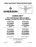
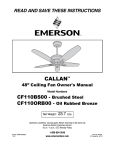
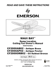
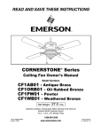
BATALIE BREEZE™
52” Wet Location
Ceiling Fan Owner's Manual
Model Numbers
CF621SW00
Satin White
CF621VNB00
Venetian Bronze
CF621VS00
Vintage Steel
Net Weight: 26.5 Lbs.
Questions, problems, missing parts: Before returning to the store call
Emerson Electric Customer Service
8 a.m. - 6 p.m., Eastern, Monday-Friday
Part No. F40BP74770000
Revision: 131113
1-800-654-3545
www.emersonfans.com
Form No. BP7477
U.L. Model No.: CF621
Table of Contents
Section
Page
6. Fan Speed and Direction . . . . . . . . . . . . . . . . . . . . . . . .12
7. Maintenance . . . . . . . . . . . . . . . . . . . . . . . . . . . . . . . . . .13
8. Accessories . . . . . . . . . . . . . . . . . . . . . . . . . . . . . . . . . . .13
9. Trouble Shooting . . . . . . . . . . . . . . . . . . . . . . . . . . . . . . .14
10. Repair Parts . . . . . . . . . . . . . . . . . . . . . . . . . . . . . . .16-17
Ceiling Fan Limited Warranty . . . . . . . . . . . . . . . . . . . . . . .19
Section
Page
Safety Instructions . . . . . . . . . . . . . . . . . . . . . . . . . . . . . . . .2
1. Unpacking Instructions . . . . . . . . . . . . . . . . . . . . . . . . .3-4
2. Electrical Requirements . . . . . . . . . . . . . . . . . . . . . . . . . .4
3. Ceiling Fan Assembly . . . . . . . . . . . . . . . . . . . . . . . . . .5-8
4. How to Hang Your Ceiling Fan . . . . . . . . . . . . . . . . . .9-10
5. How to Wire Your Ceiling Fan . . . . . . . . . . . . . . . . . .10-11
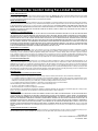
READ AND SAVE THESE INSTRUCTIONS
Safety Instructions
!
3. The outlet box and joist must be securely mounted
and capable of reliably supporting at least 50 pounds.
Use only U.L. outlet boxes listed as “Acceptable for
Fan Support of 22.7 kg. (50 lbs.) or less”, and use the
mounting screws provided with the outlet box. Most
outlet boxes commonly used for support of light
fixtures are not acceptable for fan support and may
need to be replaced. Consult a qualified electrician if
in doubt.
4. The downrod furnished with the fan provides the
minimum recommended floor to fan blade clearance
for an 8 foot ceiling.
5. The fan must be mounted with the fan blades at least
7 feet from the floor to prevent accidental contact with
the fan blades.
6. Follow the recommended instructions for the proper
method of wiring your ceiling fan. If you do not know
enough about electrical wiring, have your fan installed
by a licensed electrician.
WARNING: To reduce the risk of electrical shock, this
fan must be installed with an isolating wall control/
switch.
NOTE: This fan is suitable for use with solid-state speed
controls.
WARNING: This product is designed to use only those
parts supplied with this product and/or any accessories
designated specifically for use this product by Emerson
Electric Co. Substitution of parts or accessories not
designated for use with this product by Emerson could
result in personal injury or property damage.
WARNING: To reduce the risk of personal injury, do not
bend the blade flange when installing the blade flanges,
balancing the blades or cleaning the fan. Do not insert
foreign objects in between rotating fan blades.
WARNING: To avoid fire, shock or injury, do not use an
Emerson or any other brand of control not specifically
approved for this fan.
NOTE: All setscrews must be checked and re-tightened
where necessary before installation.
NOTE: This fan is suitable for use in wet locations when
installed in a GFCI protected branch circuit.
WARNING
TO REDUCE THE RISK OF FIRE, ELECTRICAL SHOCK,
OR INJURY TO PERSONS, OBSERVE THE
FOLLOWING:
a. Use this unit only in a manner intended by the
manufacturer. If you have questions, contact the
manufacturer.
b. Before servicing or cleaning unit, switch power off
at service panel and lock service panel
disconnecting means to prevent power from being
switched on accidentally. When the service
disconnecting means cannot be locked, securely
fasten a warning device, such as a tag, to the
service panel.
1. Read your owner’s manual carefully and keep it for
future reference.
2. Be careful of the fan and blades when cleaning,
painting, or working near the fan. Always turn off the
power to the ceiling fan before servicing.
3. Do not put anything into the fan blades while they are
turning.
4. Do not operate reversing switch until fan blades have
come to a complete stop.
Additional Safety Instructions for Installation
1. To avoid possible shock, be sure electricity is turned
off at the fuse box before wiring, and do not operate
fan without blades.
2. All wiring must be in accordance with the National
Electrical Code “ANSI/NFPA 70-2014” and Local
Electrical Codes. Use the National Electrical Code if
Local Codes do not exist. The ceiling fan must be
grounded as a precaution against possible electrical
shock. Electrical installation should be made or
approved by a licensed electrician.
DATE CODE:
The date code of this fan may be found on the box, stamped in ink on a white label. You should record
this data above and keep it in a safe place for future use.
2
U.L. Model No.: CF621
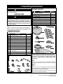
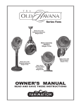
1. Unpacking Instructions
!
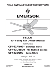
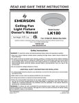
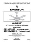
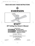
PACKAGE CONTENTS
WARNING
Do not install or use fan if any part is damaged or
missing. Call Toll-Free:
Part
A
B
C
D
E
F
G
H
I
1-800-654-3545
!
WARNING
This product is designed to use only those parts
supplied with this product and/or any accessories
designated specifically for use with this product by
Emerson Electric Co. Substitution of parts or
accessories not designated for use with this product
by Emerson Electric Co. could result in personal injury
or property damage.
Description
Fan Motor Assembly
Hanger Bracket
Hanger Ball/Downrod Assembly
Ceiling Canopy
Motor Coupler Cover
Blade Flanges
Fan Blades
Lower Housing
Switch Housing Assembly
1.1
Quantity
1
1
1
1
1
5
5
1
1
E
Check to see that you have received the following parts:
NOTE: If you are uncertain of part description, refer
to exploded view illustration.
HARDWARE CONTENTS
A
F
Part
1
Description
Threaded Studs, #8-32 x 1-1/4”
Quantity
2
2
3
Knurled Knobs, #8-32
Lockwashers, External Tooth #8
2
2
4
5
Wire Connectors
Clevis Pin
3
1
6
7
8
9
10
11
1
21
21
1
1
12
Hairpin Clip
#10-24 x 12mm Washer Head Blade Screws
16mm Flat Washers
#8-32 x 8mm Pan Head Screw
#8-32 x 8mm Flat Head Screw
1/4-20 x 14mm Pan Head Screw
with Lockwasher
Pull Chain, Coupling, & Pendant
13
Blade Balance Kit
1
1
2
3
B
C
H
D
1
1
I
G
NOTE: Place the parts from the loose parts bags in
a small container to keep them from being lost. If
any parts are missing, contact your local
retailer or catalog outlet for replacement before
proceeding.
1.2
5
4
Remove and discard the two cardboard shipping
retainers securing the motor hub in the motor housing
assembly.
6
7
11
9
8
12
1.3
10
Remove the fan assembly from the protective
plastic bag. Place the fan assembly into the upper foam
pad with the top of the motor facing up.
The upper foam pad serves as a holder for the fan
during the first stages of assembly.
13
3
emersonfans.com
Please contact 1-800-654-3545 for further assistance
U.L. Model No.: CF621
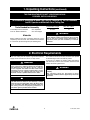
1. Unpacking Instructions (continued)
THIS FAN IS SUITABLE FOR WET LOCATIONS SUCH AS
PORCHES, PATIOS, AND DECKS.
This Manual Is Designed to Make it as Easy as Possible for You to Assemble,
Install, Operate and Maintain Your Ceiling Fan
Installed Wire Length
Up to 50 ft.
50-100 ft.
Tools Needed for Assembly
One Phillips head screwdriver
One 1/4” blade screwdriver
One stepladder
One wire stripper
!
Materials
Wire Size A.W.G.
14
12
WARNING
Before assembling your ceiling fan, refer to section on
proper method of wiring your fan (page 10). If you feel
you do not have enough wiring knowledge or
experience, have your fan installed by a licensed
electrician.
Wiring outlet box and box connectors must be of type
required by the local code. The minimum wire would be
a 3-conductor (2-wire with ground) of following size:
2. Electrical Requirements
Your new ceiling fan will require a grounded electrical
supply line of 120 volts AC, 60 Hz, 15 amp circuit.
!
The outlet box must be securely anchored and capable
of withstanding a load of at least 50 pounds.
If your fan is to replace an existing ceiling light fixture,
turn electricity off at the main fuse box at this time and
remove the existing light fixture.
WARNING
To reduce the risk of fire, electric shock, or personal
injury, mount fan to outlet box marked “Acceptable for
Fan Support of 22.7 kg. (50 lbs.) or less”, and use
screws supplied with outlet box. Most outlet boxes
commonly used for support of light fixtures are not
acceptable for fan support and may need to be
replaced. Consult a qualified electrician if in doubt.
!
!
WARNING
To avoid fire or shock, follow all wiring instructions
carefully.
Any electrical work not described in these
instructions should be done or approved by a licensed
electrician.
WARNING
Turning off wall switch is not sufficient. To avoid
possible electrical shock, be sure electricity is turned
off at the main fuse box before wiring. All wiring must
be in accordance with National and Local codes and
the ceiling fan must be properly grounded as a
precaution against possible electrical shock.
4
U.L. Model No.: CF621
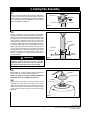
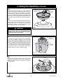
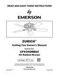
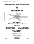
3. Ceiling Fan Assembly
3.1
PIN
HANGER BALL
Remove the hanger ball by loosening the setscrew in
the hanger ball until the ball falls freely down the
downrod (Figure 1). Remove the pin from the downrod,
then remove the hanger ball. Retain the pin and hanger
ball for reinstallation in Step 3.5.
SETSCREW
DOWNROD
Figure 1
3.2
Loosen setscrew in motor coupling if necessary.
Separate, untwist and unkink the three 80” motor leads.
Route the motor lead wires through the downrod. Align
the clevis pin holes in the downrod with the holes in the
motor coupling. Install the clevis pin and secure with
the hairpin clip (Figure 2). The clevis pin must go
through the holes in the motor coupling and the holes in
the downrod. Be sure to push the straight leg of the
hairpin clip through the hole near the end of the clevis
pin until the curved portion of the hairpin clip snaps
around the clevis pin. The hairpin clip must be properly
installed to prevent the clevis pin from working loose.
Pull on the downrod to make sure the clevis pin is
properly installed.
DOWNROD
DOWNROD
HAIRPIN
HAIRPIN
CLIP
CLIP
SETSCREW
(2)
SETSCREW
CLEVIS
PIN
CLEVIS PIN
MOTOR
MOTOR
COUPLING
COUPLING
!
WARNING
Figure 2
It is critical that the clevis pin in the motor coupling is
properly installed and the setscrews securely
tightened. Failure to verify that the pin and setscrews
are properly installed could result in the fan falling.
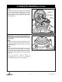
3.3
While pulling up on the downrod, securely tighten the
two setscrews in the motor coupling (Figure 3).
NOTE: The setscrews must be properly installed as
described above, or fan wobble could result.
GROMMET
COUPLING COVER
3.4
DOWNROD
SETSCREW (2)
Make sure the grommet is properly installed in the
coupling cover then slide the coupler cover on the
downrod until it rests on the motor housing. Place the
ceiling cover over the downrod. Be sure both the ceiling
cover and the coupler cover are oriented correctly
(Figure 3).
COUPLING
Figure 3
5
emersonfans.com
Please contact 1-800-654-3545 for further assistance
U.L. Model No.: CF621
3. Ceiling Fan Assembly (continued)
3.5
HANGER BALL
Reinstall the hanger ball (Figure 4) on the downrod as
follows. Route the motor leads through the downrod.
Position the pin through the two holes in the downrod
and align the ball so the pin is captured in the groove in
the top of the hanger ball. Pull the hanger ball up tight
against the pin and securely tighten the setscrew in the
hanger ball. A loose setscrew could create fan wobble.
PIN
DOWNROD
CEILING
COVER
SETSCREW
3.6
The fan comes with blue, black and white leads that are
80-inches long. Before installing the fan, measure up
approximately 6 to 9-inches above top of hanger
ball/downrod assembly. Cut off excess leads and strip
back insulation 1/2-inch from end of leads.
!
Figure 4
WARNING
It is critical that the pin in the hanger ball is properly
installed and the setscrew securely tightened. Failure
to verify that the pin and setscrew are properly
installed could result in the fan falling.
3.7
PARTIALLY
ASSEMBLED FAN
Turn fan motor assembly upside down in preparation
for mounting fan blades. Position the top and bottom
halves of the styrofoam packaging on end, with solid
styrofoam facing outward. Set side-by-side on the floor
with a six to eight-inch gap between the halves (Figure
5). Carefully place the partially assembled ceiling fan
on the styrofoam halves, with the hanger ball/downrod
assembly positioned in the gap and the fan motor
assembly resting on top of the styrofoam ends.
SOLID
STYROFOAM
FACING OUT
6" - 8"
GAP
Figure 5
3.8
SPACER ATTACHMENT
SCREW
Remove the shipping spacers and the spacer
attachment screws from the motor before installation of
blade assemblies. Discard the spacers and spacer
screws (Figure 6).
SHIPPING
SPACER
Figure 6
6
U.L. Model No.: CF621
3. Ceiling Fan Assembly (continued)
3.9
#10 - 24 x 12mm
WASHER HEAD SCREW
(4 per blade/flange)
Mount blade flanges to fan blades using four #10 - 24 x
12mm washer head screws and four 16mm flat
washers (supplied with fan) (Figure 7).
16mm FLAT WASHER
(4 per blade/flange)
NOTE: Some accessory blades available are
supplied with shorter screws. These shorter screws
MUST be used to assemble the blades to flanges.
FAN BLADE
BLADE FLANGE
Figure 7
3.10
1/4 - 20 x 14mm CAPTIVE
PAN HEAD SCREW (2)
Loosely attach one blade/flange assembly to the motor
hub by securing the two 1/4 - 20 x 14mm captive pan
head screws. Make sure the screws are NOT tightened
(Figure 8). Repeat this procedure for other four blade
assemblies.
BLADE/FLANGE ASSEMBLY (5)
Figure 8
3.11
!
Once all five blade/flange assemblies are secured to
the motor hub, proceed to tighten all the 1/4 - 20 x
14mm captive pan head screws at this time.
WARNING
To reduce the risk of personal injury, do not bend the
blade flange when installing the blade flanges,
balancing the blades or cleaning the fan. Do not insert
foreign objects in between rotating fan blades.
3.12
LOWER HOUSING
Remove one #8 - 32 x 8mm pan head screw from the
lower housing adapter plate (reserve for later use).
Loosen the other two screws to assemble the lower
housing to the lower housing adapter plate (Figure 9).
LOWER HOUSING
ADAPTER PLATE
LOOSEN TWO #8 - 32 x
8mm PAN HEAD SCREWS
REMOVE ONE #8 - 32 x
8mm PAN HEAD SCREW
3.13
Position the lower housing onto the fan motor assembly,
aligning each of the the three holes. Rotate the lower
housing to engage the two loosened screws in the two
key hole slots. Replace the #8 - 32 x 8mm pan head
screw (removed previously) and tighten all three screws
to secure the lower housing to the lower housing
adapter plate (Figure 9).
NOTE: Make sure wires are not pinched between
lower housing adapter plate and lower housing.
Figure 9
7
emersonfans.com
Please contact 1-800-654-3545 for further assistance
U.L. Model No.: CF621
3. Ceiling Fan Assembly (continued)
3.14
Engage the connector of the switch housing assembly
with the motor connector (Figure 10). The two
connectors are keyed and color-coded and must be
mated correctly (color-to-color) before they can be
engaged. Make sure the connector latch closes
properly (Figure 10).
SWITCH HOUSING
ASSEMBLY
SWITCH HOUSING
ASSEMBLY CONNECTOR
MOTOR
CONNECTOR
Figure 10
NOTE: Make sure all wires and connector are
tucked under the switch housing assembly and not
pinched between the switch housing assembly and
lower housing.
SWITCH HOUSING
ASSEMBLY
3.15
Remove the three #8 - 32 x 8mm flat head screws from
the switch housing assembly (reserve for later use) for
assembly of the switch housing assembly to the lower
housing (Figure 11).
LOWER HOUSING
3.16
#8 - 32 x 8mm FLAT
HEAD SCREW (3)
Position the switch housing assembly onto the lower
housing, aligning each of the the three holes. Replace
the three #8 - 32 x 8mm flat head screw (removed
previously) and tighten all three screws to secure the
switch housing assembly to the lower housing.
(Figure 11).
Figure 11
Please call Emerson technical support at
1-800-654-3545 if you have any questions
about installation and operation of this ceiling fan.
8
U.L. Model No.: CF621
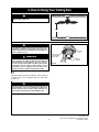
4. How to Hang Your Ceiling Fan
!
WARNING
CEILING
The fan must be hung with at least 7' of clearance from
floor to blades (Figure 12).
AT LEAST
7'
Figure 12
!
FLOOR
WARNING
The outlet box and joist must be securely mounted and
capable of supporting at least 50 lbs. Use only a U.L.
outlet box listed as “Acceptable for Fan Support of
22.7 kg. (50 lbs.) or less”.
!
OUTLET
BOX
TWO SCREWS
SUPPLIED WITH
OUTLET BOX
WARNING
To reduce the risk of fire, electric shock, or personal
injury, mount fan to outlet box marked “Acceptable for
Fan Support of 22.7 kg. (50 lbs.) or less”, and use
screws supplied with outlet box. Most outlet boxes
commonly used for support of light fixtures are not
acceptable for fan support and may need to be
replaced. Consult a qualified electrician if in doubt.
TAB
HANGER
BRACKET
Figure 13
4.1
Securely attach the hanger bracket to the outlet box
using the two screws supplied with the outlet box.
(Figure 13.)
!
WARNING
Hanger bracket must seat firmly against outlet box. If
the outlet box is recessed, remove wall board until
bracket contacts box. If bracket and/or outlet box are
not securely attached, the fan could wobble or fall.
9
emersonfans.com
Please contact 1-800-654-3545 for further assistance
U.L. Model No.: CF621
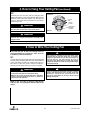
4. How to Hang Your Ceiling Fan (continued)
4.2
NOTE: CEILING COVER, SUPPLY WIRES AND FAN WIRES OMITTED
FOR CLARITY.
Carefully lift the fan and seat the hanger ball/
downrod assembly on the hanger bracket that was just
attached to the outlet box (Figure 14). Be sure the
groove in the ball is lined up with tab on the hanger
bracket (Figure 13).
!
OUTLET
BOX
HANGER
BRACKET
WARNING
HANGER BALL/
DOWNROD
ASSEMBLY
Failure to seat tab in groove could cause damage to
electrical wires and possible shock or fire hazard.
Figure 14
!
WARNING
To avoid possible fire or shock, do not pinch wires
between the hanger ball/downrod assembly and
hanger bracket.
5. How to Wire Your Ceiling Fan
If you feel that you do not have enough electrical
wiring knowledge or experience, have your fan
installed by a licensed electrician.
!
This product is designed to use only those parts
supplied with this product and/or any accessories
designated specifically for use with this product by
Emerson Electric Co. Substitution of parts or
accessories not designated for use with this product
by Emerson Electric Co. could result in personal injury
or property damage.
5.1
Connect the green grounding lead from the hanger ball
and the green grounding lead from the hanger bracket
to the grounding conductor of supply (this may be a
bare wire or wire with green colored insulation).
Securely connect wires with wire connectors supplied.
!
WARNING
!
WARNING
WARNING
Check to see that all connections are tight, including
ground, and that no bare wire is visible at the wire
connectors, except for the ground wire. Do not
operate fan until blades are in place. Noise and fan
damage could result.
To avoid possible electrical shock, be sure electricity
is turned off at the main fuse box before wiring.
NOTE: If you are not sure if the outlet box is grounded,
contact a licensed electrician for advice, as it must be
grounded for safe operation.
NOTE: If you are using an Emerson Light Fixture
with your fan, see Light Fixture Owner’s Manual for
wiring.
10
U.L. Model No.: CF621
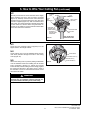
5. How to Wire Your Ceiling Fan (continued)
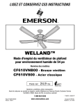
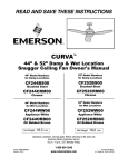
5.2
GROUND
WIRE
Securely connect the fan motor white wire to the supply
white (neutral) wire using wire connector supplied
(Figure 15). Securely connect the fan motor black wire
and blue wire to the supply black (hot) wire using wire
connector supplied (Figure 15). After connections have
been made, turn leads upward and carefully push leads
into the outlet box, with the white and green leads on
one side of the outlet box and the blue and black leads
on the other side of the outlet box.
BLACK
FAN WIRE
BLUE FAN WIRE
LISTED
WIRE
CONNECTOR (3)
WHITE SUPPLY
(NEUTRAL)
GREEN WIRE
(GROUND) FROM
HANGER BRACKET
GREEN WIRE
(GROUND) FROM
HANGER BALL
Figure 15
WHITE FAN WIRE
BLACK SUPPLY
(HOT)
NOTE: CEILING COVER
OMITTED FOR CLARITY.
5.3
Screw the two threaded studs (supplied) into the
tapped holes in the hanger bracket.
5.4
Lift the ceiling cover up to the threaded studs and turn
until studs protrude through the holes in the ceiling
cover (Figure 16).
CEILING COVER
THREADED STUDS (2)
LOCKWASHERS (2)
5.5
KNURLED KNOBS (2)
Secure the ceiling cover in place by sliding lockwashers
over the threaded studs and installing the two knurled
knobs (supplied). (Figure 16). Tighten the knurled
knobs securely until the ceiling cover fits snugly against
the ceiling and the hole in the ceiling cover is clear of
the downrod. Your fan is now wired to be turned on and
off from the fan switch.
!
Figure 16
WARNING
To avoid possible fire or shock, make sure that the
electrical wires are completely inside the outlet box and
not pinched between the ceiling cover and the ceiling.
11
emersonfans.com
Please contact 1-800-654-3545 for further assistance
U.L. Model No.: CF621
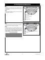
6. Fan Speed and Direction
6.1
Assembly of the ceiling fan is now complete. Restore
electrical power to the branch circuit at the fuse box or
breaker panel.
6.2
Connect the fan speed pull chain to the wood pendant
with pull chain. (Figure 17).
FAN SPEED
PULL CHAIN
PULL CHAIN COUPLING
PULL CHAIN
WOOD PENDANT
Figure 17
6.3
All fans are shipped from the factory with the reversing
switch positioned to circulate air downward.
6.4
If airflow is desired in the opposite direction, turn the
fan off and wait for the blades to stop turning. Then
slide the reversing switch, located on top of the fan
motor assembly, to the opposite position (Figure 18)
and turn the fan on again. The blades will turn in the
opposite direction and reverse the airflow.
Season
Summer
Winter
FAN SPEED PULL
CHAIN
Reverse Switch Information
Rotation Direction
Switch Position
Counter-Clockwise
Right
Clockwise
Left
REVERSE SWITCH
Figure 18
12
U.L. Model No.: CF621
7. Maintenance
IMPORTANT CARE INSTRUCTIONS
for your Ceiling Fan
!
WARNING
Do not use water when cleaning your ceiling fan. It
could damage the motor or the blades and create the
possibility of an electrical shock.
Periodic cleaning of your new ceiling fan is the only
maintenance that is needed.
When cleaning, use only a soft brush or lint free cloth to
avoid scratching the finish.
Abrasive cleaning agents are not required and should
be avoided to prevent damage to finish.
8. Accessories
1. Ceiling Fan/Light Controls (see store or catalog).
2. Downrod Extension Kits (see store or catalog).
3. Ceiling Fan Light Kits (see store or catalog).
!
!
WARNING
This product is designed to use only those parts
supplied with this product and/or any accessories
designated specifically for use with this product by
Emerson Electric Co. Substitution of parts or
accessories not designated for use with this product
by Emerson Electric Co. could result in personal injury
or property damage.
WARNING
The use of any other control not specifically approved
for this fan could result in fire, shock and personal
injury.
13
emersonfans.com
Please contact 1-800-654-3545 for further assistance
U.L. Model No.: CF621
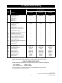
9. Trouble Shooting
!
WARNING: FOR YOUR OWN SAFETY TURN OFF POWER AT FUSE BOX OR CIRCUIT BREAKER BEFORE
TROUBLE SHOOTING YOUR FAN.
TROUBLE
1. Fan will not start.
PROBABLE CAUSE
SUGGESTED REMEDY
1. Fuse or circuit breaker blown.
1. Check main and branch circuit fuses or circuit
breakers.
2. Loose power line connections to the fan,
or loose switch wire connections in the
2. Check line wire connections to fan and switch
wire connections in the switch housing.
switch housing.
!
3. Reversing switch in neutral position.
3. Make sure reversing switch position is all the
way to one side.
2. Fan sounds noisy. 1. Blades not attached to fan.
1. Attach blades to fan before operating.
2. Loose screws in motor housing.
2. Check to make sure all screws in motor housing
are snug (not over-tight).
3. Wire connectors inside switch housing
rattling.
3. Check to make sure wire connectors in switch
housing are not rattling against each other or
against the interior wall of the switch housing.
!
3. Fan wobbles
excessively.
WARNING: Make sure main power is
turned OFF.
WARNING: Make sure main power is
turned OFF.
4. Screws holding blades to flywheel
are loose.
4. Tighten screws securely.
1. Setscrew in motor coupling is loose.
1. Tighten both setscrews securely in the motor
coupling.
2. Setscrew in hanger ball/downrod
assembly is loose.
2. Tighten the setscrew in the hanger ball/
downrod assembly.
3. Screws securing fan blades to
flywheel are loose.
3. Check to be sure screws which attach the fan
blades to the motor are tight.
4. Hanger bracket and/or ceiling outlet
box is not securely fastened.
4. Tighten the hanger bracket screws to the outlet
box, and/or secure outlet box.
5. Fan blades out of balance.
5. Interchanging an adjacent (side-by-side) blade
pair can redistribute the weight and result in
smoother operation.
14
U.L. Model No.: CF621
Notes
15
emersonfans.com
Please contact 1-800-654-3545 for further assistance
U.L. Model No.: CF621
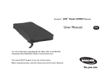
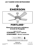
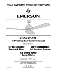
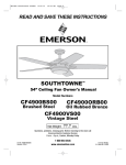
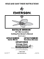
10. Repair Parts
2
1
3
6
16
15
17
7
8
18
5
4
9
23
10
20
22
11
13
19
21
12
14
16
U.L. Model No.: CF621
10. Repair Parts Listing
Wet Model Numbers
Key
No.
CF621SW00
CF621VNB00
CF621VS00
761655-92
761655-89
761655-93
1
2
3
Hanger Ball Assembly,
Consisting of:
Hanger Bracket
Hanger Ball
Downrod (4.5”)
—
—
—
—
—
—
—
—
—
*
4
5
6
7
Parts Bag Containing:
Pin, Clevis (1)
Clip, Hairpin (1)
Threaded Stud, #8 - 32 x 1-1/4” (2)
Lockwasher, External Tooth #8 (2)
764208-1
—
—
—
—
764208
—
—
—
—
764208
—
—
—
—
8
9
Knurled Knob, #8 - 32 (2)
Screw, Washer Head, #10 - 24 x 12mm (21)
—
—
—
—
—
—
10
11
12
Flat Washer, 16mm (21)
Screw, Pan Head, #8 - 32 x 8mm (1)
Screw, Flat Head, #8 - 32 x 8mm (1)
—
—
—
—
—
—
—
—
—
13
Screw, Pan Head, 1/4 - 20 x 14mm
14
15
with Lockwasher (1)
Pendant with Pull Chain and Coupling (1)
Wire Connector (3)
—
—
—
—
—
—
—
—
—
16
Balancing Kit (1)
—
—
—
17
18
Canopy, Ceiling (1)
Motor Coupling Cover (1)
764199-SW
764032-SW
764199-VNB
764032-VNB
764199-VS
764032-VS
19
20
Wiring Harness (1)
Lower Housing (1)
764204-1
764203-SW
764204
764203-VNB
764204
764203-VS
21
22
23
Switch Housing (1)
Blade Flanges (set of 5)
Fan Blades (set of 5)
Owner's Manual
764207-SW
764205-SW
B63SWH
BP7477
764207-VNB
764205-VNB
B63ASW
BP7477
764207-VS
764205-VS
B63ASW
BP7477
*
—
Description
Before discarding packaging material, be certain all parts have been removed.
HOW TO ORDER REPAIR PARTS
WHEN ORDERING REPAIR PARTS, ALWAYS GIVE THE FOLLOWING INFORMATION:
• PART NUMBER
• PART DESCRIPTION
• NAME OF ITEM
• MODEL NUMBER
The model number of your Fan will be found on a label attached to the top housing.
For repair parts, phone 1-800-654-3545.
17
emersonfans.com
Please contact 1-800-654-3545 for further assistance
U.L. Model No.: CF621
Notes
18
U.L. Model No.: CF621
Emerson Air Comfort Ceiling Fan Limited Warranty
What The Limited Warranty Covers:
This limited warranty is offered by Air Comfort Products division of Emerson Electric Co. ("Emerson" "we" or "us") located at the address stated below to the original
retail purchaser ("you" or "your") of an Emerson Air Comfort Ceiling Fan product ("Emerson Ceiling Fan") and covers the motor and the other components and
accessories of the Emerson Ceiling Fan against all defects in workmanship and materials.
What The Period Of Coverage Is:
This limited warranty will cover the Emerson Ceiling Fan motor for the expected lifetime of your Emerson Ceiling Fan (when operated in accordance with your Owner's
Manual or other instructions provided by Emerson to you with the Emerson Ceiling Fan). All other components and accessories of the Emerson Ceiling Fan are covered
by this limited warranty for a period of one (1) year from its date of original retail purchase. ANY IMPLIED WARRANTY, INCLUDING WITHOUT LIMITATION, ANY
IMPLIED WARRANTY OF MERCHANTABILITY OR FITNESS FOR A PARTICULAR PURPOSE THAT IS AVAILABLE TO YOU UNDER THE LAWS OF YOUR STATE OR
PROVINCE SHALL COVER THE MOTOR FOR THE EXPECTED LIFETIME OF THE MOTOR (SUBJECT TO PROPER USE), AND FOR ONE YEAR WITH RESPECT TO
COMPONENTS AND ACCESSORIES.
No Other Express or Implied Warranty Applies:
THE LIMITED WARRANTIES PROVIDED ABOVE ARE THE SOLE AND EXCLUSIVE WARRANTIES PROVIDED BY EMERSON TO YOU FOR YOUR EMERSON CEILING
FAN, AND ARE IN LIEU OF ALL OTHER WARRANTIES, WRITTEN OR ORAL, EXPRESS OR IMPLIED, WHETHER ARISING BY OPERATION OF LAW OR OTHERWISE,
WHETHER OR NOT THE PURPOSE HAS BEEN DISCLOSED AND WHETHER OR NOT THE EMERSON CEILING FAN HAS BEEN SPECIFICALLY DESIGNED OR
MANUFACTURED FOR YOUR USE OR PURPOSE. EMERSON HEREBY DISCLAIMS ANY AND ALL IMPLIED WARRANTIES, INCLUDING WITHOUT LIMITATION,
IMPLIED WARRANTIES OF MERCHANTABILITY OR FITNESS FOR A PARTICULAR PURPOSE FOR COMPONENTS AND ACCESSORIES AS OF THE EXPIRATION OF THE
ONE YEAR WARRANTY PERIOD FOR SUCH COMPONENTS AND ACCESSORIES. IMPLIED WARRANTIES OF MERCHANTABILITY OR FITNESS FOR A PARTICULAR
PURPOSE FOR THE MOTOR PORTION OF THE EMERSON CEILING FAN ARE LIKEWISE DISCLAIMED BY EMERSON AT SUCH TIME THAT THE EXPECTED LIFETIME
OF THE EMERSON CEILING FAN UNDER NORMAL USAGE HAS BEEN REACHED. EXCLUSIONS OR LIMITATIONS OF IMPLIED WARRANTIES MAY VARY FROM
STATE TO STATE AND PROVINCE TO PROVINCE SO THE ABOVE LIMITATIONS MAY NOT APPLY TO YOU.
What We Will Do To Correct Problems:
If during the one (1) year warranty period the motor or any component or accessory of your Emerson Ceiling Fan is defective in materials or workmanship, or if during
the expected lifetime of the Emerson Ceiling Fan (when used in accordance with the User Manual or other instructions) the motor is defective in materials or
workmanship, you must contact Emerson during the applicable warranty period. If the defect is covered by warranty, Emerson will repair or replace the defective
motor, component or other accessory at no charge to you. If repair of the motor, component or accessory is not practical or possible within a reasonable time and no
replacement Emerson Ceiling Fan can be provided, Emerson will refund to you the actual purchase price of your Emerson Ceiling Fan. We will ship the repaired or the
replacement Emerson Ceiling Fan to you at no charge, but you are responsible for all costs of removal and reinstallation of your Emerson Ceiling Fan.
How You Can Receive Warranty Service:
You must be the original retail purchaser and have proof of your purchase of the Emerson Ceiling Fan to obtain your remedy under this limited warranty. You can
return your Emerson Ceiling Fan to your place of purchase, or you can call Emerson Customer Service at 1-800-237-6511 to obtain a return authorization and service
identification tag. In order for us to confirm that your Emerson Ceiling Fan is still under warranty, please retain your receipt or other proof of purchase and have that
information readily available when returning your Emerson Ceiling Fan to your place of purchase, or upon calling Emerson Customer Service. If you call Emerson
Customer Service, prior to your call please be prepared to provide all model numbers shown on your Emerson Ceiling Fan. Once we have processed your return
authorization request, we will provide you with a postage paid return label which should be affixed to the Emerson Ceiling Fan package you ship to the address listed at
the end of this limited warranty. The return label will be sent to the mailing address you provide to us by phone.
What Is Not Covered:
This limited warranty does not extend to and expressly excludes:
• The glass globes and light bulbs of your Emerson Ceiling Fan,
• Loss or damage to the motor or any component or accessory caused by normal wear and tear, rather than due to defects in materials or workmanship,
• Loss or damage resulting from conditions beyond our reasonable control, including without limitation, repairs not made at our factory or authorized service center,
use of parts or accessories not provided to you as part of this warranty by our factory or authorized service center, mishandling, unreasonable use, misuse, abuse,
modifications or other damage caused by you or a third party to your Emerson Ceiling Fan while not in our possession,
• Loss or damage resulting from improper installation, or other failure to comply with instructions in your Owner's Manual.
This limited warranty is deemed null and void upon the occurrence of either of the following events:
• You cease to own the Emerson Ceiling Fan product, or
• The Emerson Ceiling Fan is moved from its original point of installation.
This limited warranty is only valid within the 50 United States, the District of Columbia, and Canada. No other written or oral warranties apply, and no employee, agent,
dealer or other person is authorized to give any warranties on behalf of Air Comfort Products or Emerson Electric Co.
Limitation of Liability
REPAIR, REPLACEMENT OR A REFUND ARE THE EXCLUSIVE REMEDIES AVAILABLE TO YOU UNDER THIS LIMITED WARRANTY. TO THE EXTENT PERMITTED BY
LAW, IN NO EVENT SHALL EMERSON OR ANY EMERSON AUTHORIZED DEALER BE LIABLE FOR ANY INCIDENTAL, SPECIAL, INDIRECT, OR CONSEQUENTIAL
DAMAGES, INCLUDING ANY ECONOMIC LOSS, WHETHER RESULTING FROM NONPERFORMANCE, USE, MISUSE OR INABILITY TO USE THE EMERSON CEILING
FAN OR FOR THE NEGLIGENCE OF EMERSON OR AN EMERSON AUTHORIZED DEALER. EMERSON SHALL NOT BE LIABLE FOR DAMAGES CAUSED BY DELAY IN
PERFORMANCE AND IN NO EVENT, REGARDLESS OF THE FORM OF THE CLAIM OR CAUSE OF ACTION (WHETHER BASED IN CONTRACT, INFRINGEMENT,
NEGLIGENCE, STRICT LIABILITY, OTHER TORT OR OTHERWISE), SHALL EMERSON'S OR ANY EMERSON AUTHORIZED AGENT'S LIABILITY TO YOU OR ANY
INDIVIDUAL USING THE EMERSON CEILING FAN EXCEED THE PRICE PAID BY THE ORIGINAL OWNER FOR THE EMERSON CEILING FAN. The term "consequential
damages" shall include, but not be limited to, loss of anticipated profits, business interruption, loss of use or revenue, cost of capital or loss or damage to property or
equipment.
How State and Provincial Law Relates To The Warranty:
Some states and provinces do not allow the exclusion or limitation of incidental or consequential damages so the above exclusion or limitation may not apply to you.
This limited warranty gives you specific legal rights, and you may also have other rights which vary from state to state or province to province.
19
emersonfans.com
Please contact 1-800-654-3545 for further assistance
U.L. Model No.: CF621
Air Comfort Products
DIVISION OF EMERSON ELECTRIC CO.
8100 W. Florissant • St. Louis, MO 63136
Questions, problems, missing parts: Before returning to the store call
Emerson Electric Customer Service
8 a.m. - 6 p.m., Eastern, Monday-Friday
1-800-654-3545
www.emersonfans.com
Retain this manual for future use.
Part No. F40BP74770000
Revision: 131113
Printed in China
11/13
Form No. BP7477
U.L. Model No.: CF621