1
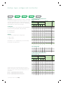
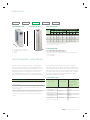
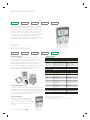
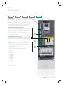
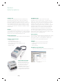
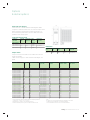
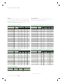
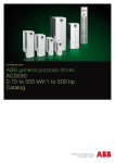
Low voltage AC drives
ABB standard drives
ACS550
0.75 to 355 kW / 1 to 500 hp
Catalog
Selecting and ordering your drive
Build up your own ordering code using the type code
key below or contact your local ABB drives sales
office and let them know what you want. Use page 3
as a reference section for more information.
Type code:
Product series
Rating and types
Voltages
Construction
Dimensions
Options
2 ABB standard drives ACS550 | Catalog
ACS550
-
01
-
03A3
-
4
+
B055
Contents
ABB standard drives, ACS550
ABB standard drives
Features, advantages and benefits
4
4
Technical data
5
Ratings, types, voltages and construction
6
Dimensions
7
Electromagnetic compatibility
7
Assistant control panel
8
Options
8
Options
8
How to select options
8
Basic control panel
8
Relay output extension option module
9
Plug-in fieldbus module
9
FlashDrop tool
10
SREA-01 Ethernet adapter
10
DriveWindow Light
10
Brake units and choppers
11
Output chokes
11
Cooling and fuses
12
Cooling
12
Fuse connections
12
Control connections
13
Services
14
Catalog | ABB standard drives ACS550 3
ABB standard drives
ACS550
-
01
-
03A3
-
4
ABB standard drives
ABB standard drives are simple to buy, install, configure
and use, saving considerable time. They are widely available
through ABB channel partners, hence the use of the term
standard. The drives have common user and process
interfaces with fieldbuses, common software tools for sizing,
commissioning, maintenance and common spare parts.
Applications
ABB standard drives can be used in a wide range of
industries. Typical applications include pump, fan and
constant torque use, such as conveyors. ABB standard
drives are ideal in those situations where there is a need
for simplicity to install, commission and use and where
customizing or special product engineering is not required.
+
B055
Highlights
− FlashDrop tool
− Intuitive use with assistant control panel
− Swinging choke for superior harmonic reduction
− Vector control
− Coated boards for harsh environments
− Built-in category C2 EMC filter (1st environment) as
standard
− Flexible fieldbus system with built-in Modbus and numerous
internally mountable fieldbus adapters
− UL, cUL, CE, C-Tick and GOST R approved
− RoHS compliant
Feature
Advantage
Benefit
Energy efficiency
Several counters to illustrate saved energy (kWh), carbondioxide
Shows direct impact on energy bill and helps control
counters
emissions (CO2) and cost in local currency.
operational expenditure (OPEX).
Load analyzer
Load analyzer saves process data, such as current and
Optimized dimensioning of the drive, motor and
torque values, which can be used to analyze the process
process.
and dimensioning of the drive and motor.
FlashDrop tool
Faster and easier drive set up and commissioning
Patented, fast, safe and trouble-free parametrization
method without electricity
Assistant control panel
Two soft-keys, function of which changes according to the state
Easy commissioning
of the panel
Built-in help function via dedicated button
Fast set-up
Real-time clock, allows timed tracing of faults and setting of
Easier configuration
parameters to activate at various times of day
Rapid fault diagnosis
Changed parameters -menu
Quick access to recent parameter changes
Commissioning
PID controller, real-time clock, serial communications assistant,
Easy set up of parameters
assistants
drive optimizer, start-up assistant
Maintenance assistant
Monitors consumed energy (kWh), running hours or motor rotation
Takes care of preventative maintenance of drive, the
motor or run application
Intuitive features
Noise optimisation
Increases switching frequency of drive when drive temperature is
Considerable motor noise reduction
reduced
Choke
Controlled cooling fan: the drive is cooled only when necessary
Reduces inverter noise and improves energy efficiency
Patented swinging choke - matches the right inductance to the
Reduces total harmonic distortion (THD) emissions up
right load, thereby suppressing and reducing harmonics
to 25%
Vector control
Improved motor control performance
Enables wider range of applications
Built-in EMC filter
Category C2 (1st environment) and category C3 (2nd environment)
No need for additional external filtering
RFI filters as standard
Brake chopper
Built-in up to 11 kW
Reduced cost
Connectivity
Built-in Modbus using EIA-485
Reduced cost
Simple to install:
Reduced installation time
Easy connection of cables
Secure cable connections
Easy connection to external fieldbus systems through multiple I/Os
and plug-in options
Mounting template
Supplied separately with unit
Quick and easy to mark mounting screw holes on
installation surface
RoHS compliant
ACS550 drives comply with the EU’s RoHS 2002/95/CE Directive
restricting the use of certaing hazardous substances
4 ABB standard drives ACS550 | Catalog
Environmentally friendly product
Technical data
ACS550
-
01
-
03A3
-
Mains connection
4
+
B055
Programmable control connections
Voltage and
3-phase, 380 to 480 V, +10/ -15%, 0.75 to 355 kW
Two analog inputs
power range
3-phase, 208 to 240 V, +10/ -15%, 0.75 to 75 kW
Voltage signal
0 (2) to 10 V, R in > 312 kΩ single-ended
Auto-identification of input line
Current signal
0 (4) to 20 mA, R in = 100 Ω single-ended
Frequency
48 to 63 Hz
Potentiometer
10 V ± 2% max. 10 mA, R < 10 kΩ
Power factor
0.98
reference value
Motor connection
Maximum delay
12 to 32 ms
Voltage
3-phase, from 0 to U SUPPLY
Resolution
0.1%
Frequency
0 to 500 Hz
Accuracy
±1%
Continuous loading
Rated output current I 2N
Two analog outputs
0 (4) to 20 mA, load < 500 Ω
Accuracy
±3%
Auxiliary voltage
24 V DC ±10%, max. 250 mA
Six digital inputs
12 to 24 V DC with internal or external supply,
capability
(constant torque at a max
ambient temperature of
40 0C)
Overload capacity
At normal use 1.1 x I 2N for 1 minute every
(at a max. ambient
temperature of 40 0C)
10 minutes
Input impedance
2.4 kΩ
At heavy-duty use 1.5 x I2hd for 1 minute every 10
Maximum delay
5 ms ± 1 ms
minutes
Three relay outputs
PNP and NPN
Always 1.8 x I2hd for 2 seconds every 60 seconds
Maximum switching
Switching frequency
Default 4 kHz
voltage
Selectable
1 kHz, 2 kHz, 4 kHz, 8 kHz, 12 kHz
Maximum switching
Acceleration time
0.1 to 1800 s
current
Deceleration time
0.1 to 1800 s
Maximum continuous
Speed control
current
250 V AC/30 V DC
6 A/30 V DC; 1500 V A/230 V AC
2 A rms
Open loop
20% of motor nominal slip
Serial communication
Closed loop
0.1% of motor nominal speed
EIA-485
Open loop
< 1% s with 100% torque step
Product compliance
Closed loop
0.5% s with 100% torque step
Low Voltage Directive 2006/95/EC
Torque control
Modbus protocol
Machinery Directive 2006/42/EC
Open loop
< 10 ms with nominal torque
Closed loop
< 10 ms with nominal torque
Open loop
±5% with nominal torque
Closed loop
±2% with nominal torque
Environmental limits
EMC Directive 2004/108/EC
Quality assurance system ISO 9001
Environmental system ISO 14001
UL, cUL, CE, C-Tick and GOST R approvals
RoHS compliant
Ambient temperature
-15 to 50 oC
No frost allowed. From 40 to 50 °C with derating.
Altitude
Rated current available at 0 to 1000 m
Output current
reduced by 1% per 100 m over 1000 to 2000 m
Relative humidity
5 to 95%, no condensation allowed
Degree of protection IP21 or IP54 (≤ 160 kW)
Enclosure colour
NCS 1502-Y, RAL 9002, PMS 420 C
Contamination
IEC 721-3-3
levels
No conductive dust allowed
Class 1C2 (chemical gases),
Transportation
Class 1S2 (solid particles)
Class 2C2 (chemical gases),
Storage
Class 2S2 (solid particles)
Class 3C2 (chemical gases),
Operation
Class 3S2 (solid particles)
Catalog | ABB standard drives ACS550 5
Ratings, types, voltages and construction
ACS550
-
01
-
03A3
-
Type code
Drive’s type code (shown above and in column 7 of the tables
on the right side) identifies your drive by construction, current
rating and voltage range. Once you have selected the type
code, the frame size (column 8) can be used to determine the
drives dimensions, shown on the next page.
Construction
“01” within the type code (shown above) varies depending on
the drive mounting arrangement, and power rating.
01 = wall-mounted
02 = free-standing
Voltages
The ACS550 is available in two voltage ranges:
4 = 380 to 480 V
2 = 208 to 240 V
Insert either “4” or “2”, depending on your chosen voltage,
into the type code shown above.
4
+
B055
3-phase supply voltage 380 to 480 V
Wall-mounted units
Ratings
Normal use
Type code
Heavy-duty use
Frame
size
PN
PN
I2N
P hd
P hd
I 2hd
kW
1.1
1.5
2.2
3
4
5.5
7.5
11
15
18.5
22
30
37
45
55
75
90
110
132
160
hp
1.5
2
3
4
5.4
7.5
10
15
20
25
30
40
50
60
100
125
150
150
200
200
A
3.3
4.1
5.4
6.9
8.8
11.9
15.4
23
31
38
45
59
72
87
125
157
180
205
246
290
kW
0.75
1.1
1.5
2.2
3
4
5.5
7.5
11
15
18.5
22
30
37
45
55
75
90
110
132
hp
1
1.5
2
3
4
5.4
7.5
10
15
20
25
30
40
60
75
100
125
125
150
200
A
2.4
3.3
4.1
5.4
6.9
8.8
11.9
15.4
23
31
38
45
59
72
96
125
156
162
192
246
ACS550-01-03A3-4
ACS550-01-04A1-4
ACS550-01-05A4-4
ACS550-01-06A9-4
ACS550-01-08A8-4
ACS550-01-012A-4
ACS550-01-015A-4
ACS550-01-023A-4
ACS550-01-031A-4
ACS550-01-038A-4
ACS550-01-045A-4
ACS550-01-059A-4
ACS550-01-072A-4
ACS550-01-087A-4
ACS550-01-125A-4
ACS550-01-157A-4
ACS550-01-180A-4
ACS550-01-195A-4
ACS550-01-246A-4
ACS550-01-290A-4
R1
R1
R1
R1
R1
R1
R2
R2
R3
R3
R3
R4
R4
R4
R5
R6
R6
R6
R6
R6
250
350
400
450
500
302
414
477
515
590
ACS550-02-368A-4
ACS550-02-486A-4
ACS550-02-526A-4
ACS550-02-602A-4
ACS550-02-645A-4
R8
R8
R8
R8
R8
Free-standing units
200
250
280
315
355
300
400
450
500
500
368
486
526
602
645
160
200
250
280
315
3-phase supply voltage 208 to 240 V
Wall-mounted units
Ratings
Normal use
Normal use vs heavy-duty use. For the majority of pump, fan and conveyor
applications, select “Normal use” figures. For high overload requirements, select
“Heavy-duty use” figures. If in doubt contact your local ABB sales office or your
drives distributor.
PN for kW
PN for hp
Phd for kW
Phd for hp
= Typical motor power in 400 V at normal use
= Typical motor power in 460 V at normal use
= Typical motor power in 400 V at heavy-duty use
= Typical motor power in 460 V at heavy-duty use
6 ABB standard drives ACS550 | Catalog
Type code
Heavy-duty use
PN
PN
I2N
P hd
Phd
I 2hd
kW
0.75
1.1
1.5
2.2
4.0
5.5
7.5
11.0
15.0
18.5
22.0
30.0
37.0
45.0
55.0
75.0
hp
1.0
1.5
2.0
3.0
5.0
7.5
10.0
15.0
20.0
25.0
30.0
40.0
50.0
60.0
75.0
100
A
4.6
6.6
7.5
11.8
16.7
24.2
30.8
46.2
59.4
74.8
88.0
114
143
178
221
248
kW
0.75
0.75
1.1
1.5
3.0
4.0
5.5
7.5
11.0
15.0
18.5
22.0
30.0
37.0
45.0
55.0
hp
0.8
1.0
1.5
2.0
3.0
5.0
7.5
10.0
15.0
20.0
25.0
30.0
40
50
60
75
A
3.5
4.6
6.6
7.5
11.8
16.7
24.2
30.8
46.2
59.4
74.8
88.0
114
150
178
192
Frame
size
ACS550-01-04A6-2
ACS550-01-06A6-2
ACS550-01-07A5-2
ACS550-01-012A-2
ACS550-01-017A-2
ACS550-01-024A-2
ACS550-01-031A-2
ACS550-01-046A-2
ACS550-01-059A-2
ACS550-01-075A-2
ACS550-01-088A-2
ACS550-01-114A-2
ACS550-01-143A-2
ACS550-01-178A-2
ACS550-01-221A-2
ACS550-01-248A-2
R1
R1
R1
R1
R1
R2
R2
R3
R3
R4
R4
R4
R6
R6
R6
R6
Dimensions
ACS550
-
01
-
Wall-mounted drives
03A3
-
4
Free-standing drives
+
B055
Wall-mounted units
Frame Dimensions and weights
IP21 / UL type 1
IP54 / UL type 122)
size
H1
H2
W
D
Weight H
W
D
Weight
H2
H1
R1
R2
R3
R4
R5
R6
H1
1)
2)
3)
D
mm
369
469
583
689
736
8881)
mm
330
430
490
596
602
700
mm
125
125
203
203
265
302
mm
212
222
231
262
286
400
kg
6.5
9
16
24
34
69
mm
461
561
629
760
775
924 3)
mm
213
213
257
257
369
410
mm
234
245
254
284
309
423
kg
8
11
17
26
42
86
ACS550-x1-246A-4 and ACS550-01-290A-4: 979 mm
UL Type 12 not available for ACS550-01-290A-4
ACS550-01-290A-4 : 1119 mm
W
Free-standing units
H1
H2
W
D
= Height with cable connection box
= Height without cable connection box
= Width
= Depth
D
W
R8
1)
2024 n/a
347 1) 617 1) 230
The dimensions apply to bookshelf mounting. In flat type mounting the width and
depth change places.
n/a = not applicablez
Electromagnetic compatibility
The EMC product standard (EN 61800-3 + Amendment
A11(2000)) covers the specific EMC requirements stated
for drives (tested with motor and cable) within the EU. The
new revision of 61800-3 (2004) product standard can be
applied from now on, but latest from 1st October 2007.
EMC standards such as EN 55011, or EN 61000-6-3/4,
apply to industrial and household equipments and systems
including drive component inside. Drive units complying
with requirements of EN 61800-3 are always complient with
comparable categories in EN 55011 and EN 61000-6-3/4, but
not necessarily vice versa. EN 55011 and EN 61000-6-3/4 do
not specify cable length nor require a motor to be connected
as a load. The emission limits are comparable according to
the following table, EMC standards.
EMC standards in general
EMC according to EN61800-3
EN 61800-3/A11 (2000),
EN 61800-3 (2004),
EN 55011, product
1 st environment restricted distribution for frame sizes R3, R4 with
product standard
product standard
family standard for
75 m motor cables and for frame sizes R1, R2, R5, R6 with 100 m motor
industrial, scientific
cables as standard.
and medical (ISM)
2 nd environment unrestricted distribution for frame sizes R1 to R4 with
equipment
300 m motor cables and for frame sizes R5 to R8 with 100 m motor
1 environment,
cables as standard.
unrestricted distribution
These cable lengths are for EMC purposes only. Operational cable
lengths are available in the output choke selection table on page 11.
For longer motor cable lengths, external EMC filters are available on
request.
st
1 st environment,
Category C1
Category C2
restricted distribution
2 nd environment,
Group 1
Class A
Category C3
unrestricted distribution
2 nd environment,
Group 1
Class B
Group 2
Class A
Category C4
Not applicable
restricted distribution
Catalog | ABB standard drives ACS550 7
Assistant control panel
ACS550
-
01
-
03A3
-
4
+
B055
4
+
B055
The assistant control panel, which is delivered as standard,
features a multilingual alphanumeric display for easy drive
programming. The control panel has various assistants and
an built-in help function to guide the user. It includes a real
time clock, which can be used during fault logging and in
controlling the drive, such as start/stop. The control panel
can be used for copying parameters for back up or for
downloading them to another drive. A large graphical display
and soft keys make it extremely easy to navigate.
Options
Control interfaces
ACS550
-
01
-
03A3
-
Panel mounting kits
To attach the control panel to the outside of a larger enclosure,
two panel mounting kits are available. A simple and costefficient installation is possible with the ACS/H-CP-EXT kit,
while the OPMP-01 kit provides a more user-friendly solution,
including a panel platform that enables the panel to be
removed in the same way as a drive-mounted panel. The panel
mounting kits include all hardware required, including 3 m
extension cables and installation instructions.
Available options
Protection class
B055
IP54
Control panel
0J400
If no control panel is required
J404
Basic control panel
- 1)
Panel mounting kit
- 1)
Panel holder mounting kit
I/O options2)
L511
Relay output extension
Control option2)
- 1)
Encoder
Fieldbus3)
K451
DeviceNet
K452
LonWorks
K454
Profibus DP
K457
CANopen
K462
ControlNet
- 1)
- 1)
- 1)
- 1)
- 1)
How to select options
The options shown in the table are available within the ACS550
range. Most of them have an associated 4-figure option code,
which is shown in the table. It is this code that replaces B055 in
the type code above. External options require a separate order
line and material or type code number.
Basic control panel
The basic control panel features a single
line numeric display. The panel can be
used to control the drive, set the parameter
values or copy them from one drive to
another.
8 ABB standard drives ACS550 | Catalog
- 1)
CC-Link
Modbus TCP
Ethernet/IP
PROFINET IO
PowerLink
EtherCat
ACS-CP-C
ACS/H-CP-EXT
OPMP-01
OREL-01
OTAC-01
RDNA-01
RLON-01
RPBA-01
RCAN-01
RCNA-01
RCCL-01
RETA-01 and RETA-02
RETA-01
RETA-02
REPL-01
RECA-01
Tools
- 1)
FlashDrop
DriveWindow Light
Remote monitoring
- 1)
Ethernet adapter
- 1)
1)
MFDT-01
DriveWindow Light
SREA-01
Ordering with a separate material code number.
One slot available for relay or encoder.
3)
One slot available for fieldbus adapter. Modbus built-in as standard.
2)
Options
Plug-in options
ACS550
-
01
-
03A3
-
4
+
B055
FlashDrop tool
ACS550 drives have an interface for a FlashDrop tool.
FlashDrop is a powerful palm sized tool for fast and easy
parameter selection and setting of an unpowered drive. The
user can hide each parameter / group from the drive’s display,
which protects the drive and connected machinery. For more
information on the FlashDrop tool, please see page 10.
Relay output extension option module
This plug-in option offers three additional relay outputs. They
can be used, for example, in pump and fan control or many
supervisory functions. All the relays can be programmed
to on/off by using the assistant control panel’s clock.
Alternatively, fieldbus can be used to control any external
components in the system.
Analog I/O
Digital
inputs
Encoder feedback option module
The standard drives can accommodate an encoder module.
Using an encoder for speed feedback is a straight forward
way to increase motor control in many applications.
Plug-in fieldbus module
The plug-in fieldbus options bring connectivity to major
automation systems. A single twisted pair avoids large
amounts of conventional cabling,thereby reducing cost and
increasing system reliability.
Relay
outputs
Built-in
Modbus
using
EIA-485
ACS550 supports the following fieldbus options:
−
−
−
−
−
−
−
−
−
−
−
DeviceNet
LONWORKS®
PROFIBUS DP
CANopen
ControlNet
CC-Link
Modbus TCP
Ethernet/IP
PROFINET IO
PowerLink
EtherCat
For type codes see page 8
Catalog | ABB standard drives ACS550 9
Options
External options
FlashDrop tool
FlashDrop is a powerful palm sized tool for fast and easy
parameter selecting and setting. It gives the possibility to
hide selected parameters to protect the machine. Only the
parameters needed in the application are shown. The tool can
copy parameters between two drives or between a PC and a
drive. All the above can be done without a power connection
to the drive. The interface for FlashDrop is available in all wallmounted units.
DrivePM
DrivePM (drive parameter manager) is a tool to create, edit and
copy parameter sets for the FlashDrop tool. For each parameter/
group the user has a possibility to hide it, which means that the
drive user does not see the parameter/group at all.
DrivePM requirements
− Supported operating systems: Windows NT/2000/XP/Vista
FlashDrop package includes:
− FlashDrop tool
− DrivePM software (CD-rom)
− User’s manual (hardcopy and PDF)
− RS232 cable for connection between PC and
the FlashDrop tool
− Battery charger
DriveWindow Light
DriveWindow Light is an easy-to-use start-up and
maintenance tool for ACS550 drives. It can be used in an
offline mode, which enables parameter setting at the office
even before going to the actual site. The parameter browser
enables viewing, editing and saving of parameters. The
parameter comparison feature makes it possible to compare
parameter values between the drive and the file. With the
parameter subset you can create your own parameter sets.
Controlling of the drive is naturally one of the features in
DriveWindow Light. With this software tool, you can monitor
up to four signals simultaneously. This can be done in both
graphical and numerical format. Any signal can be set to stop
the monitoring from a predefined level.
Start-up wizards
Start-up wizards make the setting of parameters easy. Simply
launch the wizard, select an appropriate assistant eg, for
setting analog outputs, and all parameters related to this
function are shown together with help pictures.
Highlights
− Editing, saving and downloading parameters
− Graphical and numerical signal monitoring
− Drive control
− Start-up wizards
DriveWindow Light requirements
− Supported operating systems: Windows NT/2000/XP/Vista
SREA-01 Ethernet adapter
SREA-01 Ethernet adapter
with remote monitoring access
can send process data, data
logs and event messages
independently, without a PLC or
a dedicated on-site computer.
It has an internal web server for
configuration and drive access.
10 ABB standard drives ACS550 | Catalog
Options
External options
W
Brake units and choppers
Frame sizes R1 to R2 are delivered with integrated brake
choppers as standard. Other units can use the compact-sized
brake units which include brake chopper and resistor. For
more information please refer to the ACS-BRK brake units
installation and start-up guide.
D
H
Brake units technical data
Frequency
Resistor
Continuous Max.
Brake unit
converter
ohm
output W
type code
input voltage
200 to 240 V AC 32
380 to 480 V AC
200 to 240 V AC 10.5
380 to 480 V AC
output
20 s W
4500
12000
14000
42000
2000
7000
ACS-BRK-C
ACS-BRK-D
Dimensions
Output chokes
Output chokes are used when motor cables above normal
length are required.
Cable can be roughly 1.5 times standard cable length, see
below.
Type code
Frame
Nominal current
size
Width (W)
Height (H)
Depth (D)
Weight
Brake unit
mm
150
270
mm
500
600
mm
347
450
kg
7.5
20.5
type code
ACS-BRK-C
ACS-BRK-D
Output choke
type code
Choke thermal
1)
current
1)
NOCH-0016-6X
NOCH-0016-6X
NOCH-0016-6X
NOCH-0016-6X
NOCH-0016-6X
NOCH-0016-6X
NOCH-0016-6X
NOCH-0030-6X
NOCH-0030-6X
NOCH-0030-6X
NOCH-0070-6X
NOCH-0070-6X
NOCH-0070-6X
NOCH-0070-6X
NOCH-0120-6X
FOCH-0260-70
FOCH-0260-70
FOCH-0260-70
FOCH-0260-70
FOCH-0320-50
FOCH-0320-50
FOCH-0610-70
FOCH-0610-70
FOCH-0610-70
FOCH-0610-70
The last digit of the output choke type defines the degree of protection;
X stands for 2 = IP22 or 5 = IP54, 0 = IP00
Cable lengths according to 4 kHz switching frequency
3)
Maximum switching frequency to be used with du/dt filter is 4 kHz
2)
without choke
2)
Max. cable length
with choke
3)
I
I 2N
A
U N = 380 to 480 V (380, 400, 415, 440, 460, 480 V)
ACS550-01-03A3-4
R1
3.3
ACS550-01-04A1-4
R1
4.1
ACS550-01-05A4-4
R1
5.4
ACS550-01-06A9-4
R1
6.9
ACS550-01-08A8-4
R1
8.8
ACS550-01-012A-4
R1
11.9
ACS550-01-015A-4
R2
15.4
ACS550-01-023A-4
R2
23
ACS550-01-031A-4
R3
31
ACS550-01-038A-4
R3
38
ACS550-01-045A-4
R3
45
ACS550-01-059A-4
R4
59
ACS550-01-072A-4
R4
72
ACS550-01-087A-4
R4
87
ACS550-01-125A-4
R5
125
ACS550-01-157A-4
R6
157
ACS550-01-180A-4
R6
180
ACS550-01-195A-4
R6
205
ACS550-01-246A-4
R6
246
ACS550-01-290A-4
R6
290
ACS550-02-368A-4
R8
368
ACS550-02-486A-4
R8
486
ACS550-02-526A-4
R8
526
ACS550-02-602A-4
R8
602
ACS550-02-645A-4
R8
645
Max. cable length
A
m
m
19
19
19
19
19
19
19
41
41
41
112
112
112
112
157
289
289
289
289
445
445
720
720
720
720
100
100
100
100
100
100
200
200
200
200
200
200
200
300
300
300
300
300
300
300
300
300
300
300
300
150
150
150
150
150
150
250
250
250
250
300
300
300
300
300
300
300
300
300
300
300
300
300
300
300
Note
An output choke does not improve the EMC performance of the drive.
To fulfil local EMC requirements use sufficient RFI filtering.
For more information refer to the ACS550 Technical reference.
Catalog | ABB standard drives ACS550 11
Cooling and fuses
Cooling
ACS550 is fitted with cooling air fans. The cooling air must
be free from corrosive materials and not above the maximum
ambient temperature of 40 °C (50 °C with derating). For more
specific environmental limits see page 5.
Fuse connections
Standard fuses can be used with ABB standard drives. For
input fuse connections see tables below.
Cooling air flow 380 to 480 V units
Recommended input protection fuses for 380 to 480 V units
Type code
ACS550-01-03A3-4
ACS550-01-04A1-4
ACS550-01-05A4-4
ACS550-01-06A9-4
ACS550-01-08A8-4
ACS550-01-012A-4
ACS550-01-015A-4
ACS550-01-023A-4
ACS550-01-031A-4
ACS550-01-038A-4
ACS550-01-045A-4
ACS550-01-059A-4
ACS550-01-072A-4
ACS550-01-087A-4
ACS550-01-125A-4
ACS550-01-157A-4
ACS550-01-180A-4
ACS550-01-195A-4
ACS550-01-246A-4
ACS550-01-290A-4
ACS550-02-368A-4
ACS550-02-486A-4
ACS550-02-526A-4
ACS550-02-602A-4
ACS550-02-645A-4
Frame size
Heat dissipation Air flow
R1
R1
R1
R1
R1
R1
R2
R2
R3
R3
R3
R4
R4
R4
R5
R6
R6
R6
R6
R6
R8
R8
R8
R8
R8
W
40
52
73
97
127
172
232
337
457
562
667
907
1120
1440
1940
2310
2810
3050
3260
3850
6850
7850
7600
8100
9100
BTU/Hr
137
178
249
331
434
587
792
1151
1561
1919
2278
3098
3825
4918
6625
7889
9597
10416
11134
13125
23394
26809
25955
27663
31078
m3/h
44
44
44
44
44
44
88
88
134
134
134
280
280
280
350
405
405
405
405
405
1220
1220
1220
1220
1220
Type code
ft3/min
26
26
26
26
26
26
52
52
79
79
79
165
165
165
205
238
238
238
238
238
718
718
718
718
718
Cooling air flow 208 to 240 V units
Type code
Frame size
ACS550-01-04A6-2
ACS550-01-06A6-2
ACS550-01-07A5-2
ACS550-01-012A-2
ACS550-01-017A-2
ACS550-01-024A-2
ACS550-01-031A-2
ACS550-01-046A-2
ACS550-01-059A-2
ACS550-01-075A-2
ACS550-01-088A-2
ACS550-01-114A-2
ACS550-01-143A-2
ACS550-01-178A-2
ACS550-01-221A-2
ACS550-01-248A-2
R1
R1
R1
R1
R1
R2
R2
R3
R3
R4
R4
R4
R6
R6
R6
R6
ACS550-01-03A3-4
ACS550-01-04A1-4
ACS550-01-05A4-4
ACS550-01-06A9-4
ACS550-01-08A8-4
ACS550-01-012A-4
ACS550-01-015A-4
ACS550-01-023A-4
ACS550-01-031A-4
ACS550-01-038A-4
ACS550-01-045A-4
ACS550-01-059A-4
ACS550-01-072A-4
ACS550-01-087A-4
ACS550-01-125A-4
ACS550-01-157A-4
ACS550-01-180A-4
ACS550-01-195A-4
ACS550-01-246A-4
ACS550-01-290A-4
ACS550-02-368A-4
ACS550-02-486A-4
ACS550-02-526A-4
ACS550-02-602A-4
ACS550-02-645A-4
Frame size IEC fuses
A
Fuse type
R1
10
gG
R1
10
gG
R1
10
gG
R1
10
gG
R1
10
gG
R1
16
gG
R2
16
gG
R2
25
gG
R3
35
gG
R3
50
gG
R3
50
gG
R4
63
gG
R4
80
gG
R4
125
gG
R5
160
gG
R6
200
gG
R6
250
gG
R6
250
gG
R6
250
gG
R6
315
gG
R8
400
gG
R8
500
gG
R8
630
gG
R8
630
gG
R8
800
gG
Wall mounted
Free standing
mm
200
200
Air flow
m3/h
44
44
44
44
44
88
88
134
134
280
280
280
405
405
405
405
Type code
ft3/min
26
26
26
26
26
52
52
79
79
165
165
165
238
238
238
238
Space below
Space on left/right
mm
200
0
mm
0
0
ACS550-01-04A6-2
ACS550-01-06A6-2
ACS550-01-07A5-2
ACS550-01-012A-2
ACS550-01-017A-2
ACS550-01-024A-2
ACS550-01-031A-2
ACS550-01-046A-2
ACS550-01-059A-2
ACS550-01-075A-2
ACS550-01-088A-2
ACS550-01-114A-2
ACS550-01-143A-2
ACS550-01-178A-2
ACS550-01-221A-2
ACS550-01-248A-2
*)
12 ABB standard drives ACS550 | Catalog
UL fuses
A
Fuse type
10
UL Class T
10
UL Class T
10
UL Class T
10
UL Class T
15
UL Class T
15
UL Class T
20
UL Class T
30
UL Class T
40
UL Class T
50
UL Class T
60
UL Class T
80
UL Class T
90
UL Class T
125
UL Class T
175
UL Class T
200
UL Class T
250
UL Class T
250
UL Class T
250
UL Class T
315
UL Class T
400
UL Class T
500
UL Class T
630
UL Class T
630
UL Class T
800
UL Class T
Recommended input protection fuses for 208 to 240 V units
Heat dissipation
W
BTU/Hr
55
189
73
249
81
276
118
404
161
551
227
776
285
973
420
1434
536
1829
671
2290
786
2685
1014
3463
1268
4331
1575
5379
1952
6666
2189
7474
Frame size IEC fuses
A
Fuse type
R1
10
gG
R1
10
gG
R1
10
gG
R1
16
gG
R1
25
gG
R2
25
gG
R2
40
gG
R3
63
gG
R3
63
gG
R4
80
gG
R4
100
gG
R4
125
gG
R6
200
gG
R6
250
gG
R6
315
gG
R6
315
gG
Free space requirements
Enclosure type Space above
*)
According to IEC-60269 standard
*)
UL fuses
A
Fuse type
10
UL Class T
10
UL Class T
10
UL Class T
15
UL Class T
25
UL Class T
30
UL Class T
40
UL Class T
60
UL Class T
80
UL Class T
100 UL Class T
110 UL Class T
150 UL Class T
200 UL Class T
250 UL Class T
300 UL Class T
350 UL Class T
Control connections
These connections are shown as examples only. Please refer
to the ACS550 User’s manual, chapter Installations, for more
detailed information.
0 - 20 mA
Ground the cable screen on
the sourcing end
ramp
pair sel.
const.
speed 1
fwd/
rev
10
11
12
13
14
15
16
17
18
start/
stop
DI configuration
NPN connected (sink)
EIA-485
Multidrop application
AI1:
AI2:
+24V
GND
DCOM
DI1
DI2
DI3
DI4
DI5
DI6
19
20
21
RO1C
RO1A
RO1B
22
23
24
RO2C
RO2A
RO2B
25
26
27
RO3C
RO3A
RO3B
Other Modbus
device
SCR
B
A
GND
B
A
GND
SCR
1
2
3
4
5
6
7
8
9
R<10 kΩ
0-10 V
0(4)-20 mA
+ 24V
const.
speed 1
DI configuration
PNP connected
(source) with
external
power supply
ACS550
X3
28
SCR
29
B
30
A
31
AGND
32
SCR
10
11
12
13
14
15
16
17
18
start/
stop
fwd/
rev
SCR
AI1
AGND
+10V
AI2
AGND
AO1
AO2
AGND
+- 0V
DIP switch
EIA-485
interface
DIP switch
analog
inputs
AI1:
AI2:
NO NO
DIP switch
analog
inputs
ACS550
X1
0-10 V
0-10 V
+24V
GND
DCOM
DI1
DI2
DI3
DI4
DI5
DI6
19
20
21
RO1C
RO1A
RO1B
22
23
24
RO2C
RO2A
RO2B
25
26
27
RO3C
RO3A
RO3B
Not
termin.
NO NO
R<10 kΩ
SCR
AI1
AGND
+10V
AI2
AGND
AO1
AO2
AGND
NO
1
2
3
4
5
6
7
8
9
NO
ACS550
X1
Signal termination is
selected by DIP switch
Catalog | ABB standard drives ACS550 13
Services
Pre-purchase
Order
and
delivery
Installation
and
commissioning
Operation
and
maintenance
Upgrade
and
retrofit
Replacement
and
recycling
Training and learning
Technical support
Contracts
All industries face a common goal: to maximize their
production output at the lowest possible cost, while
maintaining the highest quality end products. One of ABB’s
key objectives is to maximize the uptime of its customers’
processes by ensuring optimum lifetime of all ABB products
in a predictable, safe and low cost manner.
Maximizing return on investment
At the heart of ABB’s services is its drive lifecycle management
model. All services available for ABB low voltage drives are
planned according to this model. For customers it is easy to
see which services are available at which phase.
Drive specific maintenance schedules are also based on this
four-phase model. Thus, a customer knows precisely the
The services offered for ABB low voltage drives span the
entire value chain, from the moment a customer makes
the first enquiry through to disposal and recycling of the
drive. Throughout the value chain, ABB provides training
and learning, technical support and contracts. All of this is
supported by one of the most extensive global drive sales
and service networks.
timing of the part replacements plus all other maintenance
related actions. The model also helps the customer when
deciding about upgrades, retrofits and replacements.
Professional management of the drive’s lifecycle maximizes
the return on any investment in ABB low voltage drives.
ABB drive lifecycle management model
Active
■ The drive, with complete lifecycle
services, is available for purchase.
Classic
Active
Classic
■ The drive, with complete lifecycle
services, is available for plant extensions.
Complete lifecycle services
To ensure the availability of complete lifecycle services, a drive must be in the Active or Classic phase. A drive can be kept in the Active or Classic phase by upgrading,
retrofitting or replacing.
Active
Classic
Limited
Obsolete
■ Spare parts, maintenance and repair
■ ABB cannot guarantee availability of
services are available as long as materials lifecycle services for technical reasons or
can be obtained.
within reasonable cost.
Limited lifecycle services
Caution! A drive entering the Limited or Obsolete phase has limited repair options.
This may result in unpredictable process downtime. To avoid this possibility, the drive
should be kept in the Active or Classic phase.
ABB follows a four-phase model for managing drive lifecycles, which brings enhanced customer support and improved efficiency.
Examples of lifecycle services are: selection and dimensioning, installation and commissioning, preventive and corrective maintenance, remote services, spare part
services, training and learning, technical support, upgrade and retrofit, replacement and recycling.
14 ABB standard drives ACS550 | Catalog
Notes
Catalog | ABB standard drives ACS550 15
www.abb.com/drives
www.abb.com/drivespartners
© Copyright 2009 ABB. All rights reserved.
Specifications subject to change without notice.
3AFE64792857 REV M EN 16.11.2009 #14739
Contact us