1
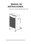
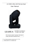
opticalCON I powerMONITOR
User Manual
version 1.4
opticalCON powerMONITOR
1. Warning & Important Notice
FCC Approval
This device complies with part 15 of the FCC Rules. Operation is subject
to the following two conditions: (1) This device may not cause harmful
interference, and (2) this device must accept any interference received,
including interference that may cause undesired operation.
CE Approval
Neutrik AG declares under its sole responsibility that the product opticalCON powerMONITOR to which this declaration is referred to has been
designed and manufactured in accordance with the following international
standards
IEC 61300; IEC 61326; IEC 60068-2-6; IEC 60068-2-31
CAUTION: Important Notice
The user manual or instruction manual for an intentional or unintentional
radiator shall caution the user that changes or modifications not expressly
approved by the party responsible for compliance could void the user's
authority to operate the equipment.
CAUTION: Battery
Avoid short circuits
Operate and charge the battery between 0°C and +45°C.
Do not heat the battery above 60°C.
Do not dispose of the battery by burning.
Do not solder directly to the battery.
Do not disassemble the battery.
Do not insert the battery in reverse polarity.
The Li-Io battery has a potential for fire or burning.
CAUTION: Dispose
Dispose of your instrument in accordance with the valid legal environmentally regulations in your country
WARNING: Laser Handling Precautions
Laser light can damage your eyes. Laser light is invisible. Viewing it
directly does not cause pain. The iris of the eye will not close involuntarily
when viewing a bright light, consequently, serious damage to the retina of
the eye is possible. Never look into the end of a fiber which may have a
laser coupled to it. DO NOT use magnifiers in the presence of laser
radiation. Diffused laser light can cause eye damage if focused with
optical instruments. Should accidental exposure to laser light be suspected, arrange for an eye examination immediately.
CAUTION: Cable Handling
Fiber optic cable is sensitive to excessive pulling, bending and crushing
forces. Consult the cable specification sheet for the cable you are installing.
Do not bend cable more sharply than the minimum recommended bend
radius. Do not apply more pulling force to the cable than specified. Do not
crush the cable or allow it to kink. Doing so may cause damage that can
alter the transmission characteristics of the cable which may have to be
replaced as a result.
2
opticalCON powerMONITOR
Content
1. Warning & Important Notice ...................................................................................................................... 2
2. Specifications............................................................................................................................................. 4
3. Keys and Connectors ................................................................................................................................ 5
4. Software Main Menu .................................................................................................................................. 7
5. Channel Reset / Threshold Selection ........................................................................................................ 8
5.1 Change Channel Designation.................................................................................................................. 9
6 Mode - Wavelength Selection (Single-mode) ........................................................................................... 10
6.1 Mode - Wavelength Selection (Multimode) ........................................................................................... 11
7 Battery Status / Instant Charging.............................................................................................................. 12
8 Power Control Selection ........................................................................................................................... 13
9 Appendix - Application .............................................................................................................................. 14
3
opticalCON powerMONITOR
2. Specifications
Power supply:
Battery (rechargeable):
Battery lifetime:
max. Current
Power Adapter:
Temp. range:
Housing:
Connectivity:
5V DC external
2x 1.5V AA
72 h
250 mA
110 VAC – 220VAC
0°C – 70°C
steel, gal/black painted
opticalCON; LC
Return loss:
Insert loss:
> 45 dB
< 0.5 dB
Factory calibration:
-5 dBm (+/- 0.1)
-12 dBm (+/- 0.3)
-24 dBm (+/- 0.5)
Area of operation:
Wavelengths:
SM: +3 dBm to -30 dBm
single-mode: 1310/1550 nm
multimode: 850/1300 nm
single-mode: 9/125 um
multimode: 50/125 um
Internal fiber:
Protection class:
Vibration:
Shock:
Signal smoothing:
FCC:
IP 40
IEC 60068
IEC 60068
1s
FCC / 47CFR Port 5 (Subpast B, Class B, digital Device)
4
opticalCON powerMONITOR
3. Keys and Connectors
No
1
2
3
4
5
6
7
8
9
10
11
12
13
Function
Power ON / OFF button
UP botton ▲
Down button ▼
INFO / SET button
Relative attenuation
Absolute attenuation
Charging character
Chosen channel
Threshold level
Fiber input - opticalCON
Fiber output - opticalCON
External power supply - (5V DC)
Alarm (red light)
5
opticalCON powerMONITOR
... Keys And Connectors
No
10
11
12
11 opticalCON NKO2*/LC
Function
Fiber input - opticalCON
Fiber output - opticalCON or LC
Power supply +5V DC
To change the batteries, occur following steps:
- remove safety cable tie
- open cover
- remove battery holder screws
- replace batteries
- close cover and secure with safety cable ties
Before use the powerMONITOR remove safety battery
strap.
6
opticalCON powerMONITOR
4. Software Main Menu
Attention: WDM modus at the
Wavelength section is only on
single-mode available
If the powerMONITOR turns on,
an internal test starts and checks
the proper functionality of the
alarm and LED.
7
opticalCON powerMONITOR
5. Channel Reset / Threshold Selection
1. Select "Channel Menu" using
or
.
2. To enter "Ch1 menu" push
twice.
This will reset the relative attenuation.
3. Select the current threshold level (dB) by
pushing
or
and finally
to save.
4. The secondary line indicates the chosen
threshold and the relative attenuation
(∆dB)
Pls. note: To switch OFF the alarm push
3 times.
8
opticalCON powerMONITOR
5.1 Change Channel Designation
1. Select "Channel Menu" using
or
.
2. To enter "Ch1 info" - menu press
twice.
3. To change the channel designation press
or
till display indicates "Ch1 info" - menu
and confirm with
.
4. Change the displayed symbol by using
or
and select character with
.
5. Repeat step 3 and 4 for additional characters.
6. To save move the curser to the right
end of the display.
7. Check the entry by pushing
.
(returns to main info after 10 seconds)
9
opticalCON powerMONITOR
6 Mode - Wavelength Selection (Single-mode)
Set the wavelength depending to your application: 1310 / 1550 nm or WDM for single-mode
1. Select the "Wavelength Menu"
using
2. Push
or
.
twice to modify the settings.
3. Hit
or
to switch between the
wavelengths and WDM section.
SM: 1310 / 1550 nm / WDM
MM: 850 / 1300 nm
4. Push
to save the settings. Now the
powerMONITOR restarts.
WDM section works only in single-mode
Pls. note: A modification of the wavelength
selection will reset all settings to factory
default.
10
opticalCON powerMONITOR
6.1 Mode - Wavelength Selection (Multimode)
Set the settings according your used wavelength and type of light source (LED, VCSEL)
1. Select the "Wavelength Menu"
using
2. Push
or
.
twice to modify the settings.
3. Hit
or
to switch between following wavelengths and type
of light source.
Symbol
MM850 LED
MM850 VCSEL
SM1300 LED
SM 1300 VCSEL
Description
850 nm, multimode, LED light source
850 nm, multimode, VCSEL light source
1300 nm, multimode, LED light source
1300 nm, multimode, VCSEL light source
4. Push
to save the settings. Now the powerMONITOR
restarts.
11
opticalCON powerMONITOR
7 Battery Status / Instant Charging
1. Select "Battery Menu" using
2. Press
or
.
.
3. Press
or
to switch between the
two charging modes.
4. To set a mode press
Mode
Dis - Charge \ &
Charge anyway τ
.
Function
Discharges battery before recharging (gently)
Starts battery charging immediately
Attention: To charge batteries connect the external power supply (NOPS-1RU-PM)!
12
opticalCON powerMONITOR
8 Power Control Selection
1. Press
or
till the "power control" menu is displayed.
If there is an external power supply
plugged in, the first line of the display
indicates EXTERNAL.
The second line shows the current
battery mode.
2. Hit
.
3. To switch between the battery mode
press
Mode
ACCU Auto \ & τ
ACCU Manual τ
NOT recharge! ¢
or
and confirm with
Function
Depending on the battery status the powerMONITOR starts to discharge/charge automatically (gently). Only works with rechargeable
batteries.
Without checking the battery status, it starts
immedidately to charge.
No charging.
Attention: The battery can only be charged by using an external power supply! (NOPS-1RU-PM)
13
opticalCON powerMONITOR
9 Appendix - Application
a) System monitoring with known output power
powerMONITOR
e.g. NO4SBB1-4PM
equipment
fiber output
power: - 5dBm
The powerMONITOR measures the deviation of the signal power at the end of the system as reference to the typical
fiber output power from the light source (e.g. DVI converter, SFP transceiver, etc.) according the device specifications.
At the example on top the powerMONITOR exhibits -6 dBm which means 1 dB attenuation in reference to the output power of -5
dBm.
Fiber output power
- Current power (absolute value):
I -5 dBm I
I -6 dBm I
System Attenuation (relative value ∆dB ): 1 dB
The following matrix exhibits the attenuation accuracy tolerances of absolute and relative values from the powerMONITOR.
Fiber Type
Single-mode
Multimode VCSEL
Multimode LED
Absolute Value [dBm]
0.5
1.0
1.0
Relative Value [∆dB]
0.1
0.5
0.5
14
opticalCON powerMONITOR
... Appendix - Application
b) System monitoring with unknown output power
powerMONITOR
e.g. NO4SBB1-4PM
CAS-FOMD
To determine the attenuation of a system, connect a light source
as e.g. Neutriks measurement KIT (CAS-FOMD1) with help of a LC
patchcable and the used opticalCON cable (e.g. NKO4S-R-0-501)
and powerMONITOR
(e.g. NO4SBB1-4PM).
The light source offers a typical output power of -3 dBm (2kHz
mode). The difference of the output power (∆dB) is the total attenuation of the system (cable + devices).
The difference between the recent power budget and the system
attenuation shows the corresponding threshold level.
After connect the device (transceiver, DVI-converter, etc.) with the
powerMONITOR.
light source
(unknown
output power)
Fiber Type
single-mode
multimode
Attenuation Range
-9 dB
-7 dB
Example:
Attenuation Range:
System Attenuation:
Set the threshold from the powerMONITOR according the calculated value (see example below).
If no power budget is known use typical attenuation values from
the table on the left.
1
...not included
I -9 dB I
I -5 dB I
Threshold Level: 4 dB
15
opticalCON powerMONITOR
Liechtenstein (Headquarters)
NEUTRIK AG, Im alten Riet 143, 9494 Schaan
T +423 237 24 24, F +423 232 53 93
[email protected]
Japan
Neutrik Limited, Yusen-Higashinihonbashi-Ekimae Bldg.,3-7-19
Higashinihonbashi, Chuo-ku, Tokyo 103
T +81 3 3663 47 33, [email protected]
Germany/Netherlands/Denmark/Austria
Neutrik Vertriebs GmbH, Felix-Wankel-Strasse 1
85221 Dachau, T +49 8131 28 08 90,
[email protected]
Hong Kong
Neutrik Hong Kong LTD., Workshop 14, 16 Floor,
Wah Wai Centre Nr. 38-40 Au Pui Wan Street, Shatin,
T +852 2687 6055, [email protected]
Great Britain
Neutrik (UK) Ltd., Westridge Business Park, Cothey Way
Ryde, Isle of Wight PO33 1 QT
T +44 1983 811 441
[email protected]
China
Ningbo Neutrik Electronics Co., Ltd., Shiqi Street, Yinxian Road West
Fengjia Villiage, Yinzhou Area, Ningbo, Zhejiang; 315153
T +86 574 88250488 800, [email protected]
France
Neutrik France SARL, Rue du Parchamp 13, 92100
Boulogne-Billancourt
T +33 1 41 31 67 50
[email protected]
USA
Neutrik USA Inc., 4115 Taggart Creek Road
Charlotte, North Carolina, 28208 USA
T 704- 972-3050
[email protected]
BDA 278
16