1
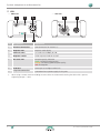
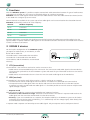
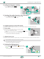
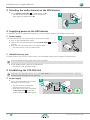
User Manual Contents A About this document 3 Designations3 Symbols on the device and packaging 3 Symbols in the documentation 4 Safety instructions 4 B System components and accessories 6 Controls 7 XTX7 XRX8 C Functions 9 Starting the linking process Supplying power to the repeater Supplying power to the XRX receivers Completing the linking process 19 19 19 19 Dual channel or stereo transmission with repeater 20 Mounting the antennas 20 Setting the Repeater switches 20 Selecting the audio channels 21 Supplying power to the XTX master 21 Starting the linking process 22 Supplying power to the repeater 22 Supplying power to the XTX slave and XRX receivers22 Completing the linking process 22 F Control options 23 Mute/Link button on the XTX device 23 Muting the audio signals 23 Linking process 23 10 Displaying the audio signal level 23 Mounting the antennas 10 Displaying the RF channel 24 Setting the Repeater switches 11 Selecting the RF channel 24 Selecting the audio channel on the XTX device 11 G Antenna Guide 25 Supplying power to the XTX master Power supply XIRIUM X battery pack 11 11 11 Radiation pattern 25 Diversity technology 25 Starting the linking process 11 Antenna selection 26 Selecting the audio channel on the XRX devices 12 Recommended antenna/cable combinations 26 Supplying power to the XRX devices Power supply XIRIUM X battery pack 12 12 12 Alignment27 Establishing the XTX-XRX link Power supply 12 12 Completing the linking process 13 Connecting the audio sources 13 Connecting audio sinks 14 E Configuration examples 15 XIRIUM X devices XTX (transmitter) XRX (receiver) D Installation of a single radio link 9 9 9 Multiple mono or stereo transmission 15 Mounting the antennas 15 Setting the Repeater switches 15 Selecting the audio channels 16 Supplying power to the XTX master 16 Starting the linking process 16 Supplying power to the XTX slaves and XRX receivers17 Completing the linking process 17 Mono transmission with repeater Mounting the antennas Setting the Repeater switches Selecting the audio channels Supplying power to the XTX master 2 17 18 18 18 19 Propagation of electromagnetic waves 28 Neutrik antenna range Omnidirectional antennas Directional antennas 28 28 28 H After operation 29 Discontinuing operation and disassembly 29 Transport29 Storage29 Care and cleaning 29 Servicing and repair 29 Disposal29 I Operation from the computer 30 Installing the XIRIUM X Companion 30 System requirements 30 Download30 Installing the software 30 Using the XIRIUM X Companion Starting the program Software structure 31 31 31 User Manual | 2014/09 BDA 420E About this document Menu bar Firmware update Closing the program Deinstalling the software J Service 32 32 33 33 33 Contact33 Troubleshooting33 Conformity declaration K Technical data 33 34 AAbout this document This document describes safe use of the XIRIUM X multichannel wireless network (referred to below as the XIRIUM X system). The XIRIUM X system comprises the XIRIUM X devices (XTX and XRX), antennas, power supplies and other accessories such as the XIRIUM X battery packs and connection cables. Designations Designation Note XIRIUM X system All components: XIRIUM X devices, cables, connectors, XIRIUM X battery packs XIRIUM X devices XTX devices, XRX devices Peripheral device All devices that can be connected to the XIRIUM X devices: Audio sources (transmitters) and audio sinks (receivers) Audio source All devices that transmit audio signals, e.g. instruments, microphones, tablets, MP3 devices, audio systems (amplifiers, mixers etc.) Audio sink All devices that receive audio signals, e.g. speakers, audio systems (amplifiers, mixers etc.) Symbols on the device and packaging Symbol Explanation CE conformity mark. The product was manufactured in compliance with applicable standards. Do not dispose of devices in domestic waste. Warning symbol. Read the instructions. User Manual | 2014/09 BDA 420E 3 About this document Symbols in the documentation Symbol Explanation ;; Pre-requisite: These conditions must be met before the following instructions are executed. XX Instruction: This requires action on your part. yy Result: Result of an executed instruction. Notes and tips for safe use of the devices and accessories: Observe these notes. Warning symbol: Highlights dangerous situations. Non-observance can result in personal injury. CAUTION! Warning: Highlights dangerous situations. Non-observance can result in damage to equipment. Safety instructions XX Carefully read the information contained in the User Manual for safe use of the XIRIUM X system and all accessories. XX Always keep this User Manual near the XIRIUM X devices for easy reference. XX Read and comply with the instructions of use for the connected peripheral devices. —— Intended use XX Only use the XIRIUM X devices in accordance with the description in this User Manual. XX Never use any accessories that are not expressly designed for the XIRIUM X devices. The XIRIUM X devices are not designed for outdoor use. XX Only use the XIRIUM X devices indoors. XX Protect the XIRIUM X devices against knocks and prevent them falling from shelves, tables or other items of furniture. XX Never open the housing of the XIRIUM X devices or replace any parts yourself. Unauthorised opening or repair can result in serious damage to the devices and injury to the operator. XX Only have the XIRIUM X devices repaired by an authorised dealer. —— Power packs XX Only use the special XIRIUM X battery packs for powering the XIRIUM X devices. Ensure that the XIRIUM X battery packs are undamaged and fully charged. XX Only use power packs with the same technical ratings for powering the XIRIUM X devices. Never use power packs with different charge levels. —— Electrical connection Risk of electric shock! XX Only connect the XIRIUM X devices to correctly installed power sockets. XX Do not touch the XIRIUM X devices or the connections with moist or wet hands. XX Ensure that the mains voltage and frequency of the XIRIUM X devices corresponds with the ratings of the supply network. XX Only use the supplied power supplies for connection to a power socket. Never make any modifications to the power supply. XX Before switching on the XIRIUM X devices always ensure that the power supply or the XIRIUM X battery pack shows no visible signs of damage, dents or kinks, flaws or cracks. Only use an undamaged power supply for connection to the power circuit. XX If the XIRIUM X devices are not used for a prolonged period of time, switch all the devices off and remove the mains connector from the socket. XX In the event of thunderstorms or the risk of voltage fluctuations in the power network: Switch the XIRIUM X devices off and remove the mains connector from the power socket. Damage to equipment caused by unsuitable operating and ambient conditions! XX Protect the XIRIUM X devices against dirt, dust, liquids, moisture, heat and full exposure to sunlight. XX Ensure that there is sufficient space between the XIRIUM X devices and other objects, especially those that become very warm themselves. To prevent overheating, never cover the devices. Risk of injury and damage to equipment caused by incorrect repairs! The XIRIUM X devices do not contain any parts that you can repair yourself. 4 User Manual | 2014/09 BDA 420E About this document XX Ensure that the mains cables are not kinked during operation, do not hang over sharp edges or come in contact with warm or hot surfaces. XX Never use the XIRIUM X devices if damage or faults occur on the power supply, the individual devices, indicators, controls or accessories. —— Please observe the following during operation: XX Ensure that the ambient conditions specified for the XIRIUM X devices in the technical data are complied with during operation. XX Never use the XIRIUM X devices if they do not work correctly, have been dropped or damaged, become wet or if parts have been immersed in water. XX Switch the XIRIUM X devices off immediately and disconnect them from the power supply if faults occur during operation. XX Do not use the XIRIUM X devices in rooms in which flammable or explosive substances, gases or vapours are present or can occur. User Manual | 2014/09 BDA 420E 5 System components and accessories BSystem components and accessories 1 2 3 4 6 7 8 9 5 Item XIRIUM X / Accessories 1 XTX (transmitter) NXX1TX-T 2 XRX (receiver) NXX1RX-T Accessories 10 11 13 12 3 Rod antenna NXA-3-360 4 Directional antenna NXA* 5 Omnidirectional antenna NXA-10-360-10 6 Installation adapter for the directional antenna NXA-SMA-MM 7 Antenna cable NKXA* 8 Data cable NKX-DATA 9 5-V power supply with Tiny-XLR connector NPS-10W-T 10 XIRIUM X battery pack NXBP-T-6 11 Manfrotto™ universal mounting clamp NXUC-M-15 12 Flight Case XIRIUM X – Basic Setup CAS-NXX-BASIC 13 Quick Start Guide * For the recommended antenna cable combination please refer to the section “G Antenna Guide” on page 26. 6 User Manual | 2014/09 BDA 420E System components and accessories Controls XTX —— XTX front 1 —— XTX rear 2 3 4 5 10 11 OFF 4 ON +48V metering press 4 s MUTE LINK 3 2 press GAIN GAIN 9 8 2s M OFF ON REPEATER 7 6 Item Designation Explanation 1 Antenna connection SMA connectors for antennas *) 2 Impedance switch Switch between phantom power / Hi-Z or line level. 3 Mute LED Mute indicator yy red: The device/audio channel is muted. yy green: The impedance switch is set to ON, a 1/4” TS connector is inserted. The device is ready for a Hi-Z instrument signal (e.g. direct connection of a guitar). yy flashes in green: The impedance switch is set to ON, the condenser microphone (48 V) can be supplied with phantom power. 4 Mute/Link button 5 Channel select Set audio channel M, 2, 3 or 4. 6 Repeater switch Switch repeater mode on and off 7 Status LED Indicator for: yy RF ON yy Linking process yy Input signal (dBFS) yy RF channel yy Changing the RF channel 8 Gain-up Increase the volume. 9 Gain-down Lower the volume. 10 Combo socket Connection socket for analogue audio sources with XLR connector, 1/4” TRS connector or 1/4” TS connector 11 Tiny-XLR connection Connection for 5V power supply via the Tiny-XLR connector yy Switch the audio channel to mute. yy Start and finish the linking process. yy Indication functions *) When using a remote antenna including antenna cables we recommend securing the cable with a spanner (tightening torque = 1 Nm). User Manual | 2014/09 BDA 420E 7 System components and accessories XRX —— XRX front —— XRX rear 1 2 3 6 7 REPEATER 4 3 2 M OFF ON REPEATER 5 Item Designation Explanation 1 Antenna connection SMA connectors for antennas *) 2 Repeater LED Repeater mode display 3 Channel select Set audio channel M, 2, 3 or 4. 4 Repeater switch Switch repeater mode on and off 5 RF status LED Reception quality indication green: Reliable reception quality orange: Unreliable, good reception quality red: No reception 6 XLR-OUT XLR output to analogue audio sinks 7 Tiny-XLR connection Connection for 5V power supply via Tiny-XLR *) 8 4 When using a remote antenna including antenna cables we recommend securing the cable with a spanner (tightening torque = 1 Nm). User Manual | 2014/09 BDA 420E Functions CFunctions With the XIRIUM X system it is possible to replace conventional cable connections between all types of audio sources and audio sinks (referred to in this manual as peripheral devices) by a wireless connection. XIRIUM X transmits audio signals without losses on four audio channels within one radio channel (RF channel) on the 5-GHz band with a range of up to 500 metres. Four RF channels are available in the system. Up to four audio signals can be transmitted on the selected RF channel. XIRIUM X automatically searches for a free frequency. Channel Medium frequency Ch 36 5180 MHz Ch 40 5200 MHz Ch 44 5220 MHz Ch 48 5240 MHz Different applications are possible with the direct transmission between the audio source and the audio sink or the repeater mode. In repeater mode the audio signals can also overcome obstacles and also be transmitted to the receivers if there is no direct visual contact. XIRIUM X devices For the simplest configuration of the XIRIUM X system you require an audio source, an XTX device, an XRX device and an audio sink. The audio source is connected to the XTX device. The audio sink is connected to the XRX device. The XTX device and the XRX device are connected wirelessly. XTX (transmitter) The XTX device is the transmitter and can be used as a master or slave. yy Audio sources are connected directly to the XTX master. The XTX master sends audio signals to the XRX devices. The XTX master synchronises the entire XIRIUM X system and sends the sync information to the XTX slave and all XRX devices. yy Audio sources are connected to the XTX slave. The XTX slave sends audio signals to the XRX devices. XRX (receiver) The XRX device is the receiver and is either used as a “simple” receiver or as a repeater. yy The XRX receiver receives audio signals from XTX devices. An audio sink is connected to the XRX receiver. yy The repeater receives audio signals from XTX devices and transmits them without losses to the XRX receivers. A repeater can receive and forward two audio signals. It is therefore possible to transmit stereo or multiple mono signals through a repeater. —— Repeater mode With the repeater mode the system can be extended by two important functions: yy Extension of the transmission range: Obstacles can be overcome. The receiver in repeater mode receives the audio signal from the transmitter and forwards it to the other receivers. yy Diversity: If you use an XRX device as a repeater, the reception reliability in the XIRIUM X system can be further enhanced. The XTX receiver works with diversity, i.e. it automatically uses the stronger signal, either directly from the XTX device or from the repeater. In repeater mode a repeater can forward up to two audio signals. Only one repeater can be used per RF channel. User Manual | 2014/09 BDA 420E 9 Installation of a single radio link DInstallation of a single radio link Installation of a single radio link between an XTX transmitter and any number of XRX receivers in broadcast mode. MASTER 4 3 2 4 3 2 M M This example shows the simplest, direct transmission path from an audio source to the audio sink through an audio channel. The XTX master sends the audio signal from the audio source to the XRX client that is connected to an audio sink. Several XRX devices can be used in broadcast mode. All XRX receivers receive the same audio signals from the XTX master. Broadcast mode enables you to connect any number of XRX receivers to one XTX device. These XRX devices all receive the same audio signal from the XTX device on one audio channel. —— For this installation you require: yy One XTX device yy Any number of XRX devices (for broadcast mode) yy One antenna for each XIRIUM X device yy One audio source with a suitable connection cable yy One audio sink per XRX device with a suitable connection cable yy Power supplies or XIRIUM X battery packs for the XIRIUM X devices XX Unpack all parts for this setup. Keep the original packaging for transport or storage purposes. XX Check the contents of the packaging for visible transport damage. XX Check whether the supplied items comply with the information on the delivery note. XX If the packaging or supplied parts are damaged: Do not start operation of the devices. Contact the vendor or the Neutrik customer service department. Mounting the antennas Antennas must be mounted on the XIRIUM X devices for wireless transmission. Select the correct antenna for your configuration. For more information on this topic, refer to the section “G Antenna Guide”. XX Mount the antennas onto the antenna connections 1 , 1 of the XIRIUM X devices. XX Align the antennas. 1 >2m XTX XRX 4 OFF ON 8V +4 ress 4s gp erin met IN GA AIN G 3 TE MU K LIN s es pr 2s 2 ON M OFF R E AT PE RE 4 3 2 M OFF RE PE 10 O AT N ER User Manual | 2014/09 BDA 420E Installation of a single radio link Setting the Repeater switches the Repeater switches 6 , 4 on the XTX device and on all XRX devices to OFF. XX Set 2 6 XTX 4 F OF ON ONF OF 8V 8V +4 +4 ing er met s4 es pr s TEE MU MUT K LINK LIN s pres 2s 3 2 XRX 4 3 2 M M OFF ON ON R 4 F RTE OF TE A EA PEREP 3 RE 2 IN N GGA AI M OFF IN GAN RE GAI PE OFF O AT N ER ON REPEATER Selecting the audio channel on the XTX device XX Set the Channel select dial 5 of the XTX yy The XTX device is then the XTX master. device to M. 3 XTX 4 F OF ON 8V +4 g erin s4 es pr s TE MU K LIN s es pr 2s met 3 2 ON M OFF R E AT PE RE IN GA IN GA 4 3 2 M Supplying power to the XTX master The XIRIUM X devices are supplied with power by means of a power supply or the XIRIUM X battery pack. Power supply If the XTX master is near a power socket, use the power supply. XX Only use the supplied power supply. XX Connect the Tiny-XLR connector to the Tiny-XLR socket master. XX Insert the mains connector into a mains power socket. yy The XTX master switches on automatically. 4 XTX 11 of the XTX XIRIUM X battery pack If the XIRIUM X devices are not near a power socket, use the XIRIUM X battery pack to power the XIRIUM X devices. To fit the XIRIUM X battery pack, refer to the instructions. XX Fit the yy The XIRIUM X battery pack on the XTX master. XTX master switches on automatically. Starting the linking process and hold the Mute/Link button 4 of the XTX master until the status 7 lights up briefly in orange and then flashes in green. yy The linking process on the XTX master is then initiated. XX Press 5 4 XTX F OF ON 8V +4 s4 es g pr s K LIN s es pr erin met TE MU 2s 3 2 ON M OFF R E AT PE RE IN GA IN GA User Manual | 2014/09 BDA 420E 11 Installation of a single radio link Selecting the audio channel on the XRX devices XX Set the Channel select dial 3 of all XRX devices to M. yy The XRX devices become XRX receivers and receive 7 audio signals on audio channel M. XRX 4 3 2 M OFF RE PE 4 O AT N ER 3 2 M Supplying power to the XRX devices The XIRIUM X devices are supplied with power by means of a power supply or the XIRIUM X battery pack. Power supply If the XRX receivers are near a power socket, use the power supply. XX Only use the supplied power supply. XX Connect the Tiny-XLR connector to the Tiny-XLR socket 7 of the XRX receivers. XX Insert the mains connector into a mains power socket. yy The XRX receivers switch on automatically 8 XRX XIRIUM X battery pack If the XRX receivers are not near a power socket, use the XIRIUM X battery pack to power the XRX receivers. To fit the XIRIUM X battery pack, refer to the instructions. XX Fit the yy The XIRIUM X battery pack on the XRX devices devices switch on automatically. Establishing the XTX-XRX link Ensure that the receiving antennas are at least two metres away from the transmitting antennas to prevent interference occurring due to close proximity. Power supply XX Ensure that the XRX devices are within the range of the XTX master. yy yy 12 The XRX receivers automatically connect to the XTX master. When the link has been established, the RF status LED 5 on the XRX receiver switches from red to green. 9 XTX XRX 4 OF F ON 8V +4 s4 es g pr erin met s 3 TE MU LIN K ss pre 2s 2 M ON R TE EA F OF REP 4 3 IN GA 2 IN GA >2m M OF F REP EA ON TE R User Manual | 2014/09 BDA 420E Installation of a single radio link Completing the linking process ;;All XRX receivers have connected to the XTX master. ;;All RF status LEDs 5 on the XRX receivers light up green. XX Briefly press the Mute/Link button 4 on the XTX master. yy The linking process is completed. yy The status LED 7 on the XTX master stops flashing in green and lights up permanently in green. 10 4 F OF XTX ON 8V +4 ing ter s4 es pr s E MUT LINK ss pre 2s me 3 2 M ON F OF ER AT PE RE IN GA IN GA Connecting the audio sources Audio sources such as dynamic microphones, condenser microphones, instruments (Hi-Z signal) and line level signals are connected to XTX devices. To prevent signal peaks we recommend activating the mute function on the XIRIUM X devices before connecting the peripheral devices. (Switch the devices to mute.) CAUTION! Incorrect connection ratings can result in damage to the device, the accessories and the connected audio source! XX Ensure that the input signal on the XTX device is set correctly (phantom power / HI-Z or line). —— Phantom power / HI-Z or line adjustment You can set the XTX master so that you can use the phantom power / HI-Z or line-in. Select the corresponding input signal for the respective devices (dynamic microphones and line signals or electric guitars and condenser microphones). XX Slide the impedance switch 2 to ON. yy The input for the audio source is used for phantom supply. yy You can now either connect a condenser microphone with the XLR connector or an instrument signal (Hi-Z) with a ¼” TS connector. XX Slide the impedance switch 2 to OFF. yy The input for the audio source is switched to line. yy With this input signal setting you can connect devices with line level (e.g. mixers) or dynamic microphones (XLR connectors or ¼” TS connectors). Dynamic microphone or line signal OFF XLR 1/4” TRS Condenser microphone ON +48V OFF XLR Instrument signal 1/4” TS ON +48V —— Connecting an audio source XX Connect a suitable audio cable to the audio source. XX Insert the connector of the audio cable into the combo User Manual | 2014/09 BDA 420E input socket 10 on the XTX device. 13 Installation of a single radio link Connecting audio sinks To prevent signal peaks we recommend activating the mute function on the XTX device before connecting the audio sinks. (Switch the devices to mute.) Caution! Risk of hearing damage! Risk of damage to the audio sink if the volume is set too high! XX Set the volume of the audio source to minimum before connecting to the XTX device. Audio sinks such as speakers, headphones, audio amplifiers and mixers are connected to the XRX devices. XX Connect a suitable audio cable to the audio sink. XX Insert the connector of the audio cable into the XLR-OUT socket 5 on the XRX device. The XIRIUM X system is now ready for use. 14 User Manual | 2014/09 BDA 420E Configuration examples EConfiguration examples Three typical applications and their configurations are described in detail below. First make sure you understand the functions of the XIRIUM X devices. To this purpose read the sections “C Functions” and “D Installation of a single radio link”. Multiple mono or stereo transmission Transmission of multiple mono or stereo audio signals on up to four audio channels within one RF channel. In the event of multi-channel transmission, all audio signals are transmitted synchronously. In broadcast mode any number of XRX receivers can receive the audio signal of an audio channel. MASTER 4 3 2 M ... 4 3 2 M SLAVE 4 3 2 M ... 4 3 2 M SLAVE 4 3 2 M ... 4 3 2 M SLAVE 4 3 2 M ... 4 3 2 M —— For this installation you require: Necessary devices and components yy At least two and at the most four XTX devices yy At least two XRX devices yy One antenna for each XIRIUM X device. yy One audio source for each XTX device with a suitable connection cable yy One audio sink for each XRX device with a suitable connection cable Mounting the antennas >2m XX Select the correct antennas for your configuration. XX Mount an antenna on each XIRIUM X device. XX Align the XIRIUM X devices and antennas. 4 OFF 3 ON TE ress LIN p ing OFF 2s R E AT PE RE s es pr ON M K 4s er met 2 MU 8V +4 4 3 IN GA 2 AIN M G OFF RE PE O AT N ER Setting the Repeater switches the Repeater switches and XRX devices to OFF. XX Set 6, 4 on all XTX 4 F OF ON ONF OF 8V 8V +4 +4 g erin s es pr 4s TEE MU MUT K LINK LIN s pres 2s met 3 2 4 3 2 M M OFF ON ON R 4 F RTE OF TE A EA PEREP 3 RE 2 IN N GGA AI M OFF IN GAN RE GAI PE OFF O AT N ER ON REPEATER User Manual | 2014/09 BDA 420E 15 Configuration examples Selecting the audio channels —— XTX master one XTX device set the Channel select dial to M. yy This XTX device has the master function. XX On Master 5 4 F 3 OF ON 8V +4 erin met s s4 es g pr TE 2 MU K LIN pr ON M OFF 2s R E AT PE RE s es IN GA IN GA 4 3 2 M —— XTX slave Slave the other XTX devices set the Channel select dial 5 to 2, 3 and 4. yy These XTX devices are then XTX slaves. yy If the Channel select dial is set to 2, this XTX slave transmits on audio channel 2. yy If the Channel select dial is set to 3, this XTX slave transmits on audio channel 3. yy If the Channel select dial is set to 4, this XTX slave transmits on audio channel 4. Slave XX On Slave 4 F OF ON 8V +4 ing s s4 es pr F 3 2 LINK OF ON M ON F OF ss 2s 8V +4 ER AT PE RE pre ter me E MUT 4 ing LINK ss pre 2s ter me N E MUT s s4 es pr 4 F 3 2 OF ON M ON F OF 8V +4 ER AT PE RE me ing GAI 2 ss 2s M F OF ON ER AT PE RE GAI N N GAI GAI 4 4 4 3 3 3 2 2 M 3 LINK N GAI N E MUT pre ter N GAI s s4 es pr 2 M M —— XRX receivers XX On the XRX receivers set the Channel select dial 3 to M, 2, 3 or 4, depending from which XTX device the XRX receiver should receive the audio signal. yy The XRX receivers receive audio signals on audio channel M, 2, 3 or 4. 4 3 2 M OFF RE PE 4 O AT N ER 3 2 M Supplying power to the XTX master XX Connect a power supply or a XIRIUM X battery pack to the XTX master. yy The XTX master switches on. Starting the linking process the Mute/Link button 4 on the XTX master for two seconds until the status LED 7 lights up briefly in orange. yy The status LED 7 flashes in green: The linking process is then initiated. XX Press 16 4 F OF ON 8V +4 s4 g erin pres s TE MU K LIN s es pr 2s met 3 2 ON M OFF R E AT PE RE IN GA IN GA User Manual | 2014/09 BDA 420E Configuration examples Supplying power to the XTX slaves and XRX receivers XX Connect the power supplies or XIRIUM X battery packs to the XTX slaves and the XRX receivers. yy The XTX slaves and XRX receivers switch on. The status LEDs 7 of the XTX slave and the RF status LEDs green when the link has been established. of the XRX receivers switch from red to 5 Completing the linking process XX Briefly press the Mute/Link button 4 . yy The status LED 7 switches from flashing yy 4 green F OF ON 8V +4 s4 and lights up permanently in green. The linking process is completed. ing es pr s E MUT LINK ss pre 2s ter me 3 2 M F OF ON ER AT PE RE IN GA IN GA The XIRIUM X system is now ready for use. Mono transmission with repeater To overcome obstacles or enhance the reception reliability with diversity, one XRX device is used in repeater mode. Extended true diversity MASTER OFF Extension of the transmission range / overcoming obstacles REPEATER ON OFF REPEATER ON REPEATER MASTER OFF ON REPEATER OFF REPEATER OFF ON REPEATER ON REPEATER —— For this installation you require: Necessary devices and components yy One XTX device as master yy One XRX device as repeater yy Any number of XRX devices as receivers yy One antenna for each XIRIUM X device. yy One audio source with a suitable connection cable yy One audio sink for each XRX device with a suitable connection cable User Manual | 2014/09 BDA 420E 17 Configuration examples Mounting the antennas >2m XX Select the correct antennas for your configuration. XX Mount an antenna on each XIRIUM X device. XX Align the XIRIUM X devices and antennas. 4 OFF 3 ON TE g erin ss pre 2 MU 8V +4 LIN OFF 2s met R E AT PE RE s es pr ON M K 4s 4 3 IN GA 2 IN GA M OFF RE PE O AT N ER Setting the Repeater switches the Repeater switches 6 , 4 on the XTX device and one XRX device to ON. yy The XTX device is then the master. yy This XRX device is then the repeater. XX Set 4 4 F OF ON ONF OF 8V 8V +4 +4 g erin s es pr 4s TEE MU MUT K LINK LIN s pres 3 2 3 2 OFF 2s met M M ON ON R 4 F RTE OF TE A EA PEREP 3 RE 2 IN N GGA AI M OFF IN GAN RE GAI PE OFF O AT N ER ON REPEATER the Repeater switches 4 on all other XRX devices to OFF. yy These XRX devices are then XRX receivers. XX Set 4 3 2 M OFF RE PE OFF O AT N ER ON REPEATER Only one repeater can be used for each RF channel. Selecting the audio channels If a repeater is used, the number of usable audio channels is limited to two. —— XTX master Master the Channel select dial 5 on the XTX device to M. yy This XTX device has the master function. XX Set 4 F OF ON 8V +4 es g pr erin met s4 s TE MU 3 2 K LIN ON M OFF 2s R E AT PE RE s es pr AIN G AIN G 4 3 2 M —— XRX receivers the Channel select dial 3 on the XRX receivers to M. yy The XRX receivers receive audio signals on audio channel M. XX Set 4 3 2 M OFF RE PE 4 O AT N ER 3 2 M 18 User Manual | 2014/09 BDA 420E Configuration examples Supplying power to the XTX master XX Connect a power supply or a XIRIUM X battery pack to the XTX master. yy The XTX master switches on. Starting the linking process the Mute/Link button 4 on the XTX master for two seconds until the status LED 7 lights up briefly in orange. yy The status LED 7 flashes in green: The linking process is then initiated. XX Press 4 F 3 OF ON 8V +4 es g pr erin met s s4 TE 2 MU K LIN es pr ON M OFF R E AT PE RE s 2s AIN G AIN G Supplying power to the repeater XX Connect a power supply or a XIRIUM X battery pack to the repeater. yy The repeater switches on. yy The repeater LED 2 flashes in green. yy The RF status LED 5 lights up in red. The RF status LED 5 on the repeater changes from red to green when the link has been established. Supplying power to the XRX receivers XX Connect a power supply or a XIRIUM X battery pack to the XRX receivers. yy The XRX receivers switch on. yy The RF status LEDs 5 light up in red. The RF status LED 5 on the XRX receivers change from red to green when the link has been established. Completing the linking process XX Briefly press the Mute/Link button 4 . yy The status LED 7 switches from flashing yy and lights up permanently in green. The linking process is completed. 4 green F OF ON 8V +4 ing s4 es pr s E MUT LINK ss pre 2s ter me 3 2 M F OF ON ER AT PE RE IN GA IN GA The XIRIUM X system is now ready for use. User Manual | 2014/09 BDA 420E 19 Configuration examples Dual channel or stereo transmission with repeater MASTER 4 3 2 4 3 2 M OFF ON ... M REPEATER REPEATER OFF OFF ON OFF ON REPEATER ON REPEATER SLAVE 4 3 2 4 3 2 M OFF ON REPEATER ... To overcome obstacles or enhance the reception reliability with diversity, one XRX device is used in repeater mode. If a second XTX device is used as a slave, it is also possible to transmit stereo or two mono signals through the repeater. The XTX master sends the audio signal on audio channel M. The XTX slave sends an audio signal on audio channel 2. The repeater receives both audio signals and sends them separately to the XRX receivers. M REPEATER —— For this installation you require: Necessary devices and components yy One XTX device as master yy One XTX device as slave yy One XRX device as repeater yy Any number of XRX devices as receivers yy One antenna for each XIRIUM X device. yy Two audio sources with a suitable connection cable yy One audio sink for each XRX device with a suitable connection cable Mounting the antennas >2m XX Select the correct antennas for your configuration. XX Mount an antenna on each XIRIUM X device. XX Align the XIRIUM X devices and antennas. 4 OFF 3 ON TE g ss pre in eter 2 MU 8V +4 LIN OFF 2s R E AT PE RE s pres m ON M K 4s 4 3 IN GA 2 IN GA M OFF RE PE O AT N ER Setting the Repeater switches the Repeater switches 6 , 4 on the XTX device and on an XRX device to ON. yy The XTX device is then the master. yy This XRX device is then the repeater. XX Slide 4 4 F OF ON ONF OF 8V 8V +4 +4 es g pr in eter s s4 TEE MU MUT K LINK LIN s pres 3 2 3 2 OFF 2s m M M ON ON R 4 F RTE OF TE A EA PEREP 3 RE 2 IN N GGA AI M OFF IN GAN RE GAI PE OFF O AT N ER ON REPEATER the Repeater switches 4 on all other XRX devices to OFF. yy These XRX devices are then XRX receivers. XX Set 4 3 2 M OFF RE PE OFF O AT N ER ON REPEATER 20 User Manual | 2014/09 BDA 420E Configuration examples the Repeater switch 6 on the second XTX device to OFF. yy This XRX device is then the XTX slave. XX Slide 4 F 3 OF ON TEE MU MUT K LINK LIN ONF OF 8V 8V +4 +4 g pr erin met s4 es s 2 4 3 2 M ON ON R M OFF F RTE OF TE A EA PEREP RE s pres 2s IN N GA AI G IN GAN GAI OFF ON REPEATER Selecting the audio channels If a repeater is used, the number of usable audio channels is limited to two. —— XTX master Master one XTX device set the Channel select dial to M. yy This XTX device has the master function. XX On 5 4 F OF ON 8V +4 LIN es g pr erin met TE MU 3 2 K s s4 ON M R E AT OFF PE RE s es pr 2s IN GA IN GA 4 3 2 M —— XTX slave XX On the XTX slave set the Channel select dial Slave 5 to 2. yy 4 F OF The XTX slave sends audio signals on audio channel 2. ON 8V +4 erin met s4 g pr es s TE MU K LIN pr es s 2s 3 2 ON M OFF R E AT PE RE IN GA IN GA 4 3 2 M —— XRX receivers XX On the XRX receivers that should receive audio signals from the XTX master set the Channel select dial 3 to M. yy The XRX receivers receive audio signals on audio channel M. XX On the XRX receivers that should receive audio signals from the XTX slave, set the Channel select dial 3 to 2. yy The XRX receivers receive audio signals on audio channel 2. 4 4 3 3 2 2 4 3 M 2 4 3 M M OF F RE PE ON ATE R 2 M OF F RE PE ON ATE R Supplying power to the XTX master XX Connect a power supply or a XIRIUM X battery pack to the XTX master. yy The XTX master switches on. User Manual | 2014/09 BDA 420E 21 Configuration examples Starting the linking process the Mute/Link button 4 on the XTX master for two seconds until the status LED 7 lights up briefly in orange. yy The status LED 7 flashes in green: The linking process is then initiated. XX Press 4 F 3 OF ON 8V +4 s s4 es er met pr ing TE 2 MU K LIN es pr ON M OFF 2s R E AT PE RE s IN GA IN GA Supplying power to the repeater XX Connect a power supply or a XIRIUM X battery pack to the repeater. yy The repeater switches on. yy The repeater LED 2 flashes in green. The RF status LED 5 on the repeater changes from red to green when the link has been established. Supplying power to the XTX slave and XRX receivers XX Connect the power supplies or XIRIUM X battery packs to the XTX slave and the XRX receivers. yy The XTX slave and XRX receivers switch on. The status LED 7 on the XTX slave and the RF status LEDs green when a link has been established. of the XRX receivers switch from red to 5 Completing the linking process XX Briefly press the Mute/Link button 4 . yy The status LED 7 switches from flashing yy and lights up permanently in green. The linking process is completed. 4 green F OF ON 8V +4 s4 ing es pr s E MUT LINK ss pre 2s ter me 3 2 M F OF ON ER AT PE RE IN GA IN GA The XIRIUM X system is now ready for use. 22 User Manual | 2014/09 BDA 420E Control options F Control options Mute/Link button on the XTX device The Mute/Link button 4 Mute/Link button 4 can be used to make various settings or display settings. Function Press briefly. Mute / unmute the device Press for two seconds until the status LED in orange. 7 lights up briefly Start the linking process Press for four seconds until the status LED in red. 7 lights up briefly Displaying the audio signal level Press for six seconds until the status LED in green. lights up briefly 7 Press for eight seconds until the green light goes out. RF channel indication Change the RF channel Muting the audio signals Every audio channel between an XTX and an XRX device can be individually muted. XX Briefly press the Mute/Link button 4 on the XTX device. yy The XTX device is then muted. yy All XRX devices that are in broadcast mode are also muted. XX Briefly press the Mute/Link button 4 again. yy The mute function of the XTX device and all XRX devices that are in broadcast mode is cancelled. Linking process —— Starting XX Press the Mute/Link button 4 for two seconds. yy The status LED 7 lights up in orange. XX Release the Mute/Link button 4 . yy The status LED 7 flashes in green. —— Finish ;;The links to the XRX devices were established. ;;The RF status LED 5 on the XRX devices lights up green. XX Briefly press the Mute/Link button 4 . yy The linking process is completed. The linking process is finished automatically after 10 minutes if it is not finished with the Mute/Link button 4 . Displaying the audio signal level You can have the volume level of the device indicated. XX Press the Mute/Link button 4 for four seconds until the status LED 7 lights up in red. yy The status LED 7 shows the volume level. Status LED Audio signal level — < 40dBFS green ≥ 40 dBFS orange ≥ 18 dBFS red ≥ 3 dBFS The level indication remains active for 10 minutes before it is automatically cancelled. To cancel the volume indication manually, briefly press the Mute/Link button 4 . User Manual | 2014/09 BDA 420E 23 Control options Displaying the RF channel You can also have the RF channel currently in use indicated by the status LED 7 . XX Hold down the Mute/Link button 4 for four seconds until the status LED 7 lights up in green. yy The status LED 7 shows which RF channel is in use. Status LED RF channel Flashes once in red 36 Flashes twice in red 40 Flashes three times in red 44 Flashes four times in red 48 Selecting the RF channel The XTX devices are set to RF channel 36 when they leave the works. The RF channel can be changed manually. XX Press the Mute/Link button 4 until the green status LED 7 goes out. yy The XTX device switches from the currently set RF channel to the next higher channel. The selected RF channel remains programmed, even if the XTX device is switched off. 24 User Manual | 2014/09 BDA 420E Antenna Guide GAntenna Guide This guide is provided as a brief overview of the antennas, their directionality and installation versions so that you can use these according to your requirements and use alternative options in the event of drop outs. Stable wireless transmission starts with the selection of the right antennas for the respective setup. The supplied rod antennas cover a range of 360° (on the transmission and reception ends). The wavelengths in the 5-GHz range are very short but very suitable for transmission, as they are easily reflected by walls. Radiation pattern Every antenna has a specific radiation pattern. This pattern, also referred to as the directional radio pattern, determines the orientation of the antenna. The directional radio pattern is normally shown in polar coordinates as a polar diagram. There are omnidirectional antennas and directional antennas. While an omnidirectional antenna radiates over a range of 360° (as the name suggests), a directional antenna has a specific preferred direction. The “dBi”, the so-called gain of an antenna, indicates how many times stronger the signal in this preferred direction is than with a comparable antenna (isotropic antenna). Section “Neutrik antenna range” on page 28 contains an overview of our range of antennas. Diversity technology When electromagnetic waves are radiated, the same problem occurs as with sound waves. The signal does not only reach the receiver on a direct path, but also by means of reflections from the wall, floor etc. In contrast to the direct signal, phasing of the reflected signals is shifted. As a result, overlapping signals cancel one another at various points in the room. For this reason two antennas are often used on the receiving end. If one antenna is in a dead zone, the signal of the second antenna can be used. This increases the transmission reliability considerably. MASTER OFF REPEATER ON OFF REPEATER ON REPEATER OFF ON REPEATER As two transmission and receiver units are used when a repeater is employed, this can be regarded as an extended true diversity – “extended” as the repeater can be placed in an optimised position. The diversity technology can, however, also be implemented on the transmitter end. On the XIRIUM X system the additional use of a repeater ensures such a diversity setup and is aimed at keeping the radio transmission stable. The master transmits to both the repeater and the receiver. The repeater receives this signal and forwards it to the receiver so that two signals arrive at the receiver, and the strongest signal is used. To this purpose we recommend keeping the path between the XTX master and the repeater free from obstacles. Make sure the repeater is in a secure position. User Manual | 2014/09 BDA 420E 25 Antenna Guide Antenna selection In rooms with a wide range of reflection options we recommend using the supplied NXA-3-360 rod antennas (omnidirectional antennas). If you have placed the XRX at a place where signals are cancelled, it is often sufficient to move the device a few centimetres to reach a reliable zone. Alternatively, an additional repeater can be positioned in such cases that enables a diversity setup and thereby increases the transmission reliability. To increase the range and also the stability, we recommend using directional antennas on the receivers (NXX1RX-T). The opening angle (horizontal) of our directional antennas ranges from 40° to 60°. The RF signal is received more strongly inside this opening angle and the range is increased, and interference signals outside this angle are reduced at the same time. REPEATER NXA-3-360 In the event of longer distances, we recommend switching to directional antennas and establishing a point-to-point link. The directional antenna can be either screwed on with a suitable antenna cable or also directly on the receiver with an SMA adapter. The latter setup strengthens reception, as the signal remains unaffected by cable attenuation. 55° 35° vertikal 60° 40° horizontal NXA-10-60-55 NXA-14-40-35 NKXA-4,5 NKXA-4,5 On antennas with a higher gain than that of the supplied 2.3-dBi omnidirectional antennas that are mounted directly on the device: XX Only use antennas with the NXX1RX-T receiver if it is NOT in repeater mode. With the NXX1RX-T receiver (in repeater mode) and the NXX1TX-T transmitter (in all operating modes): XX Ensure that the correct antenna cable (refer to the table: “Recommended antenna/cable combinations” on page 26) is used between the device and the receiver. Only then can compliance with the permitted values of the directives be ensured. Recommended antenna/cable combinations Antenna type NXA-10-60-55 NXA-10-360-10 NXA-14-40-35 Cable type Cable length (m) NKXA - 4.5 4.5 • • − NKXA - 8 8 • • − NKXA - 12 12 − − • NKXA - 15 15 − − • NXA-SMA-MM Adapter •* − •* * Only with XRX (if repeater mode is switched off). 26 User Manual | 2014/09 BDA 420E Antenna Guide Alignment For reliable transmission in the 5-GHz range we recommend a parallel antenna configuration with a line of sight (LOS). The omnidirectional antenna NXA-10-360-10 is only omnidirectional in a horizontal direction. In a vertical direction it has a concentrated 10° beam. XX Position the omnidirectional antenna at the same height as the receiving antenna. 10° 10° 10° 10° If the antennas are positioned above the heads of the audience, you prevent absorption of the electromagnetic waves by their bodies. Remember that around 75 per cent of the human body is water and it therefore absorbs the waves very well. Antennas absorb the energy of an electromagnetic wave. If several receivers (antennas) are positioned too close to one another, both antennas receive less energy and the strength of the reception signal decreases. In addition there should not be any objects within a range of 15 cm around the antenna. This distance should be even greater around metal objects. User Manual | 2014/09 BDA 420E 27 Antenna Guide Propagation of electromagnetic waves The electromagnetic waves are susceptible to several forms of interference. These include the following: Reflections Electrically conductive surfaces act as a mirror for electromagnetic waves. The following applies: The angle of incidence is the same as the angle of reflection. Absorption In this case some of the electromagnetic waves are absorbed by the medium and converted into heat. Diffraction Diffraction occurs, for example, on grids, in gaps and on edges. If multiple diffractions occur on grids, interference occurs. -90 -90 -120 -150 180 -20 -10 -6 -3 Omnidirectional antennas —— NXA-3-360 / 5-GHz antenna with 2.3 dBi gain 150 120 Radiation pattern: -90 -60 -150 180 -20 -10 -6 -3 150 0 120 60 Horizontal: 360° 0 0 Antenna radiates in all directions (red circle). -60 -150 180 -10 -6 -3 0 150 0 -20 180 120 -3 0 -20 -10 -6 -3 0 0 60 -120 180 120 180 -20 -6 -120 -3 0 0 30 180 -20 -10 -6 -3 -150 -120 60 Vertical: 55° 90 0 0 180 -20 -60 -10 -6 -3 0 -30 -60 -90 -3 0 -6 60 -3 0 0 0 30 60 0 60 90 180 -20 30 -10 -6 -3 -150 -120 60 0 0 -30 -60 -90 90 Horizontal: 40° Vertical: 35° 90 60 150 0 0 30 120 -150 -120 -6 120 30 -20 -10 150 60 150 -60 -3 90 150 -30 -90 Horizontal: 60° 180 -10 120 -60 -150 -30 90 28 60 150 30 120 -20 120 150 120 -6 Radiation pattern: -90 120 -30 -10 -10 -30 120 60 90 -150 -90 -20 90 90 -60 -30 30 150 30 60 —— NXA-14-40-35 / 5-GHz antenna with 14 dBi gain Radiation pattern: -90 0 30 -150 90 150 0 -60 150 30 120 -120 180 -3 90 Vertical: 10° 0 -30 150 -6 -90 -150 Horizontal: 360° -6 -10 120 60 90 Directional antennas —— NXA-10-60-55 / 5-GHz antenna with 10 dBi gain 180 -20 150 30 -30 -10 -30 -120 Vertical: 360° -90 -120 -20 -60 -150 -30 180 60 90 -150 -90 -120 -60 -60 120 90 0 Radiation pattern: -150 30 -90 -120 0 60 -120 -60 -3 -3 120 -90 -6 -6 —— NXA-10-360-10 / 5-GHz antenna with 10 dBi gain -90 -10 -10 30 90 -20 150 -20 150 -30 180 30 180 30 60 -150 0 0 -30 90 -120 -30 0 -60 -150 -30 Neutrik antenna range -120 -120 -60 30 180 -20 -10 -6 -3 -150 0 0 -30 -120 -60 -90 User Manual | 2014/09 BDA 420E After operation HAfter operation Discontinuing operation and disassembly XX Remove the XIRIUM X battery packs from the XIRIUM X devices. XX Disconnect all XIRIUM X devices from the power supply and remove the mains connector from the power socket. XX Disconnect all cables connected to the XIRIUM X devices. XX Dismantle the antennas from the XIRIUM X devices. Transport XX Only transport the devices and all accessories in the original packaging. Storage XX Disconnect the XIRIUM X devices from the power supply and remove the mains connector from the socket if you do not use the XIRIUM X devices for a prolonged period of time. XX Remove the XIRIUM X battery packs from the XIRIUM X devices if you do not use them for a prolonged period of time. XX Keep all the XIRIUM X devices and all accessories in the original packaging. XX Store the XIRIUM X devices in a clean, dry place. Protect the XIRIUM X devices against dirt, dust, heat, moisture and liquids. Care and cleaning CAUTION! Risk of damage to the devices and the accessories if cleaned incorrectly! XX Never immerse the devices and accessories in water. XX Remove the XIRIUM X battery packs from the XIRIUM X devices. XX Disconnect the XIRIUM X devices from the power supply. XX Clean the surfaces of the XIRIUM X devices and accessories with a soft, slightly damp cloth. If necessary use a small amount of washing up liquid. XX Ensure that no moisture or liquids penetrate inside the XIRIUM X devices. XX Never use any chemical cleaning agents. XX Do not use any materials (such as cleaning cloths with a rough surface) that can scratch the surface. Servicing and repair The XIRIUM X devices do not contain any parts that you can service or repair yourself. XX Check the XIRIUM X devices regularly for any visible damage to the housings, controls, cables and connectors. XX Do not use the XIRIUM X devices if any damage is visible. Disconnect the XIRIUM X devices from the power supply. XX Replace defective cables and accessories immediately. Disposal XX Dispose of the XIRIUM X devices and the accessories in accordance with locally XX Do not dispose of electrical devices and accessories such as cables. connectors, valid regulations. power packs and components in domestic waste. XX Dispose XX Dispose of the packaging and packaging items in accordance with locally valid regulations. of the plastic, metal and other recyclable materials in accordance with the locally valid recycling regulations. User Manual | 2014/09 BDA 420E 29 Operation from the computer I Operation from the computer The XIRIUM X Companion software can be used to control the XIRIUM X device functions from a computer. The software can be downloaded free of charge from the NEUTRIK website. http://www.neutrik.com Installing the XIRIUM X Companion When installing the software on your computer, observe the instructions regarding the required hardware and operating system of your computer. System requirements Computer with the operating system Microsoft Windows XP / Microsoft Windows 7 / Microsoft Windows 8 / Mac OSX. The screenshots are valid for Windows operating systems. Download XX Download the XIRIUM X Companion XX Unzip the file on your computer. Setup zip file from the website and save it on your computer. Installing the software the XIRIUM X Companion Setup icon. yy The main window opens. XX Double-click XX Click on Next. XX Now select where you want to save the XIRIUM X Companion software. XX Follow the individual installation steps. XX After installation the browser opens. Enter your name and e-mail address to receive regular information on updates in our newsletter. yy The XIRIUM X Companion icon appears on the computer desktop. XX Depending on your system, you may have to install the “CP210x USB to UART bridge driver” so that the XIRIUM X Companion can recognise the connected devices. This driver is also included in the Companion X zip folder on our website. 30 User Manual | 2014/09 BDA 420E Operation from the computer Using the XIRIUM X Companion Starting the program XX Click the XIRIUM X Companion yy A message appears. icon. “Please wait for the device to start up completely before trying to control it with the Xirium X companion.” Confirm this message with OK. XX A connected XTX master must first light up in green before it can be accessed with the XIRIUM X Companion. XX The green LED must also light up with previously associated XTX slaves and XRX clients. XX Non-associated devices light up continuously in red but can still be controlled with the XIRIUM X Companion. yy The main window opens. XX Click Refresh to ensure that the display of the XIRIUM X devices is updated. Software structure 1 5 7 3 User Manual | 2014/09 BDA 420E 2 4 6 Item Designation Explanation 1 Device Info Name of the connected XRX device 2 Refresh button Refresh the display of the XRX device 3 Signal Strength Signal strength of the XTX device and the repeater if applicable when an XRX device is connected 4 Audio Gain Gain, can be adjusted in 1-dB steps 5 Master Mode Select the radio channel 6 Mute button Mute the audio channel that is in use 7 Link button Start a link between the units 31 Operation from the computer Menu bar Menu / sub-menu Explanation Options Select an option Refresh Refresh the display of the connected device Device Version Information on the used firmware Firmware Update Update the firmware About Information and registration Info Show the software version Register Online registration for software and information on firmware updates Service Mode Service function (reserved for the manufacturer) Firmware Update Ensure that the wireless connection is deactivated when the firmware is updated. All other devices except the connected unit must be switched off. XX First download the current firmware from the website as a zip file and save it on your computer. XX Start the program. XX In the Options menu select the item Firmware Update. yy The Firmware Update window appears. the Firmware Package field select where you want to save the zip file on your computer. (It is not necessary to unzip the zip file). XX In XX Click Start Firmware Update. yy Installation runs automatically. yy A confirmation message appears. XX Click OK and close the window by clicking on the x in the top right-hand corner of the window. XX Disconnect the XIRIUM X device and reconnect it. XX Start the XIRIUM X Companion software (refer to “Starting the program” on page 31). yy In the main window the current firmware of the XIRIUM X device is displayed in the Device Info yy The update is then finished. 32 field. User Manual | 2014/09 BDA 420E Service Closing the program XX Click on the x in the top right-hand yy The program is then closed. corner of the main window. Deinstalling the software XX Deinstall the software by using the deinstallation function of your operating system. J Service Contact XX Please contact your dealer or NEUTRIK yy Addresses are given overleaf. if you have any questions concerning your device. Troubleshooting XX Please contact your dealer or NEUTRIK yy Addresses are given overleaf. if you have any questions concerning your device. Conformity declaration The conformity declaration is available for downloading from the NEUTRIK website. User Manual | 2014/09 BDA 420E 33 Technical data KTechnical data Please refer to the “XIRIUM X Technical Information” data sheet for further information. —— GENERAL SPECIFICATIONS Radio frequency carrier range IEEE 802.11a, 5.15 – 5.25 GHz, channels 36 – 48, licence-free Data protocol proprietary (DIWA technology) Transmit power ETSI compliant Range Up to 500 m point to point (LOS). Longer range depending on obstacles, reflections, interferences —— AUDIO PERFORMANCE (ANALOG TO ANALOG PER WIRELESS LINK) THD + Noise (TX Gain = min.) < 0.01% @ 1 kHz, 4 dBu / < 0.05% @ 20 Hz – 10 kHz, 4 dBu Frequency Response +0.5 dB / –1.5 dB @ 20 Hz ... 20 kHz ref. 1 kHz Dynamic Range > 105 dB @ 1 kHz, A-weighted Crosstalk < –90 dB @ 20 kHz Number of audio channels Up to 4 TX possible, each with a separate audio channel Broadcast mode (RX only) Unlimited number of XRX clients Converter Resolution (AD & DA) 24 bit Sampling Rate 48 kHz Latency (Delay) 3.3 msec Transmission method Compression-free, no reduction of converted data Operating Temperature 0°C to +50°C Storage Temperature –20°C to +80°C 34 User Manual | 2014/09 BDA 420E Technical data —— XTX SPECIFIC CHARACTERISTICS Antenna 1 x 1/2 wave dipole with SMA male connectors Number of audio channels 1 Phantom Power (when activated) 48 V DC / 7 mA —— ANALOG INPUT SPECS: Input Mode Input Level Input Imp. kOhm Rated Sennsitivity* Max.** dBu Gain dB Source Imp. dBu Ohm Phantom Switch Connector type Line (balanced) 10 1000 –36 +22 0..40 OFF Combo XLR, TRS Mic (balanced) 2.5 200 –68 +1 21...75 OFF Combo XLR, TRS Mic Phantom Power (balanced) 2.1 200 –68 +10 12, 20...75 ON Combo XLR Hi-Z (unbalanced) 2200 150000 –50 +8 10, 18...54 ON Combo TRS Indicators LEDs: Mute Status / Linking Process / Metering / RF channel view / RF channel switch / 48 V, Impedance View Controls Phantom / Hi-Z enable switch / Repeater switch, Gain, Channel select, Mute Power Supply 5 V DC / 2 A via Mini-XLR connector (4 pole male) or Battery-Pack NXBP-T-6 Dimensions (w x h x d) 178 mm x 78 mm x 41 mm (excluding antenna) Weight 520 g Optional Accessories Antenna + cable extension, battery pack, mounting clamp * Sensitivity corresponds to value where a nominal output voltage is achieved at maximum gain setting. ** Maximum input level corresponds to value where almost signal clipping occurs at minimum gain setting. 0 dBu = 0.775 V rms User Manual | 2014/09 BDA 420E 35 Technical data —— XRX SPECIFIC CHARACTERISTICS Antenna 1 x 1/2 wave dipole with SMA male connectors Number of audio channels 1 —— ANALOG OUTPUT SPECS: Output Type Output Level Output Imp. Ohm Rated Load Imp. Nominal dBu Ohm –2 Max. Level dBu Line Output (balanced) 800 10 Indicators LEDs: transmission quality, Mute, Repeater Mode Controls Channel select, Repeater switch Power Supply 5 V DC / 2 A via Mini-XLR connector (4 pole male) or Battery-Pack NXBP-T-6 Dimensions (w x h x d) 178 mm x 78 mm x 41 mm (excluding antenna) Weight 510 g Optional Accessories Antenna + cable extension, Battery-Pack, Mounting Clamp, SMA Adapter Connector type +16 XLR —— OPTIONAL ANTENNAS – Linear polarised directional WI-FI antenna / Frequency band: 5.150 GHz - 5.875 GHz Type NXA-10-60-55 NXA-10-360-10 NXA-14-40-35 Gain 10 dBi 10 dBi 14 dBi Beam width horizontal 60° 360° 40° Beam width vertical 55° 10° 35° Connector SMA jack N incl. SMA connector SMA jack Dimension (mm) 101 x 80 x 20 24 x 630 101 x 80 x 35 Weight 0.13 kg 0.20 kg 0.11 kg Operating temperature –40°C to +80°C –40°C to +80°C –40°C to +80°C —— BATTERY PACK Energy 33.3 Wh = 6.660 mAh Operating time 12 h Operating temperature 0 °C to +50 °C Dimensions (w x h x d) 155 mm x 62 mm x 29 mm Weight 254 g 36 User Manual | 2014/09 BDA 420E User Manual | 2014/09 BDA 420E 37 Technical data 38 User Manual | 2014/09 BDA 420E Technical data User Manual | 2014/09 BDA 420E 39 Liechtenstein (Headquarters) NEUTRIK AG, Im alten Riet 143, 9494 Schaan T +423 237 24 24, F +423 232 53 93, [email protected] Germany / Netherlands / Denmark / Austria Neutrik Vertriebs GmbH, Felix-Wankel-Strasse 1, 85221 Dachau, Germany T +49 8131 28 08 90, [email protected] Great Britain Neutrik (UK) Ltd., Westridge Business Park, Cothey Way Ryde, Isle of Wight PO33 1 QT T +44 1983 811 441, [email protected] France Neutrik France SARL, Rue du Parchamp 13, 92100 Boulogne-Billancourt T +33 1 41 31 67 50, [email protected] USA Neutrik USA Inc., 4115 Taggart Creek Road, Charlotte, North Carolina, 28208 T +1 704 972 30 50, [email protected] Japan Neutrik Limited, Yusen-Higashinihonbashi-Ekimae Bldg., 3-7-19 Higashinihonbashi, Chuo-ku, Tokyo 103 T +81 3 3663 47 33, [email protected] India Neutrik India Pvt. Ltd., Level 3, Neo Vikram, New Link Road, Above Audi Show Room, Andheri West, Mumbai, 400058 T +91 982 05 43 424, [email protected] Associated companies Contrik AG Steinackerstrasse 35, 8902 Urdorf, Switzerland T +41 44 736 50 10, [email protected] ® ® H. Adam GmbH Felix-Wankel-Straße 1, 85221 Dachau, Germany T +49 08131 28 08-0, [email protected] ® China Ningbo Neutrik Trading Co., Ltd., Shiqi Street, Yinxian Road West Fengjia Villiage, Yinzhou Area, Ningbo, Zhejiang, 315153 T +86 574 88250488 800, [email protected] BDA 424E - XIRIUM X User Manual 2014/09 – Data subject to change without prior notice. © 2014 NEUTRIK . NEUTRIK , XIRIUM are registered trademarks of NEUTRIK AG. ALL RIGHTS RESERVED. Hong Kong Neutrik Hong Kong LTD., Suite 18, 7th Floor Shatin Galleria Fotan, Shatin T +852 2687 6055, [email protected] www.neutrik.com www.xirium.net