1
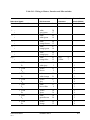
Item
Problem
Corrective Action
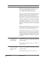
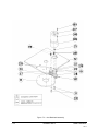
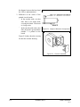
the gripper fingers closed. Screw the lead screw (94)
with the coupling portion attached, clockwise into part
(105), as tight as possible. Now release the gripper
fingers.
2. Refit the motor by aligning the coupling fitted to the
motor output shaft together with the plastic coupling
portion attached to the metal portion attached to the lead
screw (94).
3. When all the coupling sections are aligned and
attached, turn the motor body until the holes in the plate
(112) align with those in part (91). Reinsert and tighten
the three bolts which you loosened at the beginning of
the procedure.
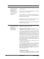
14. Motor turns constantly
in one direction after a
move axis command is
given.
Press the controller RESET button.
If pressing the RESET switch stopped the motor’s
rotation, the problem is probably due to the encoder, or
the encoder circuitry in the controller. Check the square
wave from both phototransistors while the motor is
rotating.
15. Motor turns constantly
in one direction when
POWER and MOTOR
switches are turned on.
The fault probably lies in the power transistors (on the
PC 200N and PC 200P boards) or in the opto-isolators
(ICs U45-U48) on the main circuit board (PC 010)).
Contact your agent.
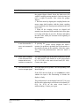
16. The controller does not
receive an input signal.
Short the input port to ground. The corresponding LED
should light up.
If the LED does not light up, use SCORBASE to check
whether the input is not functioning or whether the
display is faulty.
The problem may be in the display board (PC 310) or in
the flat cable connecting it to the main circuit board (PC
010). Or, ICU9 on the main circuit board is
malfunctioning. Contact your agent.
USER’ S MANUAL
9211
SCORBOT-ER III
6-11