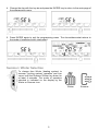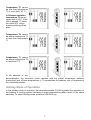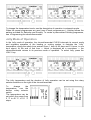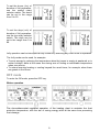
1
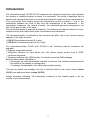
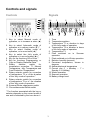
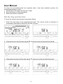
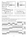
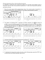
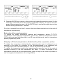
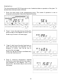
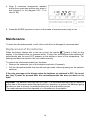
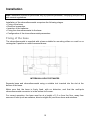
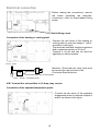
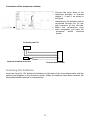
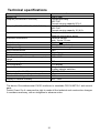
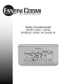
Weekly Chronothermostat
CH150 / CH151 / CH152
CH150-16 / CH151-16 / CH152-16
CONTENTS
Introduction.................................................................................................................................2
Controls and signals ..................................................................................................................3
Controls ................................................................................................................................. 3
Signals ................................................................................................................................... 3
User Manual...............................................................................................................................4
Set the day and the time....................................................................................................... 4
Summer / Winter Selection................................................................................................... 5
Modes of operation ............................................................................................................... 6
Manual mode of operation.................................................................................................... 6
Automatic Mode of Operation............................................................................................... 6
Holiday Mode of Operation................................................................................................... 7
Jolly Mode of Operation........................................................................................................ 8
OFF mode ............................................................................................................................. 9
Preset Programmes ............................................................................................................ 10
Programming the chronothermostat .................................................................................. 11
Display of the temperature detected by the separate probe ............................................ 12
Statistics .............................................................................................................................. 13
Maintenance.............................................................................................................................14
Replacement of the batteries ............................................................................................. 14
Installation ................................................................................................................................15
Fixing of the base................................................................................................................ 15
Electrical connection ........................................................................................................... 16
Inserting the batteries ......................................................................................................... 17
Fixing the chronothermostat to the base ........................................................................... 18
Configuring the chronothermostat...................................................................................... 18
Technical specifications...........................................................................................................21
1
Introduction
The chronothermostat CH150/151/152 measures the ambient temperature and regulates
the heating or conditioning plant to which it is connected. The mode of operation can be
chosen from among those preset, or can be personalised to meet one’s own requirements.
The conveniently sized display shows the temperature profile or pattern — that is, the
relationship between the time of day and the temperature to be maintained — the
temperature measured, the relative humidity, the calculated perceived temperature, the
time of day and the day of the week.
The chronothermostat is powered by batteries. The settings and data are stored in a nonvolatile memory that retains them even if the batteries are exhausted.
The chronothermostat is available in two versions that differ only in the current carrying
capacity of the relay contacts:
• CH150 Chronothermostat with 5 A relay.
• CH150-16 Chronothermostat with 16 A relay
For chronothermostats CH150 and CH150-16 the following external interfaces are
available:
• Separate temperature probe;
• Telephone activator for fixed phone line; this allows remote control from a DTMF
(multitone) keyboard;
• Telephone activator with GSM modem, for remote control by SMS message.
Both activators make it possible to:
• Interrogate the chronothermostat remotely to discover the ambient temperature and
the status of the heating or cooling plant;
• To manage the operation of the chronothermostat remotely.
The various models are available not only in white but also in the colours silver (series
CH151) and anthracite black (series CH152).
Unless otherwise indicated, the instructions contained in this manual apply to all the
models of chronothermostat.
2
Controls and signals
Controls
Signals
11
10
9
8
7
1
2
3
4
5
6
14
13 12
1
2
11
10
3
4
5
9 8 7 6
1. Time
2. Temperature pattern
3. Temperature T1 or duration in days
of the Jolly mode of operation
4. Temperature T2 or duration in hours
of the Jolly mode of operation
5. Temperature T3
6. Plant switched on in Summer
operation
7. Plant switched on in Winter operation
8. Relative humidity (percent)
9. Perceived temperature, shown in
degrees
10. Ambient/external temperature
11. Current day (1 = Monday … 7 =
Sunday; 8 = Holiday)
12. Winter operation
13. Summer operation
14. Battery charge level
1. Key to select Manual mode of
operation, or to increase a value (▲)
*
2. Key to select Automatic mode of
operation or to reduce a value (▼) *
3. Key to select Holiday mode of
operation, or to move back (◄) *
4. Key to select the Jolly mode of
operation or to move forward (►) *
5. Key for the functions Off or Enter *
6. Key for functions Programming, or
Copy or Display Statistical Data *
7. Rotary
selector
switch
for
temperature correction: T1, Manual
Temperature, Jolly Temperature and
Frost Protection Temperature*
8. Rotary selector switch for correction
of temperature T2 or of the duration
of the Jolly mode of operation *
9. Rotary selector switch for correction
of temperature T3 or of the duration
of the Jolly mode of operation
10. Summer/Winter changeover switch
11. Chronothermostat Reset switch
* The function associated with the key or
selector depends on the current mode of
use and is indicated by the icon above it
3
User Manual
To bring the chronothermostat into operation after it has been installed, perform the
following operations in order:
1. Set the day of the week and the time of day.
2. Select Summer or Winter operation.
3. Select the mode of operation.
Set the day and the time
To enter the current time and day, proceed as follows:
1. Enter the main page of the programming menu. The current mode of operation is
momentarily interrupted. Select the “set time” function.
2. Change the hour with the keys ▲ and ▼ and move to the minutes with the key ►.
3. Change the minutes with the keys ▲ and ▼ and move to the day with the key ►.
4
4. Change the day with the key ▲ and press the ENTER key to return to the main page of
the programming menu.
5. Press ENTER again to exit the programming menu. The chronothermostat returns to
the mode of operation briefly interrupted.
Summer / Winter Selection
To change from Winter (heating system) to
summer (cooling system) operation and vice
versa, hold the Summer/ Winter key down for
at least 4 seconds. The mode of operation
selected is indicated on the display by the
Winter or Summer icon.
Winter
5
Summer
Modes of operation
The chronothermostat CH150/151/152 has 4 different modes of operation — Manual,
Automatic, Holiday and Jolly — and OFF mode.
Manual mode of operation
In the Manual mode of operation, the chronothermostat regulates the operation of the
heating or cooling plant to maintain the same temperature always. To select Manual, press
the key MAN.
The temperature can be
altered during operation
by adjusting the bottom
rotary selector switch on
the right side of the
chronothermostat.
The
temperature can be set
within the range from 2°C
to 40 °C, in 0.1 °C steps.
Automatic Mode of Operation
In the Automatic mode of operation, the chronothermostat regulates the operation of the
heating or cooling system following the patterns set for the various days of the week. To
select Automatic, press the AUTO key.
The three temperature levels used can be modified during operation by means of the rotary
selector switches on the right hand side of the chronothermostat.
6
Temperature T3 cannot
be less than temperature
T2 or more than 40 °C.
In Summer operation,
temperature T3 has an
upper limit of 30°C. If this
limit is passed, T3 takes
the value OFF, which
means switching off the
plant.
Temperature T2 cannot
be above temperature T3
or less than temperature
T1.
Temperature T1 cannot
be above temperature T2
or less than 2 °C.
In the absence of any
personalisation, the Automatic mode operates with the preset temperature patterns
memorised (see «Preset programmes »). To personalise the patterns, see «Programming
the chronothermostat».
Holiday Mode of Operation
In the Holiday mode of operation, the chronothermostat CH150 regulates the operation of
the heating or cooling system following a single temperature pattern which is the same
each day. To select Holiday mode, press the HOLIDAY key.
7
To change the temperature levels, see the description of operation in automatic mode.
When the preset programmes are used (see «Preset programmes »), Holiday follows the
pattern provided for Saturday and Sunday. To create a personalised Holiday programme,
see «Programming the chronothermostat».
Jolly Mode of Operation
In the Jolly mode of operation, the chronothermostat CH150 interrupts its current mode
and regulates operation of the heating or cooling system to maintain the “Jolly”
temperature during the whole time entered (from 1 hour to 99 days and 23 hours, in one
hour steps). At the end of that time — which is displayed as a countdown — the
chronothermostat returns to its previous mode of operation. To select Jolly, press the
JOLLY key.
The Jolly temperature and the duration of Jolly operation can be set using the rotary
selector switches on the right of the chronothermostat.
To
change
the
temperature, use the
bottom rotary selector
switch.
The temperature can be
set within the range from
2 °C to 40 °C, in 0.1 °C
steps.
8
To set the hours («h») of
duration of Jolly operation,
use the central rotary
selector switch. The hours
can be set in the range
from 0 to 23.
To set the days («d») of
duration of Jolly operation,
use the top rotary selector
switch. The days can be
set in the range from 0 to
99.
Jolly operation can be interrupted at any moment by selecting any other mode of operation.
The Jolly mode can be used, for example:
To save energy by reducing the temperature when the house is empty at weekends or in
winter holidays, while at the same time being sure of finding a comfortable temperature
when one returns;
To extend evening heating or cooling beyond the usual times, for example, when there
are guests in the house.
OFF mode
To enter the Off mode, press the OFF key.
Winter operation
The chronothermostat regulates operation of the heating plant to maintain the frost
protection temperature, with the aim of saving energy while at the same time preventing
frost damage.
9
The
Antifreeze
Temperature can be set in
the range from 2 °C to 7
°C, in 0.1 °C steps, using
the bottom rotary selector
switch. If a temperature of
less than 2 °C is set, the
plant
switches
off
completely
and
frost
protection is lost.
Summer operation
The plant switches off completely and the wording OFF appears on the display, with no
temperature pattern.
Preset Programmes
The chronothermostat CH150 is supplied with two preset programmes, one winter and the
other summer, so that it can be put into operation quickly.
Winter programme – weekdays (Monday to Friday)
Winter programme – weekends (Saturday, Sunday and Holiday programme)
Summer programme (For every day of the week and Holiday programme)
10
Programming the chronothermostat
It is possible to personalise the temperature patterns for Automatic and Holiday modes to
bring them into line with one’s personal requirements. To enter new temperature patterns,
proceed as follows.
1. Enter the main page of the programming menu; the current mode of operation is
temporarily interrupted. Select the temperature pattern personalisation function.
2. The pattern for Monday (DAY 1) appears for Winter operation (icon ). Use keys ◄
and ► to move the flashing segment of the bar graph on the hour for which one wants
to change the temperature. Each segment is equivalent to half an hour. To change the
patter for Summer operation (icon ) press the Summer/Winter key on the left side of
the chronothermostat.
3. Use keys ▲ and ▼ to change the temperature settings (T1, T2 or T3).
4. To duplicate the temperature pattern directly on the following day, press the COPY key
(to personalise each day separately see point 5).
11
5. Press the ENTER key to move to the next day and repeat the steps from point 2 for the
other days of the week; the Holiday pattern is indicated as DAY 8. To return to the main
page of the programming menu, use the ENTER key to scroll all the eight days or keep
the ENTER key pressed for 3 seconds.
If no key is pressed for more than 3 minutes, the chronothermostat returns to the mode of
operation in use previously.
Restoration of the preset parameters
To restore the preset temperature patterns and temperature values (T1-T2-T3Temperature used in Manual, Temperature used in Jolly, Antifreeze temperature used in
OFF mode) press and hold down the ▲ and ▼ keys simultaneously when in temperature
pattern programming mode.
Display of the temperature detected by the separate probe
To display the temperature detected by the separate probe (only if configured as an
external or floor probe) it is essential for the chronothermostat to be configured (see
<<configuration of the chronothermostat>>) and for the probe to be connected.
To display the temperature read by the separate probe, press the key for the mode of
operation currently in use (the temperature will flash). To return the display to the
temperature detected by the chronothermostat, press the key for the mode of operation in
use once again (the temperature will no longer flash).
12
Statistics
The chronothermostat CH150 provides a set of statistical data on operation of the plant. To
access these data proceed as follows:
1. Enter the main page of the programming menu. The mode of operation in use is
temporarily interrupted. Select the statistics function.
2. Page 1: hours the plant was on during the
previous day (in the diagram 6 hours). Use
the ► key to move to the next page.
3.
Page 2: total hours the plant has been on
since first brought into operation (in the
diagram 16 hours). Use the ► key to
move to the next page.
Press the ▲ and ▼ keys simultaneously
to zero the total hours on.
4. Page 3: minimum temperature reached
during the current day and the hour when it
was reached (in the diagram 15.8 °C at
time 03.15). Use the ► key to move to the
next page.
13
5. Page 4: maximum temperature reached
during the current day and the hour when it
was reached (in the diagram 22.5 °C at
time 21.08).
6. Press the ENTER key twice to return to the mode of operation previously in use.
Maintenance
To clean the chronothermostat, a soft cotton cloth with no detergent is recommended.
Replacement of the batteries
When the battery charge falls to too low a level, the symbol
starts to flash on the
display. If the batteries are not replaced within 15 days, the chronothermostat switches off
automatically and the word OFF appears on the display in place of the temperature. The
settings and data are stored in the non-volatile memory.
To remove the chronothermostat from the base:
• Remove the connector jack of the telephone activator (if present);
• Pull the chronothermostat from the left and right sides, without pressing on the selector
switches.
If the only message on the display when the batteries are replaced is OFF, the round
key [key 5] must be pressed after the chronothermostat has been put back on its
base.
Important. The batteries normally last for a year. It is recommended that they be replaced
at the start of the season when the plant will be in operation, to prevent the batteries going
flat when no one is around, for example during the year-end holiday period.
The used batteries should be disposed of in containers for the purpose.
14
Installation
Note. Installation should be performed only by qualified personnel, complying scrupulously
with current regulations.
Installation of the chronothermostat comprises the following stages.
• Fixing of the base
• Electrical connection.
• Insertion of the batteries.
• Fixing the chronothermostat to the base.
• Configuration of the chronothermostat parameters.
Fixing of the base
The chronothermostat is supplied with a base suitable for mounting either on a wall or on
rectangular 3-position or round recessed boxes.
INTERAXIAL HOLE DISTANCES
Separate base and chronothermostat using a suitable tool inserted into the slot at the
bottom of the base.
Make sure that the base is firmly fixed, with no distortion, and that the multi-pole
chronothermostat connector is in the bottom left corner.
For correct operation, the base must be at a height of 1.5 m from the floor, away from
sources of heat (such as radiators, direct sunlight etc) and from doors and windows.
15
Electrical connection
Before making the connections, remove
the shield protecting the terminals,
conserving it with its cross-headed fixing
screw.
Shield fixing screw
Connection of the heating or cooling plant
Connect the two wires of the heating or
cooling plant to terminal clamps 1 and 2,
as shown in the figure.
The terminals can take flexible conductors
with a maximum section of 2.5 mm2.
Terminal 4 is free and can be used for
signalling or other purposes.
Neutral
Phase
Attention: Check that the relay load does
not exceed the value shown in the
«Technical Specifications».
4
1
2
Load
Chronothermostat relay terminal board
Load = Burner – Circulation pump
N.B. Terminal 4 is not available in 16 Amp relay version
Connection of the separate temperature probe
Connect the two wires of the separate
temperature probe to terminal clamps A
and B, as shown in the figure.
16
Connection of the telephone activator
Connect the three wires of the
telephone activator to terminal
clamps 1, 2 and 3, as shown in
the figure.
Alternatively, the activator can be
connected through the 3.5 mm
jack connector on the left side.
When the connections have
been completed, put back the
protective
shield
removed
earlier.
Terminal board CTx
1 2 3
3
2
1
B
A
Separate temperature sensor
Terminal board CH150
Inserting the batteries
Insert two long life 1.5V alkaline AA batteries in the back of the chronothermostat, with the
positive and negative in the directions shown. When the batteries have been inserted, the
chronothermostat switches on automatically.
17
Fixing the chronothermostat to the base
Fix the chronothermostat to the base by manual pressure, making sure that the multi-pole
connector is inserted correctly. The chronothermostat connection is snap-in.
Configuring the chronothermostat
Note: Configuration must be performed only by qualified personnel.
By configuring the chronothermostat one can personalise its operating parameters. To
access the configuration programme, proceed as follows.
1. Press the SET / PROG key [key 6]. The current mode of operation is temporarily
interrupted and is resumed automatically when programming ends.
2. Press and hold down the SUMMER / WINTER key [key 10] for about 5 seconds.
The
configuration
SCRITTA
parameters,
each
of which
VALORE
has its own preset value,
INDICE
are identified on the display
by a number and writing. To
change the values of a
parameter use the keys ▲
[key 1] and ▼ [key 2]; to
move
between
the
parameters, use the key ►
[key 4].
To return to the initial page of the programming menu, press the ENTER key [key 5], which
saves the changes in the memory.
If no key is pressed for 3 minutes, the chronothermostat exits the configuration programme
and returns to the mode of operation previously in use, without saving.
To eliminate the changes made and restore the preset values of the configuration
parameters, press keys ▲ [key 1] and ▼ [key 2] simultaneously and hold them down for
about 4 seconds.
18
Number
1
2
Parameter
Type of board connected
Temperature scale
3
Type of regulation
3A
3A
Thermal differential
Regulation band
3B
Period of regulation
Per
4
Configuration of the separate
temperature probe
Floor temperature limit
Correction
of
ambient
temperature
Optimisation
Maximum
duration
of
optimisation (in hours)
Pump gripping prevention
Software version
Sect
4A
5
6
6A
7
8
Writing
COn
CELS
or FHAr
Std or
ProP
DIFF
bAnd
Values
rEL / rAd / --°C / °F
Preset
none
°C
Std / ProP
Std
LO
2 °C
OPt
OPtH
HI / LO
1 °C – 4 °C
(step 0.1°C)
5 / 10 / 20
minutes
--- / FLO / In /
Out
15 °C – 45 °C
from -4.0 °C
to +4.0 °C
ON/OFF
1h – 5h
Pu
SOFt
ON/OFF
Xxx
tFLO
Corr
10 minutes
--27.0 °C
0.0 °C
OFF
2h
OFF
xxx
Type of board connected
The chronothermostat can verify whether the base is connected. If it is not, the short lines
are displayed, whereas if it is connected the wording rEL appears. In the radio frequency
version, the writing rAd is displayed.
Temperature scale
Selects the scale, degrees Celsius (centigrade) or Fahrenheit, that will be used for display
of all the temperatures. If the Fahrenheit scale is used, the temperatures can range from
0.0 °F to 99.9 °F.
Type of regulation
Selects the mode of temperature regulation: with differential (Std) or proportional (ProP).
This parameter is used for heating only.
Thermal differential
Imposes the thermal differential when the mode of temperature regulation with differential
has been chosen. Choosing the differential appropriately, on the basis of the thermal
inertia of the heating plant, one avoids continuously switching on and off (hunting). The low
thermal differential (LO) is recommended for heating plant with radiators, the high one (HI)
for plant with Fan-Coils.
Regulation band
Select the appropriate value according to the thermal gradient of the plant (wide band for
steep gradients – narrow band for low gradients).
19
Period of regulation
Imposes the duration of the regulation cycle (period on + period off) when the proportional
temperature regulation mode is chosen. Select 5 minutes for low inertia plants (such as fan
coils), 10 minutes for medium inertia plants (such as aluminium radiators), 20 minutes for
high inertia plant (such as cast iron radiators).
Configuration of the separate temperature probe
It is possible to connect a separate temperature probe to the chronothermostat; its
functioning is determined by this parameter.
• Probe excluded (---): even if the probe is connected, the temperature value it detects is
not utilised.
• Floor probe (FLO): when the temperature detected by the probe reaches the value
imposed in the parameter Floor temperature limit the plant is switched off independently
of the temperature detected by the chronothermostat.
• Ambient probe (In): regulation of the plant is based on the temperature value detected
by the separate probe. This temperature appears on the display in place of that detected
by the internal probe within the chronothermostat. The separate ambient probe is used
when the chronothermostat is necessarily situated in a position other than that whose
temperature one wants to control;
• External probe (Out): does not influence regulation of the plant and serves simply to
provide information on a second temperature, for example the outside temperature.
Floor temperature limit
Imposes the limit value for the temperature read by the separate probe which switches off
the plant when the floor probe is used (for underfloor heating plant).
Correction of the ambient temperature
Makes it possible to add or subtract an offset from the temperature measured by the
chronothermostat.
Optimisation
Calculates the advance switch-on time necessary to achieve the desired temperature at
the time of day set, taking account of the thermal inertia of the plant. This optimisation is
applied only to the first switch-on of the day, that is on the first programmed step from one
temperature to a higher one.
Maximum duration of optimisation
Imposes the maximum duration (expressed in hours) for the advance switch-on calculated
by the optimisation.
Pump gripping prevention
Switches the plant on for 1 minute a day (at h 23.58), making the water circulation pump
rotate, with the aim of preventing it from gripping. It comes into operation only if the plant
has never been switched on during the day.
20
Technical specifications
Power supply
Battery life
Outputs (CH150/CH151/CH152)
Outputs (CH150-16/CH151-16/CH152-16)
Inputs
Electrical connections
Insulation
Protection degree
Settings storage
Micro disconnection
Software
Temperature regulation range
Frost protection temperature
range
Maximum temperature
Local signalling
Local controls
regulation
2 alkaline AA 1.5 V batteries
Over a year
1 single pole relay
250 V AC
Current carrying capacity 5(3) A
1 single pole relay
250 V AC
Current carrying capacity 16 (4) A
Telephone activator
Separate temperature probe
Terminal clamps
Jack, 2-pole 3.5 mm
Double
IP20 (normal pollution)
Non-volatile memory
1BU
Class A
2 °C – 40 °C
2 °C – 7 °C
T45
LCD display
7 keys
3 rotary selector switches
155 X 91 X 20
10 m max
4 K/h
20% - 90%
Dimensions (L x H x W)
Distance for separate temperature probe
Standard thermal gradient
Display of relative humidity
The device Chronothermostat CH150 conforms to standards CEI EN 60730-1 and second
parts.
Fantini Cosmi S.p.A. reserves the right to make all the technical and construction changes
it considers necessary, with no obligation to advance notice.
21
NOTES:
-----------------------------------------------------------------------------------------------------------------------------------------------------------------------------------------------------------------------------------------------------------------------------------------------------------------------------------------------------------------------------------------------------------------------------------------------------------------------------------------------------------------------------------------------------------------------------------------------------------------------------------------------------------------------------------------------------------------------------------------------------------------------------------------------------------------------------------------------------------------------------------------------------------------------------------------------------------------------------------------------------------------------------------------------------------------------------------------------------------------------------------------------------------------------------------------------------------------------------------------------------------------------------------------------------------------------------------------------------------------------------------------------------------------------------------------------------------------------------------------------------------------------------------------------------------------------------------------------------------------------------------------------------------------------------------------------------------------------------------------------------------------------------------------------------------------------------------------------------------------------------------------------------------------------------------------------------------------------------------------------------------------------------------------------------------------------------------------------------------------------------------------------------------------------------------------------------------------------------------------------------------------------------------------------------------------------------------------------------------------------------------------------------------------------------------------------------------------------------------------------------------------------------------------------------------------------------------------------------------------------------------------------------------------------------------------------------------------------------------------------------------------------------------------------------------------------------------------------------------------------------------------------------------------------------------------------------------------------------------------------------------------------------------------------------------------------------------------------------------------------------------------------------------------------------------------------------------------------------------------------------------------------------------------------------------------------------------------------------------------------------------------------------------------------------------------------------------------------------------------------------------------------------------------------------------------------------------------------------------------------------------------------------------------------------------------------------------------------------------------------------------------------------------------------------------------------------------------------------------------------------
22
Fantini Cosmi S.p.A.
Via dell’Osio, 6 20090 Caleppio di Settala MI
tel. 02 956 821 - fax 02 9530 7006
e-mail: [email protected]
http://www.fantinicosmi.it
Technical support: [email protected]
23