1
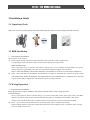
DVR-HXx92 EX-SDI video recorder user manual ` EX-SDI DVR OPERATION MANUAL FOREWORD Thank you for using our products, we will be dedicated to provide you with our best quality service. Contents of this user manual is only for reference, subject to updates without notice, updates will be added in the new version of the manual, and will be available for download on the company's website Download Center. Description in this user manual may contain technical inaccuracies or typographical errors, and sincerely hope you can give us feedback in a timely manner, in order to enrich and improve the user manual and our products. EX-SDI DVR 1 Precautions Here are on the correct usage of the product, risk prevention, protect loss of property, please be sure to follow. Please position the DVR allows the temperature and working temperature range. Please do not install in a place of humidity, dust or soot. Please install this product horizontally and guard against falling for this product. Please install in a well-ventilated place, do not block the airflow to the device. Please do not rotate the container objects filled with liquids on the device. Please do not place other devices in the above. Please do not disassemble this product at will. Select hard disk recommended by the manufacturer, suitable for DVR requires hard drive. 2 Declaration All products is subject to physical, manual is for reference only. The product descriptions may contain technical inaccuracies or typographical errors. Products or programs described in the product description may be improved or updated at any time, subject to upgrading without prior notice. This product specifications screenshots in the book are not the same machine, for presentation purposes only. If you have any questions or for the latest programs and supplements description documentation please contact the Service Department of the company. ` EX-SDI DVR OPERATION MANUAL TABLE OF CONTENTS FOREWORD EX-SDI DVR PROFILE ........................................................................................................................................................1 1 Product Overview ....................................................................................................................... 1 2 Product Features ........................................................................................................................ 1 3 Installtion Gurde......................................................................................................................... 2 PART 1 DVR LOCAL BASIC OPERATION ....................................................................................................................... 3 1 Basic Operation .......................................................................................................................... 3 2 Login ........................................................................................................................................... 7 3 Preview....................................................................................................................................... 7 4 Video Mode ................................................................................................................................ 8 5 System Configuration ................................................................................................................. 8 6 Video Configuration ................................................................................................................... 9 7 Video Plans ............................................................................................................................... 11 8 Video Search ............................................................................................................................ 12 9 Video Backup............................................................................................................................ 14 10 Network Configuration ........................................................................................................... 15 11 Alarm Settings ........................................................................................................................ 16 12 PTZ Control ............................................................................................................................. 17 13 Voice Talkback ..............................................................................................................................19 PART 2 PC REMOTE MONITORING .........................................................................................................................20 1 PC Remote Monitoring Profile.................................................................................................. 20 2 Network ................................................................................................................................... 20 3 PC Client VSS WEB Management.............................................................................................. 21 4 PC Client CMS 2015 Management ........................................................................................... 27 PART 3 HDIVS MOBILE REMOTE MONITORING ..........................................................................................................43 1 HDIVS Profile ............................................................................................................................ 43 2 HDIVS Installation ..................................................................................................................... 43 3 login Interface.................................................................................................................................44 4 Device Management ................................................................................................................ 47 DEVICE MANAGEMENT ............................................................................................................................................... 59 APPENDIX...............................................................................................................................................................60 ` EX-SDI DVR OPERATION MANUAL EX-SDI DVR PROFILE 1 Product Overview This products is a specially designed for video surveillance field designer of video coding and records of products, combining H.264 of video compression, and big capacity hard disk storage, and TCP/IP network, and Embedded LINUX operating system and the other various advanced electronic information technologies. It realize high quality, and low yards rate, long transmission reach 500 meters SDI signal of audio and video. Recording characteristics and outstanding system stability, powerful of network service greatly improve the ability of network data and remote control. 2 Product Features Real-time monitoring With composite video interface, supports TV, VGA, or HDMI output simultaneously. Compression function Using the H.264 video compression standard and G.711 Audio compression standard, maximum support 1920*1080 resolution code. Recording function Supports timing, alarm linkage, such as various recording modes, support SATA hard drive, and local hard S.MA.R.TR technology, equipped with USB interface for backup of local drive or network function. Playback Functions Can realized by multiple criteria in searching video for local and network playback, support simultaneous playback of multi-channel video, such as fast and slow motion, frame playback, and other playback mode. Playback can display the accurate time of events. camera control and Alarm Support remote camera control: equipped with multi-channel audio alarm input interface, motion detection, video loss, video masking, alarm function. Communication Interface USB2.0 high speed interface or the SATA interface, external multiple backup devices with standard Ethernet interfaces, Plug-and-play under various network conditions. Network Function Supports TCP/IP, UDP, RTP/RTSP, and DHCP, PPPOE, DDNS, NTP and other rich network protocol, support network real-time monitoring, playback, control and management functions; a built-in WEB Server, which make it possible to visit directly through the browser. Operation Support front panel operation, IR remote control, mouse and many other methods, a simple and intuitive graphical interface. -1- ` EX-SDI DVR OPERATION MANUAL 3 Installation Guide 3.1 Unpacking Check When you receive the product, please check that following in the same box as the packing list for the inventory. 3.2 HDD Installation Preparation for Installation Please prepare one screwdriver. Note: Various models of hard drive disk and number limit of hard drive disks is subject to the corresponding product specification sheets, and hard drive capacity max support 8TB. HDD installation steps. Step 1: Discharge screws on the side of the chassis, open the above cover of chassis, then put HDD in the specific location which can support HDD. After that, fix screws between HDD and support with screwdriver. Step 2: connect the hard drive data cables and power cord, and then cover the cover to the chassis with screws. Note::Select hard disk recommended by the manufacturer, suitable for DVR hard drive. After booting, the system will automatically format the hard disk, and original data on your hard disk may be completely lost. Hard disk capacity and recording configurations will affect the longest recording video time. 3.3 Wiring Operation Preparation for Installation Please prepare video cameras, monitors, video cables, network cables, mouse, and power cable. Connection Steps:: Firstly, put the DVR to show its interface facing to you, then connect BNC cables (video signal source) with BNC interface of DVR. Secondly, connect the DVR with monitoring device via HDMI / VGA and other video cables. Thirdly, connect the DVR with router via RJ45 interface. On the other side, connect USB mouse with DVR. Note::If you need an external alarm devices, or pan/tilt, please refer to related content settings. Please carefully check the connection of DVR with other device before inputting power, and whether there is enough power for DVR or other device. -2- ` EX-SDI DVR OPERATION MANUAL PART 1 DVR LOCAL BASIC OPERATION 1 Basic Operation 1.1 HDD Usage When it's the first time to operate the device, please install HDD before usage. E-family support 2 SATA hard drives, when the hard drive is connected, place the seams close to the DVR hard drive interface side. Note: if there is an error prompt during active recording function after recording configuration settings are finished according to the manual, please format HDD. If it show unrecognized HDD, please kindly check the power consumption of power adaptor whether it reach the consumption in operation with HDD, or check whether HDD have quality problems. 1.2 USB Connection E-series two USB interface on the back panel, for a mouse, USB, WIFI module. 1.3 Mouse Operation When real time monitoring mode, click the left mouse button to access the main menu: If the user has not logged on to the system, you pop up a password entry box. During real-time monitoring, click the left button to enter the main menu. If user didn't login yet, pop-up of login interface will come out. When the cursor is on the menu icon, click the left button to enter the menu. Operate some execution controls or change the status of checkbox in motion detection. When click the combobox, it will pop out a spinner. During PTZ 3D control, press the left button and drag the cursor to the right corner, it will active zoom in. function. On the contrary, the oppsite operation will active zoom in function. The effect in user manual is just for reference. Detailed instructions refer to section 12 in Part 1. Double click the left button Operations of select, confirm and open. For example, double-click will playback one recording video. When real-view monitoring in multi-channel mode, double-click will let one channel shown in full screen. Then user can recover multi-channel mode by double click again. Click the right button During real-time monitoring mode, this operation will pop out right-click menu. -3- ` EX-SDI DVR OPERATION MANUAL When it display menu or sub-menu mode, this operation will make it return to the upper menu without saving. Turn the wheel Turning the mouse wheel to increase or decrease numerical values in digital checkbox. . Switch the option of the combo box. Flip up and down list box. Scroll back and forth to change the effect of PTZ 3D zoom function. Mouse movement Select the current coordinate control or control a particular move. Mouse drag Marquee motion detection area. Marquee locale regional coverage. Marquee zoom 3D PTZ control function. 1.4 Input Method In the input box, you can choose to enter numeric characters, symbols, English, Chinese, left mouse button click on the character to choose it: English input interface: Chinese input interface: Numbers input interface: Special symbols Interface: -4- ` EX-SDI DVR OPERATION MANUAL 1.5 Boot DVR is correctly installed and plugged in, the power led is lit, video recorder will automatically turn on. Show slightly different under different types of device power state , please refer to the front panel section of this article. DVR boot process will automatically detect the device hardware state, boot process takes about 20 seconds. Power-on complete devices after the buzzer was given a "beep" tone, and enter the screen real-time video surveillance state, equipment operation or configuration can be at this time. Please refer to 4.2 main menu introduction and subsequent introduction. If the start-up time within the video to set the time, the system will automatically start a scheduled recording function. Note: Please use the DVR power supplied, you may not use other types of branded power supply instead of the original power supply. 1.6 Shutdown Turn off the device, soft and hard switches. Soft-switch, go to "main menu" > "shut down the system" select "close"; hard switching, hard and directly pull out the power cord when the switch is off. (Hard switching may result in data loss, please use caution) reminder: replace the button battery on the motherboard you need to save the configuration, or configuration information will be lost. During shutdown, press the front panel opening key turn off the device. Enter the "main menu"-"shut down the system"-select "device off" Figure 1-1 Note: replace the hard disk operation should be off the device and disconnect the power before proceeding. 1.7 Power Recovery When video card video under operating conditions, if power to the system is cut off or been forced to shut down, reconnected power, VCRs will be automatically saved before powering down the video and automatically restore power before working status to continue to work. -5- ` EX-SDI DVR OPERATION MANUAL 1.8 Screen Icon 1.8.1 Status Icons :This flag is displayed on the channel screen monitor channel video. :Channel video loss occurs, the channel screen display this flag. :Dynamic detection occurs, the channel screen display this flag. :The channel is monitoring the locked state, this flag is displayed on the channel screen. : Allows the screen to switch polling. 1.8.2 Operator Logos :Enable box unchecked. :Enabled box is checked state. :Transferred out of the drop-down menu :Determined to modify the settings / menu to enter。 :Set / cancel to cancel the change to enter the menu. : To set the parameters. :Save the current set of parameters. :Default factory settings, modify parameters, clicking on the button to return to the last set of parameters. :The current set of parameters is applied to the system. :The current set of parameters are copied to the other channel. :Enter the parameter configuration menu. :Selection and configuration of the alarm, the processing operation of the video detection trigger. -6- ` EX-SDI DVR OPERATION MANUAL 2 Login After equipment starts normally, you need log in the system, which provides corresponding functions according to user authority. Note: One preset administrator account exists, username is admin, password is “empty”,user can change password, but cannot change the authorities. Administrator can add, delete or configuration user parameter. Figure 1-2 Password protection: An alarm beep popup when password was inputted incorrectly for continuous 3 times, and system will be locked after password was inputted incorrectly for continuous 5 times. After 30 minutes or reboot the DVR system will be unlocked by itself. For security, the password should be modified as soon as you first using the DVR. 3 preview Device boots into monitor screen in real time, at each scene there is superimposed on the date, time, channel names, there is a line at the bottom of the screen says video and alarm status icon for each channel. Also available through the front panel, the remote control or the right mouse button and double-click the left button screen switch operation. Preview icons are as follows: Channel record sign Video missing Channel motion detection sign The channel monitoring locked sign Channel roundrobin switch sign Channel audio switch sign Graph 1-1 -7- ` EX-SDI DVR OPERATION MANUAL 4 Record Model "Preview interface" > "right-click menu" > "video mode", enter the video control interface set video status. Figure 1-3 Videos record model total 3 status: auto, manual and off; Auto: depending on settings (normal, motion detection and alarm) the video type and video recording time; Manual: no matter what channel is currently in a State, select "manual", the corresponding channel full manual video; Off: no matter what channel is currently in State, select "Off", the corresponding channel to stop the video. 5 System Configuration Enter the "main menu" > "system setting" > "system configuration" settings to configure the system parameters. Figure 1-4 -8- ` EX-SDI DVR OPERATION MANUAL [System Time]: Change the DVR system time Note: after you change the system time need to click Save after key save individual system time. [Date Format]: Select the date display format. [Daylight saving time]: Daylight saving time check box is checked, and then click on the settings button, set the start and end of daylight time. [Date]: as the date format separator. [Time Format]: includes 24-hour and 12-hour. [Language choice]: Switches the system menu language (different models have different language options). [HDD Full]: you can choose to either stop or cover. Stop recording conditions are: current working disk is overwritten, or write my current working disk full, and the next non-empty hard disk, it will stop recording; overriding condition is: write my current working disk full, and the next hard disk is not empty, it loops over the first video file. [Video Length]: You can set the length of each video files, the default is 60 minutes, a maximum of 120 minutes. [DVR NO.]: It is used more than a remote control or control panel remote control DVR, only when I press the add key on the remote control and enter the remote address and have the same address with a corresponding native DVR number for remote control operation. [Video Standard]: select the video standard, PAL/NTSC (must match the camera system). [Auto Logout]: menu ahead of time 0-60, 0 can be set to not set the standby time, if you set the time, after the idle during this time, the system automatically logs off the current logged on user, users to action menu you need to log in again. 6 Video Configuration Video setting contains the basic configuration of the video and the video plan. Including videos of the channel is mainly video resolution, frame rate, bit rate, and set the parameters such as channel title; video program you are automatically recording mode under the channel in different time periods, recording different States (normal, motion detection and alarm) video . Figure 1-5 -9- ` EX-SDI DVR OPERATION MANUAL Basic Configuration After entering the video configuration-basic configuration, interface appears. [Channel]: select the channel you want to set. [Encode Mode]: select the channel you want to set. [Resolution]: The main stream types for resolution D1/CIF optional. Channel, different resolution, frame rate, frame rate that corresponds to the setting that corresponds to the scope is different. Channel expansion resolution can support the CIF/QCIF. A variety of main stream parameters, users can be combined as needed. [Frame Rate]: system PAL: 1 to 25frames/sec; system NTSC: 1-30 frames/second. Note: the main stream resolution and frame rate, subject to different types of equipment and process version limit. [Bit Rate]: Includes qualified stream, variable bit-stream. Qualifier code shed encoding bit-rate can be set; variable bit-shed quality to choose quality provided 6, respectively, for the low, low, low, medium, high and maximum. [Audio]: select the primary stream/extended opening and closing States of streaming audio encoding. [Snapshot]: Click capture settings, you can set the capture mode, the picture size, picture quality, capture frequencies. [Snapshot Modes]: Trigger shot, when used with alarm, alarm picture crawl settings. [Picture Size]: Select the CIF resolution shots. [Picture Quality]: 6-speed can be set, respectively, for the low, low, low, medium, high and maximum. [Snapshot Frequency]: Setting the single-channel maximum shot frequency,/2/, respectively, 3 seconds, 4 seconds per picture, 5/6 seconds//sheets/, 7 seconds, 8 seconds; [More Configuration]: Click [settings] to enter the Setup menu and additional configurations. [Displays Channel Name]: Checkbox on the screen displays the channel name. [Display Date]: Check whether the current time is displayed on the screen. [Channel Title]: Click to access, you can drag any channel position of the title, even if you save, right-after the exit, in which case the channel where the title is changed on the monitor or the monitor will not change in the video and on the WEB interface displays the modified position. [Time Title]: After click here to enter, free to drag the time position of the title, even if you save, right-after the exit, in which case the time where the title is changed on the monitor or the monitor will not change in the video and on the WEB interface displays the modified position. [Privacy Protection]: You can preview and monitor up to 4 privacy protection regional settings, adjustable shield area of arbitrary. [Region]: Setting in the preview screen, real-time monitoring of the State, the shield region on the screen, but in networks and video files, shielded area does not exist. [Copy]: Configuration will be copied to the other channel. - 10 - ` EX-SDI DVR OPERATION MANUAL Figure 1-6 7 Record Plans [Channel]: Select the channel number. The menu will with green, yellow, red three kinds of color display the corresponding channel a week ordinary, dynamic detection and alarm three video state of time plan, can be in click on each date corresponding [Configuration]: modified. [Copy]: Configuration will be copied to the other channel. Click on [configuration] to enter the editing interface as following Figure 1-7 shown. Figure 1-7 - 11 - ` EX-SDI DVR OPERATION MANUAL Figure 1-8 [Time period]: set recording time, choice of 6 periods a day. [Regular]: For ordinary video selection is valid. [Detect]: Valid selection for dynamic detection of video. [Alarm]: After selecting the alarm linkage recording effective. 8 Video search From [Shortcut Menu]> [search], go into the playback interface. Player toolbar instructions: Button Instructions Play/pause key Every time you play this backwards, back 2 seconds Closed Quick play keys, support four times as much as quick put Slow play key ,support four times slow play Play next frame, to be suspended state Play prior frame, to be suspended state Voice Circulation play Full-screen sHOW VIDEO TYPE Graph 1-2 - 12 - ` EX-SDI DVR OPERATION MANUAL Figure 1-9 Note: Normal playback, storage equipment of hard disk video files should be set to reading and writing the disk or read-only disk. By frame playback pause playback status implemented. Special Features: [Playback]: When single screen preview or playback in full screen, can be press the left key of mouse to choose any size area in screen picture [Digital Zoom in Preview]:Click the left key of mouse in the chosen area, can zoom images broadcast this area, click the right button of mouse to exit partial enlargement picture. - 13 - ` EX-SDI DVR OPERATION MANUAL 9 Video Backup From [Main Menu]> [Backup] The video backup operation in video backup menu, (USB port external storage device) interface as shown. Figure 1-10 [Detection]: When you insert a USB external storage device can detect whether the USB device is correctly identified. If identified correctly, the list should be displayed in the corresponding device and the correct capacity. [Backup]: Tick select the USB external storage device to back up, click the [backup] into the backup interface, interface as shown Figure 1-10 Figure 1-11 - 14 - ` EX-SDI DVR OPERATION MANUAL [Format]: Clear all contents on the USB backup device. Note: It will result loss, missing all of data on the USB device. The backup operation Select video start and end time of the backup that you want, click on [add], the backup interface will comply with the conditions of the recording files to backup recording files list. Add the selected recording time can be repeated again, [Clear]: Clear backup files list. For video files that don't need to be backed up, you can remove the recording files check box. After the selection is complete, click [start], the system will automatically start the video files are backed up, and shows the time remaining. Note: Video files after backup to a USB drive, the automatically be carried to the player, you can click on the player to view the videos. 10 Network Click [Main Menu]> [Network],entry [Network] configuration menu. [IP Address]:Default 192.1681.1.88; [Subnet Mask]:Default 255.255.255.0; [Gateway]:Default 192.168.1.1. Figure 1-12 Needs to set the IP address for the device and the router in the same network segment, such as the router's IP address 192.168.1.1 subnet mask for 255.255.255.0(To use default configuration)typically ,the default gateway is the router's IP address. In the IE address bar, enter the device IP address (192.168.1.88) to LAN access equipment, if necessary in - 15 - ` EX-SDI DVR OPERATION MANUAL the public network to a remote image monitoring equipment, public network setting to reference the part 2 of the PC remote monitoring 11 Alarm Alarm configuration includes the local alarm detection and video detection in two parts. Figure 1-13 Figure 1-14 - 16 - ` EX-SDI DVR OPERATION MANUAL Video detection alerts before you do the following steps: Step 1: "main menu" > "system setting" > "alert configuration" > "video test", enter the video detection interface, as shown in Figure 11; Step 2: Select channel 1, check the dynamic test, adjustment the sensitivity level; Step 3: Setting the monitoring area, click on the "locale" SETTINGS, press and hold down the left mouse button and drag the mouse to the area delineated and can be used multiple times to delineate, delineating right-mouse, returns to the previous level, exit the Setup interface; Step 4: Click on the "treatments", entering the arming time interface, set the alarm time period. Step 5: Setting when the alarm status appears, this machine uses the linkage settings, and treatments. The linkage settings are: PTZ video channel linkage, linkage, loop (single frame loop selected pages) and grab; disposition: alarm output, screen tips, send EMAIL (required in the "advanced network", set EMAIL parameters) and buzz (buzz locally); Step 6: According to step two to step five, setting alarm parameters for other channels, in addition, the same parameters are available through the "copy" button to set; Note: video loss with video detection and alarm settings for the input method. 12 PTZ Control By following these steps, you can make simple pan/tilt control. Step 1: in the [main menu]> [PTZ Configuration], sets the basic parameters such as channel, agreements; Second Step 2: in the preview mode, enter the PTZ control window; Step 3: click sets the Protocol of the channel window, and click the right mouse button, select the PTZ control, enter the PTZ General function to control. You can also select high speed PTZ, hold down the right mouse button, you can directly manipulate PTZ, mouse move direction controllable pan/tilt position, using pulleys to control the zoom of the camera. [Page Switch]: Tap to switch PTZ setting into the [accessibility] and [preset] function settings menu. Figure 1-15 [Setting]: click on the PTZ control menu [setting] button to enter the PTZ Setup interface, as shown in the figure, set [preset], [cruising], [patrol trails], [linear border] and so on. When does not support certain functions, menu is shaded and cannot be selected. - 17 - ` EX-SDI DVR OPERATION MANUAL Figure 1-16 [Preset] settings: see picture preset settings, through direction button to turn the camera to the desired position, and then press the [preset] button in the preset input box, enter the preset point values, clicking on the [setting] button to save. [Cruise] settings: click the [cruise] button, as shown in the figure1-16, first enter the cruise value in the input box. Again at the preset input box, enter the preset point values, click on the [Add preset] button, which is in the cruise line adds a preset point. Multiple operating multiple preset points. Or click the [Clear preset] button, you can delete the presets in the cruise line. Also multiple operations to remove more than already exists in the cruise line's preset point (delete preset point function is part of the Protocol is not supported). [Tour Traces] settings: click [tour traces] button, as figure by shows, and will this a process records of for tour traces x, again click [page Switch] button, then returned to PTZ control menu for [Zoom], and [Focus], and [Aperture] or direction series of operation, then returned to Xia figure by shows menu, click [End] button. [Linear Boundaries] settings: click the [linear border] as shown in the figure, left boundary by selecting the camera direction by linear sweep, and enter the menu as shown in the following figure, clicking on [left Edge] button, and then through the direction buttons to select the camera to the right edge of line scan, and click on the [right edge] button, complete the set of line sweep course. [Auxiliary]: click on PIC of the [page Switch] to set accessibility ([Auxiliary] option in the protocol used with corresponding), as shown in the figure. Secondary number corresponds to the [auxiliary] switch on the decoder. Figure 1-17 - 18 - ` EX-SDI DVR OPERATION MANUAL 13 Talkback 13.1 Intercom Overview DVR voice, is through local DVR audio input and output, with remote clients or WEB terminal for Talkback. Remotely, via a client or when voice talk WEB side, embedded DVR locally through the audio output audio output interface. Different types of DVR by using two types of channel and separate channels, specific information, please refer to the corresponding product specification table. 13.2 Intercom Configuring DVR locally configure the microphone connected to the MIC on embedded DVR audio input port, audio output terminal speaker output devices: If the DVR without independent MIC audio input connector, then connect the microphones to the audio input port 1. Note: the local output audio output device you want. Remote PC configuration: Microphone and speakers connected to the computer interface: using the Talkback when opening remote clients or WEB-side, click on the Talkback, you can achieve a Talkback - 19 - ` EX-SDI DVR OPERATION MANUAL PART 2 PC REMOTE MONITORING 1 PC Remote Monitoring Overview After the Network has connected successfully, you can be through Internet WAN/LAN, Setup, playback and backup. Network remote monitoring can be used in two ways, Multi-DVR CMS and WEB client. Client software CMS for many users to remote control, Is safe, convenient, stable and unified management of multi-device advantages and easy installation does not need to download the plugin, it is recommended that customers use. Browser for the computer's core browser like IE. Stand-alone WEB customer service window for "VSS Web". 2 Network Connection Before the remote control, you need to set this device connects to the network. Do the following: Step 1: this device is properly connected to the network; Step 2: LAN settings. Please refer to the 10th of part 1 network settings; Step 3: set up the router mappings; A device mapping: Sign in to the router, go to "forwarding rule" > "DMZ host", start the DMZ host, the DMZ host IP address is the IP address of the DVR. Multiple devices mapping: Sign in to the router, go to "forwarding rule" > "virtual server" to set the DVR's IP and TCP ports corresponding to that IP, HTTP port mappings Step 4: application for dynamic DNS. DDNS hope NET (http://www.3322.org/), peanut shell (http://www.oray.com/), in the corresponding Web site for a free dynamic DNS; (Native support for DDNS service: WWW.CN99 DDNS; WWW.DYNDNS DDNS; WWW.NO-IP DDNS; WWW.ORAY DDNS.com; WWW.NETNVR DDNS; WWW.DVRIPC CN; WWWLDVRIPC NET; WWW.IVS168 com, available from the registered service address, and access to DDNS. Will get the DDNS domain name, fill in username and password fill in step five) Step 5: DDNS settings. Enter the [main menu] > [network configuration] > [Advanced Configuration] > [DDNS] menu, fill out applications for domain name information. Note: The equipment required consistent with the PC machine's IP network segments. If the connection is not on, check whether the device IP connectivity. - 20 - ` EX-SDI DVR OPERATION MANUAL 3 VSS WEB Monitoring Step 1: install the plugin, from accessories box of compact discs, gets "VSS Web Plugins. EXE" information when prompted to install; Step 2: connect the devices. Open a Web browser and login in the address bar, enter the IP address of the device. Device IP address: 192.168.1.230, for example, enter http://192.168.1.230 in the address bar, make the connection. After a successful connection will pop up interface as shown below. Figure 2-1 Note: We recommend using the PC's browser. If prompted to install the ActiveX control, please right click on the prompt bar and left click to select to install the control. If the system is blocked from being downloaded, set the DVR IP address to the trusted sites or lowering the browser security setting. Due to the impact the network, you need CD-ROM > "English" > "Tools" to find "VSS Web Plugins. EXE" installed manually, otherwise some machines cannot access through IE. - 21 - ` EX-SDI DVR OPERATION MANUAL Figure 2-2 Step 3: log in. Enter your user name and password, company factory default administrator username is “Admin”, and no password. Asking the user to change the administrator password after login. After a successful login, displays the interface as shown in Figure 2-3. Figure 2-3 - 22 - ` EX-SDI DVR OPERATION MANUAL 3.1 Basic remote configuration In Figure 4 interface, the remote configuration interface for remote control. Detailed configuration in the [system configuration], such as local DVR configuration/operation instructions on the DVR as the PART 1 local of basic operation. Figure 2-4 3.2 Screen spilt Select the preview screen mode as shown in Figure 15, the nether buttons. 3.3 Playback Click the [video search] enter playback module that supports multi-channel simultaneous playback. 3.4 Client Log Showing all of client information about operation, login, anomaly etc. - 23 - ` EX-SDI DVR OPERATION MANUAL 3.5 PC Local Configuration Setting the device alarm, start the remote network client-side interaction functions. 3.6 Channel Operation Play Video: open the first video, select the video area of the video window, select the video channel in the channel district and click the left mouse button to open the video; open a second video, select the video window, select video channels in the channel, click the left mouse button to open the video. Other video the same way. If the area of the video window is not changed, and open other video channels, the system will shut down the original video channel, and open a new video channel. In addition, if you click on the channel's "open all" button, then the video display video channel window channel order. Note: when a user opens the remote video monitoring, you can select the most appropriate video mode. Close video: you can clicking on the channel's [all off] button (formerly the [open all] button, video all open into a "closed"), or close video: you can click on the channel's "all off" button (formerly the "open all" button, video all open into a "closed"), or, click on the lower right corner of the video area to close the channel video. Video watch the lower left corner of the window to window switch cloud, click on to switch screen single screen and multiple screen mode of the video window. Video surveillance for the lower right corner of the window in a functional keypad, the details are as follows: or clicking on the lower right corner of the video area to close the channel video. The lower left corner of the window is a screen spilt buttons, by clicking on the buttons , can Switching screen to single or multiple window mode. Video surveillance for the lower right corner of the window in a functional keypad. The details are as follows: Multi- screen switching:Direct single Partial enlarged on the video monitor screen. screen mode and multi- screen mode to switch control of the video window Synchronous saved locally on your computer in real-time monitoring, while a video recording, video path configured in other settings. Current channel video capture pictures in other settings default save path configuration. Can be opened or turn off the audio. Close focus window video. Graph 2-1 - 24 - ` EX-SDI DVR OPERATION MANUAL 3.7 PTZ Control Before you use the pan/tilt the console, users must first set up PTZ Protocol (see "PTZ configuration"-) "PTZ configuration"), you cannot pan/tilt control operations. Head's direction, step size, zoom, focus, Iris, preset point, cruise, between point, line scan, levels of lighting, wiper blades, rotated, and so do the border control. Step is mainly used for operations, such as stride length is 8 turns faster than the rotational speed of step is 1. Pan/Tilt rotation support 8 direction, respectively, up, down, left, right, left, top, right, bottom, bottom left, bottom right. Figure 2-5 [Linear scan]: through the direction buttons to select the camera line's left border, left edge of and click the setting button to determine the position of the left border. Through the direction buttons to select the camera to the right edge of linear scan and click on the settings button on the right position to determine the right edge. Finish line sweep course settings. [Preset]: through direction buttons to turn the camera to the desired position, preset input box enter the preset point values, click the Add button to save. [Cruise group]: first fill a cruise line number in the input box, then enter the preset point values in the preset input box, click the Add button, which is the point in which cruise Group adds a preset point. Multiple operating multiple preset points. Or click the delete button, you can delete the presets the cruise route between points. Also multiple operations to remove more than one that already exists in the cruise set preset point between points. [Patrol Track]: will trace the process record as Rangers x, click the start recording button and then zooming back to PTZ control menu, aggregation, Aperture or direction, then returned to the tour after a series of operations such as tracking settings menu, click on the stop button. Complete a trace route-tracking settings. Secondary: select one of the Assistant, click Start or stop button. [The lights wipers]: PTZ protocols have lights wipers under lights wipers may be subject to opening and closing control. - 25 - ` EX-SDI DVR OPERATION MANUAL 3.8 Video Search Click on the [video search] to enter video Query menu, as shown in the figure, you can local Record, Alarm motion, Playback to query and manipulate video queries. By selecting the video type, start and end time, and click the query button, you can get the list of files on a hard disk recorder. Select the file to play and download. Obtained by the player by double-clicking the query file, or click the play button, you can play video files in the video window. At this point, below the video window displays the video control buttons to control the video playback. Figure 2-6 Download: documents obtained by the select query and click on the download button, you can download the file on the hard disk recorder to the computer locally. Download process query interface at the bottom shows the current download speed and progress. 3.9 Alarm Configuration Click on the [Alarm] setting to enter the alarm setting menu, you can make alarm setup and operation on WEB [Alarm] menu, as shown in the figure. If you need real-time and display an alert message pops up in the WEB interface, open the [Monitoring Alarm], select the type of alarm. And by selecting the corresponding alarm types on the left side of the menu, Video loss, motion, the hard disk is full, hard drive failure, video cover, encoder alarm, external alarm monitoring in real time. You can choose [open video] is enabled, the open video loss, dynamic testing, the hard disk is full, hard drive failure, video cover, encoder alarm joint video popup. Select "prompt" is enabled, the open function: alarm settings window pops up a menu when the alarm occurred. Through the "playback alarm beep" selectable alarms play when alarm beep to alert local hard disks pre-recorded prompts audio files to WAVformat. Figure 2-7 - 26 - ` EX-SDI DVR OPERATION MANUAL About To view the WEB plugin version information.as show figure 2-8. Figure 2-8 To view the DVR system version information.as show figure 2-9. Through the system [CONFIG], you can query. Figure 2-9 4 Multi-DVR CMS 2000 Monitoring 4.1 CMS Profile This software is a powerful centralized management software, distributed architecture, set multi windows, multi user, multilingual, talkback, stand-alone direct-attached device functions such as monitoring system as a whole. Friendly interface, easy operation, convenient permission settings. This software is for connecting several different types or models of devices (such as DVR, IPC and so on), this specification only introduces software, related to the specific capabilities of the device settings, refer to the related parts of the upper notes. - 27 - ` EX-SDI DVR OPERATION MANUAL The operation introduction is responsible for the planning, implementation and review of network video monitoring software hardware installation of any person. You should have the relevant equipment (such as DVR, IPC, etc.) the basic operational knowledge and experience. Multi-DVR CMS can be used in a computer, and DVR for unified management of different sites. Step 1: from spare parts boxes of CD, get the CMS software, follow the prompts to install information; Step 2: after successful installation, login, after logging in the system interface as shown in Figure 3-6. Through the [System Setting] > [Monitoring Management] > [add]/ ([Search] > [add]) into the add device screen, follow the prompts to add the DVR device information, save and exit; Step 3: in [Monitoring Management] dialog box, repeat these steps, you can add multiple devices, unified management. Step 4: double-click Add a DVR device devices list on the left, click with the right mouse button to select that location to open stream; 4.2 CMS2000 Installation CMS2000 Installation for Windows Step 1: Double click CMS 2000.exe icon. Step 2: Follow the steps below to install after double clicking the icon. Browse installing path Selection installing path Next step Cancel Figure 2-10 Selection installation path,default : C:\Program Files\CMS2000 - 28 - ` EX-SDI DVR OPERATION MANUAL Installing CMS2000 l Figure 2-11 Cancel Keep pressing next until you finish, after the installation is complete, generate icon on the desktop 4.3 Login Double-click the CMS2000 icon and pop-up login interface, as shown following Figure3-3, enter your account number and password, clicking information bar help [OK] to enter the system. First time login system, built-in Admin account, have the device management rights, you can use the Admin account login (default username and password). After entering the system, according to user habits, to be modified. Figure 2-12 - 29 - ` EX-SDI DVR OPERATION MANUAL 4.4 Interface Introduction Enter the main interface of the system, as shown in figure below. Main interface is divided into video browsing area, menu, channel display, switching the screen area of equipment, time and date display, hard disk, system information is displayed display area. As shown in Figure 2-13: Figure 2-13 4.4.1 Context Menu In real-time view mode, you can click the right mouse button to open context menu. Its content include Close Window, Audio, Record, E-zoom and Screen shot. Pressing and dragging the mouse can change the position of channels in the screen. Right click menus is shown in Figure 2-13 - 30 - ` EX-SDI DVR OPERATION MANUAL Figure 2-14 4.4.2 Menu Area Menu area contain PTZ Control, Image Color, System Settings, Recording, Advanced Function, Shutdown, which is shown in the following Graph 2-2: Main Menu Submenu Options Pre-view Click and choose the mode of Pre-view to show PTZ Control Control the rotation of dome cameras to Upward, Downward, Turn Left, Turn Right or Stop through operation panel. Also can adjust Steps, Zoom, Focus, Iris and Scan. Set preset positions and path of the cruise. When active the cruise of positions, dome cameras shall cruise according to the settings. Image Color Set Brightness, Contrast, Saturation, Hue and Default Settings on the screen. Management of Surveillance System Settings Client Configuration ADD Change Modify the name of device, Type of Log-in, Port, User Name, Password Delete Delete surveillance device from surveillance management Basic Configuratio n Options of storage device, Maintenance of Log information, Choose of storage directory, Choose language of CMS software Device Information Device Channel Information, Alarm Information Device Configuration Configure the parameter of device Users Management Create a User, Change User, Delete User Client Log Recordin g Add surveillance device into surveillance management Search the alarm log and operation log in set time. Playback Schedule Search recording file that you needed and replay it. Set the recording time of client-side. Graph 2-2 - 31 - ` EX-SDI DVR OPERATION MANUAL 4.4.3 Device Channel Display Area “Device channel shown area” is used for showing the current available channel. User can pre-view the image according to the device you choose, or grouping pre-view according to channels in the super management settings. User can click “Device List” or “Channel Group” to switch channel. 4.4.4 Split Screen In the operation area, user can choose the mode of pre-view, or make a shortcut of single-screen, or close down real-time pre-view screen. As show in Graph2-3: 1 “Single Channel Pre-view” Button. Click it to active the functions to show one real-time channel in the screen 2 “4 Channel Pre-view” Button. Click it to active the functions to show four real-time channels in the screen 3 “9 Channel Pre-view” Button. Click it to active the functions to show nine real-time channels in the screen 4 “16 Channel Pre-view” Button. Click it to active the functions to show sixteen real-time channels in the screen 5 “25 Channel Pre-view” Button. Click it to active the functions to show twenty-five real-time channels in the screen 6 “36 Channel Pre-view” Button. Click it to active the functions to show thirty six real-time channels in the screen 7 “64 Channel Pre-view” Button. Click it to active the functions to show sixty four real-time channels in the screen 8 “Full Screen Pre-view” Button. Click it to active the functions to show one channel in the full screen Graph 2-3 - 32 - ` EX-SDI DVR OPERATION MANUAL 4.4.5 Date & Time Display Display the date and time of operation system of CMS, as shown in Figure 2-15: Figure 2-15 4.4.6 HDD Capacity Display Display service condition of HDD partition for recording, including total capacity, usage rate, as shown in Figure 2-16: Figure 2-16 4.4.7 System Information Display Area It shows the mutual information in connection of CMS and Device, as shown in Figure 2-17: Figure 2-17 4.4.8 PTZ Control When network video surveillance serve successfully connect with speed dome cameras, user can control the speed dome cameras in control center. Through Upward, Downward, Turn Left, Turn Right operations on the operation panel, user can adjust the rotary speed, Iris, zoom out and focus length of the speed dome cameras. When user active point cruise functions, the speed dome cameras will be cruising according to user’s settings. On the operation panel, user can control the rotary mode and speed of the speed dome cameras. Operation panel’s functions are shown in the following Graph 2-4. - 33 - ` EX-SDI DVR OPERATION MANUAL NO. Icon 1 Description Rotary directions operation 2 Speed control Optical Zoom, Zoom in or Zoom out 3 make focus length longer or shorter 4 Adjust the aperture size to control the amount of light 5 6 7 Presetting point, surveillance point can be added, deleted or set in the surveillance area 8 Set the rotary speed of the cruise between presetting points. When it is activated, speed dome cameras will display each presetting points in turn. The cruise of every presetting points can be added, deleted or set. Graph 2-4 4.4.9 Image Settings As shown in the following: NO. Icon Description 1 Brightness adjustment 2 Contrast adjustment 3 Saturation adjustment 4 Chrominance adjustment Graph 2-5 Note: user can click “Default Settings” to make all image parameter return to factory settings. - 34 - ` EX-SDI DVR OPERATION MANUAL 4.5 System Settings 4.5.1 Surveillance Point Settings [Add]: Add which device to surveillance point, as shown in Figure 2-18: Figure 2-18 [Device Name]: Set a sole name to make the device easy to distinguish with other devices [Port No]: Set TCP Port number, the port of device data transmission [User Name]: Set user name to log-in the device [Password]: Set log-in password of the device [Channel]: Set the quantity of channels in the device, normally 4 / 8 / 16 for DVR and 1 for IP cameras. [IP Address]:Set the IP address, which used to be used in intranet connection [Domain Name]: Set the domain name for this device in order to find and connect with the device when it is connected with Ethernet. [DDNS]:Setting dynamic domain name serve. After all the above settings are finished, user needs to click Save to restore, you can parameters. Then the device you want to add will be shown in the device list. Double click the device, CMS system start to connect with the device. When success, it will be shown as the following Figure 2-19: Figure 2-19 - 35 - ` EX-SDI DVR OPERATION MANUAL After the device is successfully added in CMS system, you can click the IP address of the device to see its every channel, which is shown as the following: Figure 2-20 Double click the channel of device, system will automatically display the image of the channel in the video area, which is shown as the following Figure 2-21: Figure 2-21 [Modify]: Modify device After enter the surveillance point management, click the device and click Edit to modify the device. [Delete]:Delete device After enter the surveillance point management, click the device and click Delete to modify the device. Attention: Please disconnect the device when need to adjust and delete surveillance points. - 36 - ` EX-SDI DVR OPERATION MANUAL 4.5.2 Client Configuration 4.5.2.1 Basic Settings Click ,to enter the page of client configuration, as shown in the following Figure 2-22: Figure 2-22 CMS Configuration Page, including Local Storage, Storage Settings, Screenshot Settings and so on. [Storage]: Choose the HDD to store recording or image. [Log Maintenance]: Set the type and reserved days of Log [Image Directory]: Set the storage position in the partition of HDD for screenshot images. - 37 - ` EX-SDI DVR OPERATION MANUAL [Recording Directory]: Set the storage position in the partition of HDD for screenshot images. [Time Sync]: Adjust its time to be in accordance with user computer. [Version Information]: Display the version of CMS. [Languages]: Choose the languages of CMS Figure 2-23 4.5.3 Device Configuration Set the related parameter and control of device from PC. It is shown as the following Figure 2-24: - 38 - ` EX-SDI DVR OPERATION MANUAL . Figure 2-24 Choose the configuration of device via click the device in device list to make configuration. The operations of device configuration are the same with it in IE browser. 4.5.4 User Management Please refer to the first partition <DVR Local Basic Surveillance> 4.5.5 PC Log Please refer to the first partition <DVR Local Basic Surveillance> and record the operation, modification, log-in of PC. - 39 - ` EX-SDI DVR OPERATION MANUAL 4.7 Recording Function Click to unfold the interface of recording, as shown in Figure 2-25: Figure 2-25 4.7.1 Recording Click Playback to enter the interface of playback, as shown in Figure 2-26: Figure 2-26 - 40 - ` EX-SDI DVR OPERATION MANUAL Playback Mode: ① File ② Time [File]: choose the channel that you want to playback in turn, then set recording type, time bucket to display playback. [Time]: chose several or all channels that you want to playback. Check the SYNC options to search the recording video of each channel in the same time, then display playback. For examples, display playback according to file Step 1: choose device and channels need to display playback, then click Add. Or click all, then delete channels that no need to display playback. Step 2: choose the type of the recording file, such as all recording, Alarm recording. Step 4: choose the start time and end time of recording video. Step 5: search recording file, then click the file that need to display playback, at last click Play button . Playback buttons are shown in the following graph 2-6: NO. Icon Description 1 PLAY 2 PAUSE 3 STOP 4 SLOWER 5 FASTER 6 FAST BACK 7 LAST FRAME 8 NEXT FRAME Graph 2-6 4.7.1.1 Download and Backup of recording User can search recording video file of any channel in the setting time in control center. Then choose the recording file need backup, click “Download / Backup” button, and set the storage directory of popups. - 41 - ` EX-SDI DVR OPERATION MANUAL 4.7.2 Recording Schedule This function is mainly used for recording video and setting the time schedule of recording in client. Separately set save path of recording, whether needs video loop, packet size of recording, recording time and recording channel. It is shown as following Figure 2-27: Figure 2-27 User can set the pattern of recording according to the requirements, Normal / Motion Detection / Alarm Event selectable with independent time bucket. It is shown as following Figure 2-28: Figure 2-28 - 42 - ` EX-SDI DVR OPERATION MANUAL PART 3 HDIVS MOBILE PHONE MONITORING 1 HDIVS Profile HDIVS video monitoring software provides a user browsing, remote IPC control, DVR device features such as video, and its features include: Support for device management; Add devices, Supports two-dimension code scanning in LAN; Support for Horizontal/vertical screen viewing mode; Support for (pan/tilt/zoom) PTZ control; Supports gestures turns, digital zoom; Supports capturing and browsing; Support for local recording and playback; Support two-way voice intercom; Supports remote video playback; Support for remote alarm function; The following sections is the user manual will be Android version, for example introduced the use of HDIVS mobile phone client software. 2 HDIVS Installation 1) Google Play, 91 Mobile Assistant, 360 Mobile Assistant, Android market, pea pods and other software markets, to search for a download "HDIVS", as shown in Figure 3-1, and click "install." (IPhone version in the app store to search for a download "HDIVS" to monitor method of operation with the Android version of the same) Figure 3-2 for Google search Play) after installation is completed, generated in the program named "HDIVS" icon, as shown in Figure 3-2: - 43 - ` EX-SDI DVR OPERATION MANUAL ` Figure 3-1 Figure 3-2 3 Login Interface Run "HDIVS" client, open the login screen as follows, users need to log in account and user name is the email address used when registering. As shown in Figure Figure 3-3 - 44 - ` EX-SDI DVR OPERATION MANUAL 3.1 Register Account Use "HDIVS" client, we recommend users to register an account, you can manage multiple devices easily, then login any installation "HDIVS" phone, you can watch anytime and anywhere the device video account has been added. Sign up process is simple, enter the user's email address, as shown in Figure 3-4: Commonly used email address , after registration will be used as the logon user name and password in the future based on. Figure 3-4 3.2 Watch Temporary "HDIVS" allows users to temporarily use one of watching a video, you can directly click on login screen "temporarily watch" and appear on the "add" page, adding the temporary viewing device information. As shown in Figure 5: - 45 - ` EX-SDI DVR OPERATION MANUAL 192.168.1.221 XXXX Figure 3-5 3.3 Login Account Sign up successful login "HDIVS" mobile client, you can see the main screen will appear, as shown in Figure 3-6: Menu Figure 3-6 The black area in the Middle for video playback, video playlist is divided into the "private facility" and "public facility" in two parts. - 46 - ` EX-SDI DVR OPERATION MANUAL 4 Device Management 4.1 Add Device Open the "HDIVS"-the main menu "device management", in the "private facility" page, click "add", as shown in Figure 3-7: Figure 3-7 "HDIVS" Add mode supports both IP and GID equipment: as shown in Figure 3-8 and Figure 3-9: - 47 - ` EX-SDI DVR OPERATION MANUAL Figure 3-8 Figure 3-9 4.1.1 IP Mode If you select the IP mode, it is necessary to fill in the IP address and port number (for example, device video needs outside the network case watch, you need to make sure you have port mapping), user name, and password. As shown in Figure 3-8: 4.1.2 GID Mode The GID is factory configured to the equipment, one by one, user except in the packaging can find this information on the label ," HDIVS" mobile client also provides the GID "manual input/QR/LAN searches" adding these convenient methods. As shown in Figure 3-9: a) Equipment GID entered manually: open the device the "add" page, the default GID is empty, the user can manually enter the information; - 48 - ` EX-SDI DVR OPERATION MANUAL By scanning [P2P QR Cord] of DVR menu to gets acquisition device GID (UUID) LAN search gets equipment GID (UUID) Figure 3-10 b) GID[UUID] QR code scanning of your device for: click on the " " icon, mobile client can obtain cellphone cameras into QR code scanning mode, at the QR code labels on the equipment housing the factory Gets the GID[UUID] number into a network camera, as shown in Figure 3-11 and Figure 3-12: Bc09484334 Equipment gets UID [UUID] successfully Figure 3-11 Figure 3-12 - 49 - ` EX-SDI DVR OPERATION MANUAL GID LAN search equipment acquisition: If webcam has access to a cell phone with a WIFI network, you can click the " " icon, mobile client will automatically search displays all network cameras GID number in the network, as shown in Figure 3-13 and Figure 3-14: Bc09495443 Equipment gets UID [UUID] successfully Figure 3-13 Figure 3-14 4.2 Alarm Information Setting If the front-end device has been started up alarm arming, users can "HDIVS" mobile client receives the alarm information in real time, only for the "devices list" opens the corresponding devices in "alarm switch". As shown in Figure 3-15: - 50 - ` EX-SDI DVR OPERATION MANUAL 1 2 Figure 3-15 4.3 Remove Device Open the "HDIVS"-the main menu "device management", in the "private facility" on the page, select the device you want to remove, and on the device information page, click on the upper right corner of the "Edit" button, and then click the "delete" button. As shown in Figure 3-16: - 51 - ` EX-SDI DVR OPERATION MANUAL 2 1 4 3 Figure 3-16 - 52 - ` EX-SDI DVR OPERATION MANUAL 4.4 Real-time Play After you added the device back to the "HDIVS" mobile client can watch the main interface equipment of real-time video. In the list of devices if the device name prefix dot is green "●", the table of equipment online; Conversely, if displayed as a red "●", it means that the device is offline. Click on "●" device name, video mobile client that will be connecting to the device, the effect is shown in Figure 17 below: Figure 3-17 If the user placed the phone in landscape orientation, the video will automatically zoom in full screen. As shown in Figure 18: Figure 3-18 - 53 - ` EX-SDI DVR OPERATION MANUAL 4.4.1 Gesture Operation Playing video on the screen, users can gesture-controlled pan/tilt digital zoom and image response. As shown in Figure 3-19 and Figure 3-20: 1)PTZ Direction Control Figure 3-19 2)Digital Zoom Figure 3-20 4.4.2 Buttons Description In landscape mode, tap the screen, mobile client will display function buttons panel (click again that to hide buttons), as shown in Figure 21 and Graph 3-1 - 54 - ` EX-SDI DVR OPERATION MANUAL Figure 3-21 Buttons Icon Buttons Function Share Select video quality level Capture Local Recording Listening Talkback Zoom In Zoom Out IRIS Increase IRIS Reduce Focus Increase Focus Reduce Graph 3-1 - 55 - ` EX-SDI DVR OPERATION MANUAL 4.5 Message List Before a user can manage here received alarming information. 4.6 Capture File Manager 4.6.1 Browse File Open the "HDIVS" mobile main menu-"video capture file" and enter capture pictures and video files page, users can choose to open the corresponding pictures or video files, or deletions. As shown in figures 3-22: Figure 3-22 - 56 - ` EX-SDI DVR OPERATION MANUAL 4.6.2 Deletion File Click on the snapshot or video viewing pages on the "delete" button, all the folders or files will appear on the right side " " button. Individual delete: click on the corresponding " " button, delete prompt dialog box pops up, select "OK" to delete the file or folder, click "Cancel" to quit the operation. Remove all: click on the page "empty", eject the empty prompt dialog box, select "OK" then empties all of the page file or folder, click "Cancel" to quit the operation. As shown in Figure 3-23: 1 1 Delete all 2 Delete single Figure 3-23 4.7 Remote Recording Open the "HDIVS" mobile main menu-"video capture file", , opens click on the corresponding device in the device list screen , can enter the device's remote video search interface, define "channels, video type, start time, end time," search criteria, as shown in Figure 3-24, 25 and 26: - 57 - ` EX-SDI DVR OPERATION MANUAL Figure 3-24 Figure 3-25 Figure 3-26 - 58 - ` EX-SDI DVR OPERATION MANUAL DEVICE PARAMETER Model CPU Operation System System XtendLan 4CH DVR-HX492 XtendLan 8CH DVR-HX892 Professional Industrial Processor Taiwan Grain GM8287/GM821008 Embedded Linux Operation System USB Interface 3*USB2.0, Upgrade by USB flash(OTG) VGA Interface Support 1024*768,1280*720,1280*1024,1920*1080(Default) HDD Interface Max. 2 x SATA Device CVBS Output PAL(625TVL,50 field/s);NTSC(525TVL,60 field/s) Encode 1080P @ 60FPS; 720P @ 120FPS 1080P @ 120FPS; 720P @ 240FPS Decode 1080P @ 60FPS; 720P @ 120FPS 1080P @ 120FPS; 720P @ 240FPS Resolution Video Audio Alarm playback Input Output Input SDI: 1080P 500M TRANSFER 1 HDMI with Audio and 1 VGA, 1 Main BNC for D1 4 RCA Output 1 RCA Smart Function Video Loss: Default ON, Support External Alarm N/A Playback Local(4ch),Remote Device(4ch) Compression Recording Main (Recording) Resolution Sub (Network) Resolution PTZ General 4 RCA H.264 High Profile 1080P(15 FPS,Fixed @4096K),720P (25FPS, Fixed @4096K) Max 4M Default CIF @5FPS, Can set VGA(640*480), 512kbps Max 1M PTZ Power Rating Local(8ch),Remote Device(8ch) RS485 DC12V, 5.7W (Excluding HDD) Dimension DC12V, 9.6W (Excluding HDD) 352(W)x252(D)x71(H)mm - 59 - ` EX-SDI DVR OPERATION MANUAL APPENDIX SDI SDI (Serial Digital Interface) Digital video interface is a digital serial interface signals. Scrambling code non return to zero inverted (NRZI) instead of the earlier block code, the standard for SMPTE-259M and EBU-Tech-3267, including digital composite, digital audio, and digital component signals. In front of the transmission, scrambling from the raw data stream, transforms NRZI coding and ensure reliable recovery of raw data at the receiving end. Digital serial interface can be conceptually understood as a baseband signal modulation. Cable & BNC Coaxial cable connectors, composite video or audio in the signal transmission of the lamp, commonly used for 75 Ohm connector. Welding of the BNC should pay particular attention to the welding strength and deburring, or signal line shield contacts can cause significant attenuation of signal strength. Note: the connection cable use the dedicated transmission coaxial cable with BNC connectors, cable harness standard model: ND5C-2V 750hm (75-5). Hard Disk Capacity Computation Initial setup of DVR, make sure the hard drive is mounted in the machine. Size recorders for a single hard disk capacity of the hard drive itself is no limit, according to video timing requirements, please make a selection. Total size of selected hard disk capacity is calculated as: Total hard disk capacity (MB) = channel x needs (hours) x per hour takes up space on your hard disk (MB/hour) Note: buy hard disk capacity on the market, 1GB = 1000MB, rather than a theoretical 1GB=1024MB. In [HDD Manager] ->[Basic Configuration] Displays the nominal value is less than the actual hard drive capacity. With constant bit rate encoding is when DVR mode, the file size values in the following table are generated every hour. Bit - Rate SIZE Bit - Rate SIZE 512k 1.8G 64k 220M 640k 2.2G 80k 275M 768k 2.6G 96k 330M 896k 3.1G 128k 438M 1024k 3.5G 160k 549M 1280k 4.4G 192k 659M 1536K 5.3G 224K 769M 1792K 6.2G 256K 879M 2048K 7G 4096K 14.1G When the DVR using variable bit-rate encoding mode, generated file sizes vary per hour, refer to actually generate the video file size. - 60 -