1
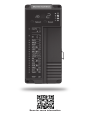
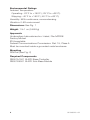
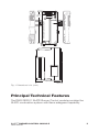
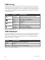
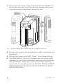
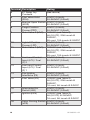
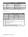
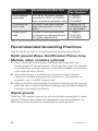
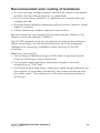
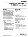
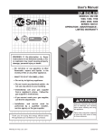
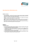
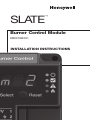
SLATE
™
Burner Control Module
R8001B2001
INSTALLATION INSTRUCTIONS
Scan for more information
Application
SLATE™ brings configurable safety and programmable logic
together into one single platform. The platform can easily be
customized for almost any requirement or application–offering
virtually limitless development opportunities with far less
complexity.
The R8001B2001 Burner Control module provides flame
safeguard controls for a variety of applications within the SLATE
system. It can be configured as a primary or programmer, semiautomatic or fully automatic.
Features
• Provides 24 VDC or 24 to 240 VAC flame safeguard
• Valve proving
• Parameters and behaviors that allow emulation of 7800 and
SOLA Series flame safeguards
• Dual fuels capability
• Configurable safety
• Safety relay
Specifications
Electrical Ratings:
Voltage and Frequency:
24 VDC (± 15%),
24 VAC (± 15%), 50/60 Hz,
85-264 VAC, 50/60 Hz
Maximum Total Connected Load: 2000 VA
Fusing Total Connected Load: 15A Fast Blow, type SC or
equivalent
SLATE™ BURNER CONTROL MODULE
R8001B2001
3
Environmental Ratings
Ambient Temperature:
Operating: -20°F to +150°F (-29°C to +66°C).
Shipping: -40°F to +150°F (-40°C to +66°C).
Humidity: 95% continuous, noncondensing.
Vibration: 0.5G environment
Dimensions:See Fig. 1
Weight:1 lb 1 oz (0.48 Kg)
Approvals
Underwriters Laboratories Inc. Listed, File: MP268
Factory Mutual
IRI Acceptable
Federal Communications Commission: Part 15, Class A
Must be mounted inside a grounded metal enclosure.
Mounting
DIN Rail (See Fig. 2)
Required Components
R8001A1001 SLATE Base Controller
R8001S9001 SLATE Sub-Base Module
432-00010—01
7-3/32
(181)
2-11/16 (68)
4-19/32 (117)
M35382
Fig. 1. Dimensions in in. (mm).
Principal Technical Features
The R8001B2001 SLATE Burner Control module provides the
SLATE combustion system with flame safeguard capability.
SLATE™ BURNER CONTROL MODULE
R8001B2001
5
LED Array
There are four LEDs on the front of the burner control module
that provide quick identification of system status and problems.
This status is broadcast to other modules on the platform bus in
case they are affected by the inoperable module(s). See Table 1
for descriptions.
LED
Color
Power No light
Green
CPU
Fault
Flame
Description
System does not have power
System has power
Red
No valid configuration
Green
Running
Red
Fault
No light
No fault
Yellow
Flame is detected
No light
No flame is detected
Table 1. LED Descriptions.
LED Displays
The SLATE system modules have three-character LED displays
used for indicating the module number of the SLATE system.
They also have three-position LED colors to indicate terminal
states as shown in Table 2.
Color
Description
Green
Terminal is ON or is Normal
Red
Fault
No light
Terminal is OFF or Not in use
Table 2. Terminal LED Meanings.
632-00010—01
Select and Reset Buttons
The SLATE Burner Control have Select and Reset buttons
located on the front of the module and beneath the segment
display. The Reset button is used to clear a lockout and reset the
module. The Select button is used to scroll through the segment
display information.
There are also 22 LEDs for each of the burner control module
terminals.
Installation
WARNING
Fire or Explosion Hazard
Can cause severe injury, death, or property damage.
Verification of safety requirements must be performed
each time a control is installed on a burner to prevent
possible hazardous burner operation.
When Installing This Product
1. Read these instructions carefully. Failure to follow them could
damage the product or cause a hazardous condition.
2. Check the ratings given in the instructions and on the product
to make sure the product is suitable for your application.
3. After installation is complete, check out the product operation
as provided in these instructions.
4. The SLATE module must be mounted in an electrical
enclosure with adequate clearance for servicing, installation
and removal of modules.
WARNING
Electrical Shock Hazard.
Can cause severe injury, death or equipment damage.
SLATE™ BURNER CONTROL MODULE
R8001B2001
7
1. Disconnect the power supply before beginning installation to
prevent electrical shock and equipment damage. More than
one power supply disconnect can be involved.
M35383
Fig. 2. Installing the Burner Control Module on the Sub-Base Module.
2. Wiring must comply with all applicable codes, ordinances and
regulations.
3. Wiring must comply with NEC Class 1 (Line Voltage) wiring.
4. The R8001B2001 should not interfere with the proper safety
operation of the controls, limits and interlocks it is monitoring.
After installation, check each control, limit and interlock to
ensure that it is operating properly. DO NOT PLACE JUMPER
WIRES ACROSS THE INSTALLATION CONTROLS, LIMITS
AND INTERLOCKS.
832-00010—01
IMPORTANT
1.This equipment generates, uses and can radiate radio
frequency energy and, if not installed and used in accordance
with these instructions, may cause interference for radio
communications. It has been tested and found to comply
with the limits of a Class A computing device of part 15
of FCC rules, which are designed to provide reasonable
protection against such interference when operated in a
commercial environment. Operation of this equipment in a
residential area may cause interference; in which case, the
user, at their own expense, may be required to take whatever
measures are required to correct this interference.
2.This digital apparatus does not exceed the Class A limits for
radio noise, set out in the Radio Interfeence Regulations of
the Canadian Department of Communications.
3.Cable shield must be terminated to ground at both ends. If
shielded cable is NOT used, use three-wire twisted cable.
Wiring
WARNING
Fire or Explosion Hazard
Can cause severe injury, death, or property damage.
Disconnect the power supply from the main disconnect before
beginning installation to prevent electrical shock and equipment
damage. More than one disconnect can be required.
Terminal Description
1
Unused (reserved for
future use)
2
Unused (reserved for
future use)
3
Unused
4
K1 Relay Dry
Contacts
(Burner / Fan Motor)
SLATE™ BURNER CONTROL MODULE
R8001B2001
Rating
------9.8 FLA, 58.8 LRA @ 120VAC,
4A (0.5 PF), 20A inrush @
240VAC
9
Terminal Description
5
K1 Relay Dry
Contacts
6
Pilot Valve Hold
(PVH)
7
Manual Open Switch
(MOS)
8
Purge Position
Proven (PPP)
9
Main Valve 2 (MV2)
10
11
12
13
14
15
16
17
18
Lightoff Position
Proven (LPP)
Main Valve 1 (MV1)
Limit and Control
Input (LCI) / Fuel
(F) 2
Limit and Control
Input (LCI) / Fuel
(F) 1
Pre-Ignition
Interlocks (PII)
Pilot Valve (PV)
Rating
(see above)
24VDC (0.5mA),
24-240VAC (0.2mA)
24VDC (0.5mA),
24-240VAC (0.2mA)
24VDC (0.5mA),
24-240VAC (0.2mA)
120VAC (see Table 2),
4A (0.5 PF), 20A inrush @
240VAC,
2A cont, 10A inrush @ 24VDC
24VDC (0.5mA),
24-240VAC (0.2mA)
120VAC (see Table 2),
4A (0.5 PF), 20A inrush @
240VAC,
2A cont, 10A inrush @ 24VDC
24VDC (0.5mA),
24-240VAC (0.2mA)
24VDC (0.5mA),
24-240VAC (0.2mA)
24VDC (0.5mA),
24-240VAC (0.2mA)
120VAC (see Table 2),
4A (0.5 PF), 20A inrush @
240VAC,
1A cont, 5A inrush @ 24VDC
Interrupted Air
24VDC (0.5mA),
Switch (IAS)
24-240VAC (0.2mA)
Ignition (IGN)
120VAC (see Table 2),
4A (0.2 PF) @ 240VAC,
1A cont, 5A inrush @ 24VDC
Valve Proving Switch 24VDC (0.5mA),
(VPS)
24-240VAC (0.2mA)
1032-00010—01
Terminal Description
19
Lockout Interlocks
(ILK)
20
Vref+
21
22
Rating
24VDC (0.5mA),
24-240VAC (0.2mA)
24VDC (0.1mA),
24VAC (0.1mA),
85-264VAC (0.2mA)
--(see Vref+ above)
Unused
Vref-
Note: only one voltage can be used per module (same at all
terminals).
Table 3. Terminal Ratings.
Combination Pilot Valve
1
C
2
B
3
E
4
D
5
D
Load Table Key
A
4.5 A Ignition
Ignition
no load
no load
A
A
A
MV1 & MV2
E
E
E
E
D
B
4.5 A plus 50 VA Pilot Duty
C
180 VA Ign plus motor valves with: 660 VA inrush, 360
VA open, 250 VA hold
D
2 A Pilot Duty
E
65 VA Pilot Duty plus motor valves with: 3850 VA
inrush, 700 VA open, 250 VA hold
Table 4. Combinations for PV, IGN, MV1 & MV2 Terminals.
SLATE™ BURNER CONTROL MODULE
R8001B2001
11
Application
Line voltage
terminals
Communication Lines
Other terminals
Recommended Wire Size
Recommended
Part Numbers
14, 16 or 18 AWG copper
TTW60C,
conductor, 600 volt insulaTHW75C,
tion, moisture-resistant wire. THHN90C
22 AWG two-wire twisted
Belden 8723
pair with ground, or fiveshielded cable
wire.
or equivalent.
18 AWG wire insulated for
TTW60C,
voltages and temperatures
THW75C,
for given application.
THHN90C
Table 5. Recommended Wire Sizes and Part Numbers.
Recommended Grounding Practices
Use an Earth ground or a signal ground as described below.
Earth ground (Base, Rectification Flame Amp
Module, other modules optional)
1. Use to provide a connection between the base and the
control panel of the equipment. Earth ground must be capable
of conducting enough current to blow the breaker in the event
of an internal short circuit.
2. Use wide straps or brackets to provide minimum length,
maximum surface area ground conductors. If a leadwire is
required, use 14 AWG copper wire.
3. Make sure that mechanically tightened joints along the ground
path are free of nonconductive coatings and protected against
corrosion on mating surfaces.
Signal ground
Note the 18V system ground is not electrically connected to earth
ground. Follow local codes and appliance recommendations to
determine if this should be connected to earth ground.
1232-00010—01
Recommended wire routing of leadwires
• Do not run high voltage ignition transformer wires in the same
conduit with the flame detector or data lines.
• Do not route flame detector or data lines in conduit with line
voltage circuits.
• Enclose flame detector leadwires without armor cable in metal
cable or conduit.
• Follow directions in flame detector instructions.
Be sure loads do not exceed the terminal ratings. Refer to the
labels or terminal ratings in Table 3.
The SLATE system must be mounted in an electrical enclosure.
When mounting in an electrical enclosure, provide adequate
clearance for servicing, installation and removal of SLATE
modules.
Maximum wire length:
• The maximum leadwire length is 300 feet to terminal inputs
(Control, Running/Lockout Interlock)
• For remote reset leadwires, maximum length to remote
pushbutton is 1000 feet.
• For Remote Bus data lines, maximum cable length depends on
the number of modules connected, the noise conditions and
the cable used. The maximum of all interconnecting wires is
4000 feet.
SLATE™ BURNER CONTROL MODULE
R8001B2001
13
1
BURNER CONTROL
MODULE
2
6 RELAYS
15 OPTO-INPUTS
UNUSED
3
4
5
BLR, HSI OR
WIRE SHEET
6 PVH
7 M05
8 PPP
9
MV2
10 LPP
11
MV1
12 LCI FUEL2
13 LCI FUEL1
14 PII
PV
15
16 IAS
IGN
17
18 VPS
SAFETY
RELAY
19
ILK
20
BIAS
REMOTE BUS IS
ON SUBBASE
21
VREF
22
M35387
Fig. 3. Wiring diagram for Burner Control Module.
1432-00010—01
SLATE™ BURNER CONTROL MODULE
R8001B2001
15
32-00010-01
For more information on the R8001B2001 and the entire SLATE
system please refer to the SLATE User Guide located on our website
at http://www.combustion.honeywell.com/SLATE
Automation and Control Solutions
Honeywell International Inc.
® U.S. Registered Trademark.
1985 Douglas Drive North
© 2015 Honeywell International Inc.
Golden Valley, MN 55422
32-00010—01 M.S. 05-15
customer.honeywell.com
Printed in U.S.A.