1
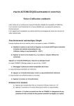
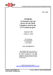
IS0306
rev. B ecn 9055 11/2013
MG3000 - Tachometer (NMEA2000 and J-1939)
TACH
1760
RPM
FUEL
Installation / User Manual
www.faria-instruments.com
IMPORTANT: This User’s Guide outlines the functionality and usage of the MG3000 tachometer.
stored onboard for reference at all times.
reference only. The continuing accuracy of this Guide cannot be guaranteed.
† NMEA 2000 is a regulated trademark of the National Marine Electronics Association or its
subsidiaries.
About This Guide
IMPORTANT: Read this User’s Guide carefully before using the MG3000 digital instrumentation.
Need Assistance?
IMPORTANT: This guide was written for the 4 inch MG3000 tachometer with the latest Software
version: referenced below. Gauges with other software versions may have features not documented
DATE
Rev.
03/15/2013
Pre
04/02/2013
Pre
A
DESCRIPTION
Preliminary release
Program Version
PGF399_B
PGF399_B3
Release of manual
PGF399_B3
NMEA 2000 - Warnings Disclaimer
addition to the standard Version 1.301 NMEA 2000 alarms. Consult engine manufacturer if you have
Index
Installation . .
Wiring Diagram
Power On . .
.
.
.
.
.
.
.
.
.
.
.
.
.
.
.
.
.
.
.
.
.
.
.
.
.
.
Offset Settings . . . . .
Engine Initialization . . .
.
.
.
.
.
.
.
.
.
.
.
.
.
.
.
.
.
.
.
.
.
.
.
.
.
.
.
.
.
.
.
.
.
.
.
.
.
.
.
.
.
.
.
.
.
. . . . .
Remaining Fuel Source
Number of Tanks . . .
. . .
. . .
Fuel Add To? . . . .
.
.
.
.
.
.
.
.
.
.
.
.
.
.
. . . . . . . . . .
. .
Reset Fuel Totalizer . . . . .
. . . . . . .
Contrast Settings . . . . .
Backlight Settings . . . . .
. . . . . .
. . . . . . . . .
. . . .
Adding Fuel to the Fuel Tank .
. . . . . . . . . .
.
.
.
.
.
.
.
.
.
.
.
.
.
.
.
.
.
.
.
.
.
.
.
.
.
.
.
.
.
.
.
.
.
.
.
.
.
.
.
.
.
.
.
.
.
.
.
.
.
.
. .
. .
. .
. .
. .
. .
. .
. .
. .
. .
. .
. .
. .
Edit Menu . . . . . . . . . . . . . .
. . . . . .
Initialization . . . . . . . . . . .
. . . . . . . .
Audio Settings . . . . . . . . .
Warning Audio Settings (On or Off)
Setting Saved Audio Setting . . .
Button Press Audio Setting . . .
All Sounds. . . . . . . . . .
Clock Settings. . . . . . . . . .
. . . .
Change Clock Time Offset . . .
Alarms . . . . . . . . . . . .
Viewing Current Alarms . . . .
Clear Alarms . . . . . . . . .
Set Units . . . . . . . . . . . .
Performing a Self Test . . . . . .
Software Version . . . . . . . .
Perform a Master Reset . . . . . .
. . . . . . .
. . . . . . . . .
. . . . .
Adding Fuel to the Tank . . . .
Setting the Tank Size . . . . .
Calibrating the Fuel Sender . . . .
.
.
.
.
.
.
.
.
.
.
.
.
.
.
.
.
.
.
.
.
.
.
.
.
.
.
.
.
.
.
.
.
.
.
.
.
.
.
.
.
.
.
.
.
.
.
.
.
.
.
.
.
.
.
.
.
.
.
.
.
.
.
.
.
.
.
.
.
.
.
.
.
.
.
.
.
.
.
.
.
.
.
.
.
.
.
.
.
.
.
.
.
.
.
.
.
.
.
.
.
.
.
.
.
.
.
.
.
.
.
.
.
.
.
.
.
.
.
.
.
.
.
.
.
.
.
.
.
.
.
.
.
.
.
.
.
.
.
.
.
.
.
.
.
.
.
.
.
.
.
.
.
.
.
.
.
.
.
.
.
.
.
.
.
.
.
.
.
.
.
.
.
.
.
.
.
.
.
.
.
.
.
.
.
.
.
.
.
.
.
.
.
.
.
.
.
.
.
.
.
.
.
.
.
.
.
.
.
.
.
.
.
.
.
.
.
.
.
.
.
.
.
.
.
.
.
.
.
.
.
.
.
.
.
.
.
.
.
.
.
.
.
.
.
.
.
.
.
.
.
.
.
.
.
.
.
.
.
.
.
.
.
.
.
.
.
.
.
.
.
.
.
.
.
.
.
.
.
.
.
.
.
.
.
.
.
.
.
.
.
.
.
.
.
.
.
.
.
.
.
.
.
.
.
.
.
.
.
.
.
.
.
.
.
.
.
.
.
.
.
.
.
.
.
.
.
.
.
.
.
.
.
.
.
.
.
.
.
.
.
.
.
.
.
.
.
.
.
.
.
.
.
.
.
.
.
.
.
.
.
.
.
.
.
.
.
.
.
.
.
.
.
.
.
.
.
.
.
.
.
.
.
.
.
.
.
.
.
.
.
.
.
.
.
.
.
.
.
.
.
.
.
.
.
.
.
.
.
.
.
.
.
.
.
.
.
.
.
.
.
.
.
.
.
.
.
.
.
.
.
.
.
.
.
.
.
.
.
.
.
.
.
.
.
.
.
.
.
.
.
.
.
.
.
.
.
.
.
.
.
.
.
.
.
.
.
.
.
.
.
.
.
.
.
.
.
.
.
.
.
.
.
.
.
.
.
.
.
.
.
.
.
.
.
.
.
.
.
.
.
.
.
.
.
.
.
.
.
.
.
.
.
.
.
.
.
.
.
.
.
.
.
.
.
.
.
.
.
.
.
.
.
.
.
.
.
.
.
.
.
.
.
.
.
.
.
.
.
.
.
.
.
.
.
.
.
.
.
.
.
.
.
.
.
.
.
.
.
.
.
.
.
.
.
.
.
.
.
.
.
.
.
.
.
.
.
.
.
.
.
.
.
.
.
.
.
.
.
.
.
.
.
.
.
.
.
.
.
.
.
.
.
.
.
.
.
.
.
.
.
.
.
.
.
.
.
.
.
.
.
.
.
.
.
.
.
.
.
.
.
.
.
.
.
.
.
.
.
.
.
.
.
.
.
.
.
.
.
.
.
.
.
.
.
.
.
.
.
.
.
.
.
.
.
.
.
.
.
.
.
.
.
.
.
.
.
.
.
.
.
.
.
.
.
.
.
.
.
.
.
.
.
.
.
.
.
.
.
.
.
.
.
.
.
.
.
.
.
.
.
.
.
.
.
.
.
.
.
.
.
.
.
.
.
.
.
.
.
.
.
.
.
.
.
.
.
.
.
.
.
.
.
.
.
.
.
.
.
.
.
.
.
.
.
.
.
.
.
.
.
.
.
.
.
.
.
.
.
.
.
.
.
.
.
.
.
.
.
.
.
.
.
.
.
.
.
.
.
.
.
.
.
.
.
.
.
.
.
.
.
.
.
.
.
.
.
.
.
.
.
.
.
.
.
.
.
.
.
.
.
.
.
.
.
.
.
.
.
.
.
.
.
.
.
.
.
.
.
.
.
.
.
.
.
.
.
.
.
.
.
.
.
.
.
.
.
.
.
.
.
.
.
.
.
.
.
.
.
.
.
.
.
.
.
.
.
.
.
.
.
.
.
.
.
.
.
.
.
.
.
.
.
.
.
.
.
.
.
.
.
.
.
.
.
.
.
.
.
.
.
.
.
.
.
.
.
.
.
.
.
.
.
.
.
.
.
.
.
.
.
.
.
.
.
.
.
.
.
.
.
.
.
.
.
.
.
.
.
.
.
.
.
.
.
.
.
.
.
.
.
.
.
.
.
.
.
.
.
.
.
.
.
.
.
.
.
.
.
.
.
.
.
.
.
.
.
.
.
.
.
.
.
.
.
.
.
.
.
.
.
.
.
.
.
.
.
.
.
.
.
.
.
.
.
.1
.2
.2
.3
.3
.3
.3
.4
.4
.4
.4
.5
.5
.5
.5
.
.
.
.7
.7
.8
.8
.8
.8
.9
.9
10
10
10
11
11
11
12
12
12
12
13
13
13
14
14
14
14
14
15
15
17
17
17
17
18
18
. . . . . .
Fuel Totalizer . . . . . . . . . . . .
Reset the Fuel Totalizer . . . . . .
. . . . . . . . .
. . . . . . . . .
. . . . . . .
. . . . . . . .
Setting the Number of Data Pages . . . .
. . . . . . . . . . . .
. . . . . . . .
Data Page Auto Scrolling Setting . . . .
Change the Auto Scrolling Interval Time
. . . . . . . . . . . . .
. . . . . . . . .
Tanks . . . . . . . . . . . . . . .
Engine . . . . . . . . . . . . . .
Engine Maintenance Interval . . . .
Reset the Maintenance Interval . . .
. . . . . . . . .
Trim . . . . . . . . . . . . . . .
Calibrating Trim Sender . . . . . .
Battery . . . . . . . . . . . . . .
Oil Pressure . . . . . . . . . . . .
. . . . . . . . . . . .
. . . . . . . . . . . . . .
. . . . . . . . . . . . . . .
Steer Angle . . . . . . . . . . . . .
. . . . . . .
. . . . . .
. . .
. . . . . .
Set Custom Alerts . . . . . . . . . .
Trouble Shooting . . . . . . . . . . . .
Engine Warnings . . . . . . . . . .
Network Trouble shooting Chart . . . . . .
Abbreviations Used - Tachometer . . . . .
. . . . . . . . . . . .
Warning Buzzer . . . . . . . . . . . .
.
.
.
.
.
.
.
.
.
.
.
.
.
.
.
.
.
.
.
.
.
.
.
.
.
.
.
.
.
.
.
.
.
.
.
.
.
.
.
.
.
.
.
.
.
.
.
.
.
.
.
.
.
.
.
.
.
.
.
.
.
.
.
.
.
.
.
.
.
.
.
.
.
.
.
.
.
.
.
.
.
.
.
.
.
.
.
.
.
.
.
.
.
.
.
.
.
.
.
.
.
.
.
.
.
.
.
.
.
.
.
.
.
.
.
.
.
.
.
.
.
.
.
.
.
.
.
.
.
.
.
.
.
.
.
.
.
.
.
.
.
.
.
.
.
.
.
.
.
.
.
.
.
.
.
.
.
.
.
.
.
.
.
.
.
.
.
.
.
.
.
.
.
.
.
.
.
.
.
.
.
.
.
.
.
.
.
.
.
.
.
.
.
.
.
.
.
.
.
.
.
.
.
.
.
.
.
.
.
.
.
.
.
.
.
.
.
.
.
.
.
.
.
.
.
.
.
.
.
.
.
.
.
.
.
.
.
.
.
.
.
.
.
.
.
.
.
.
.
.
.
.
.
.
.
.
.
.
.
.
.
.
.
.
.
.
.
.
.
.
.
.
.
.
.
.
.
.
.
.
.
.
.
.
.
.
.
.
.
.
.
.
.
.
.
.
.
.
.
.
.
.
.
.
.
.
.
.
.
.
.
.
.
.
.
.
.
.
.
.
.
.
.
.
.
.
.
.
.
.
.
.
.
.
.
.
.
.
.
.
.
.
.
.
.
.
.
.
.
.
.
.
.
.
.
.
.
.
.
.
.
.
.
.
.
.
.
.
.
.
.
.
.
.
.
.
.
.
.
.
.
.
.
.
.
.
.
.
.
.
.
.
.
.
.
.
.
.
.
.
.
.
.
.
.
.
.
.
.
.
.
.
.
.
.
.
.
.
.
.
.
.
.
.
.
.
.
.
.
.
.
.
.
.
.
.
.
.
.
.
.
.
.
.
.
.
.
.
.
.
.
.
.
.
.
.
.
.
.
.
.
.
.
.
.
.
.
.
.
.
.
.
.
.
.
.
.
.
.
.
.
.
.
.
.
.
.
.
.
.
.
.
.
.
.
.
.
.
.
.
.
.
.
.
.
.
.
.
.
.
.
.
.
.
.
.
.
.
.
.
.
.
.
.
.
.
.
.
.
.
.
.
.
.
.
.
.
.
.
.
.
.
.
.
.
.
.
.
.
.
.
.
.
.
.
.
.
.
.
.
.
.
.
.
.
.
.
.
.
.
.
.
.
.
.
.
.
.
.
.
.
.
.
.
.
.
.
.
.
.
.
.
.
.
.
.
.
.
.
.
.
.
.
.
.
.
.
.
.
.
.
.
.
.
.
.
.
.
.
.
.
.
.
.
.
.
.
.
.
.
.
.
.
.
.
.
.
.
.
.
.
.
.
.
.
.
18
19
19
20
20
20
21
21
21
22
22
22
23
24
24
24
25
25
25
27
27
27
28
28
29
29
29
29
30
31
31
32
33
34
34
Installation
Description
greater than one second makes a selection.
TACH
1760 RPM
FUEL
1
Panel Thickness
Hole Sizes
Attaching The Back Clamp
Page 1
3
2
1.
DOWN button
2.
MODE button
3.
UP button
MG3000 Wiring Diagram
Speedometer
Tachometer
6
5
4
3
2
1
6
5
4
6
5
4
3
2
1
6
5
4
12- pin connector
7
8
9
11
10
12
1
2
3
7
8
9
11
10
12
1
2
3
12- pin connector
Pitot
connection
%-/ .$$#
Pin 1
Pin 2
Pin 3
Pin 4
Pin 5
Pin 6
Pin 7
Pin 8
Pin 9
Pin 10
Pin 11
Pin 12
Pin 1
Pin 2
Pin 3
Pin 4
Pin 5
Pin 6
Pin 7
Pin 8
Pin 9
7.7 vDC (Faria Bus +)
Faria Bus A
Faria Bus B
Ground
12vDC Ignition
Analog Input 1
Analog Input 2
Analog Input 3
5 B+
5
3&,(1(-,)2+.$/1-.(,
Pin 10 5 Ground
5 '($*#
Pin 11 5(
5(
Pin 12 5-4
5-4
Multifunction Gauge
N/C
N/C
NMEA 0183 (+)
NMEA 0183 (-)
N/C
N/C
&,(1(-,2+.$/
Ignition
Analog Input 1
Analog Input 2
Analog Input 3
Pin 1
Pin 2
Pin 3
Pin 4
Pin 5
Pin 6
Ignition
Jumper required for the J1939
harness and is Not required
for the NMEA2000 harnesses.
6- pin connector (GPS)
7.7 vDC (Faria Bus +)
Faria Bus A
Faria Bus B
Ground
12 vDC Ignition
C
C
C
7.7 vDC (Faria Bus +)
Faria Bus A
Faria Bus B
Ground
6- pin connector (Depth)
Pin 1
Pin 2
Pin 3
Pin 4
Pin 5
Pin 6
N/C
N/C
Depth Signal (+)
Depth Signal (-)
N/C
N/C
Information from the ECU
Wire Jacket
4- pin connector
4- pin connector
Pin A
Pin B
Pin C
Pin D
8.4 vDC Faria Bus (+)
Faria Bus A
Faria Bus B
Ground
Faria Bus
Pin A
Pin B
Pin C
Pin D
8.4 vDC Faria Bus (+)
Faria Bus A
Faria Bus B
Ground
Faria Bus
(To other gauges)
Page 2
Power On
SELF TEST
SOFTWRE REV.
PGFXXX_XX
Settings on
System Setup (Tachometer)
Select System Language
1) Use the UP or DOWN buttons to select the desired language to be used. The
Clock Offset Settings
time zone offset for the Clock to show the correct time.
13.
Engine Initialization
1) Use the UP or DOWN buttons to select the number of engines installed on the
Page 3
SET ENGINE ID
PORT
MID PORT
STARBOARD
Set Engine Manufacturer Type
Set the engine manufacturer in the ENGINE TYPE menu. If you are using Yamaha,
ENGINE
TYPE
RESET INTRVL
MAINT INTRVL
TYPE
NMEA STD
YAMAHA
HONDA
Default Display Units
Tank Setup
Important:
than one MG3000 tachometer is in use.
Remaining Fuel Source
Note: The Remaining Fuel Source is the source for the remaining fuel in the system.
This value is used to calculate various Fuel Economy functions in the MG3000. Fuel
REMAINING
FUEL SOURCE
FUEL LEVEL
ENG FUEL RATE
Page 4
Number of Tanks
1) Use the UP or DOWN buttons indicate the number of fuel tanks in the system.
2) Press and hold the MODE button to save the selected number of fuel tanks.
Set Type of Tank
TYPE.
2) Press and hold the MODE button to save the selection.
Note:
SET TANK #
TYPE
FUEL
FRESH WATER
Fuel Tank Setup
SET FUEL
T1: FUEL
50.0 GAL
PRESS OR
Page 5
Normal Mode - Default Pages and Display Settings
RPM
3000 RPM
T1: FUEL
50 GAL
ENGINE HRS
6249.3 HR
TRIM
TRIP A HOURS
100.2 HRS
FUEL INST
CLOCK
COG
BATTERY 1
13.6 V
ENGINE TEMP
136 ˚F
12:00 AM
T1: FUEL
20.1 GPH
259 ˚TRUE
OIL PRESS
80.7 PSI
Menu Options
RESET TOTALIZER: Resets the total fuel used.
TRIP DATA
FUEL LEVEL
EDIT MENU: is used to make global Tachometer settings changes.
CONTRAST:
LIGHTING: is used to adjust the lighting level(s).
DEPTH
Note:
User manual.
Enter the Menu Options page.
LIGHTING
Note:
INSTRUMENT.
To reset the Totalizer Fuel Used:
Reset Fuel Totalizer
The Fuel Totalizer is used when more than one Fuel Tank is installed in the system.
The Totalizer will monitor all of the installed Fuel Tanks, gather the data and combine for
reset.
this time for all engines combined into one amount.
Warning: Resetting the totalizer will also reset all collected Fuel economy data.
To reset the Fuel Totalizer:
reset the totalizer fuel used, or select NO to exit.
HOLD MODE
TO ENTER
RESET TOTALIZR
TRIP DATA
TOTALIZER
RESET?
NO
YES
Display Settings
3) Press and hold MODE to make the selection.
Backlight Settings.
Page 7
HOLD MODE
TO ENTER
CONTRAST
RESET TOTLIZR
Contrast Settings
4) Press the UP button to increase or the DOWN button to decrease the contrast
5) The contrast setting is automatically saved to the tachometer and synchronized to
all gauges linked to the MG3000
ADJUST
LCD
CONTRAST
PRESS OR
ADJUST
LCD
CONTRAST
PRESS OR
Backlight Settings
By default the Dial Backlight (all gauges connected to the MG3000 tachometer) and
brighter or dimmer at the same time. Use the MG3000 tachometer to adjust the lighting
2) Press and hold the MODE button to make the selection.
3) Use the UP or DOWN button to select the lighting level to adjust.
lighting and the System lighting, which will adjust all instruments connected to the
tachometer.
4) Press and hold the MODE button to make the selection.
dim the lighting intensity.
HOLD MODE
TO ENTER
LIGHTING
CONTRAST
LIGHTING
ADJUST LCD
ADJUST DIAL
ADJUST SYSTEM
ADJUST DIAL
BRIGHTNESS
100 %
PRESS OR
Fuel Level
HOLD MODE
TO ENTER
FUEL LEVEL
EDIT MENU
2) Press and hold the MODE button to make the selection.
3) Use the UP or DOWN buttons to select the fuel tank to make an adjustment to.
4) Press and hold the MODE button to enter the selection.
SELCT TANK TO
ADD FUEL TO ?
T1: FUEL
T2: FUEL
Page 8
Setting The Fuel Level
if more than one MG3000 tachometer is in use. To set the fuel level to full:
3) Press and hold the MODE button to make selection.
SELCT TANK TO
ADD FUEL TO
T#:FUEL
T#:FUEL
T#: FUEL#
SET FULL
ADD FUEL
4) Use the UP or DOWN buttons to select which tank to add fuel to.
5) Press and hold the MODE button to make selection.
SET TANK FULL
NO
YES
Note:
number to calculate the Fuel economy calculations. An inaccuracy in this number will
result in faulty calculations.
9) Use the MODE button to make the selection.
Adding Fuel to the Fuel Tank:
T#: FUEL#
ADD FUEL
SET FULL
3) Press and hold the MODE button to make selection.
4) Use the UP or DOWN buttons to select which tank to add fuel to.
5) Press and hold the MODE button to make selection.
8) Use the UP or DOWN buttons to set the volume of Fuel that has been added to
the fuel tank.
Note:
Page 9
T#: FUEL#
0.0 GAL
Trip Data
HOLD MODE
TO ENTER
TRIP DATA
FUEL LEVEL
2) Use the UP or DOWN buttons to select TRIP DATA.
3) Press and hold the MODE button to make selection.
View Trip and Season Data
1) Use the UP or DOWN buttons to select TRIP A, TRIP B or SEASON.
2) Press and hold the MODE button to enter the selection.
3) Use the UP or DOWN buttons to select VIEW DATA.
ENGINE HOURS
4.7
FUEL USED
32.8 GAL
4) Press and hold the MODE button to make a selection.
5) Use the UP or DOWN buttons to select information to be shown.
Note
Resetting Trip and Season Data
1) Use the UP or DOWN buttons to select TRIP A, TRIP B, or SEASON.
2) Press and hold the MODE button to enter the selection.
3) Use the UP or DOWN buttons to select RESET DATA.
4)
TRIP A
RESET?
NO
YES
Press and hold the MODE button.
5) Use the UP or DOWN buttons to select YES to reset the data, or select NO to exit.
Page 10
Edit Menu
Scroll until EDIT MENU is highlighted, then hold the MODE button to enter.
Test or Master Reset and view the Software version.
LIGHTING
as adjust lighting and contrast.
in a monitored data value.
Note:
architecture individual functions may not be available for your installation. Check with
your engine and boat manufacturer for function availability.
System
Use the SYSTEM edit menu to initialize the tachometer, set the system language,
software version for the tachometer. The SYSTEM edit menu is used for entering
EDIT MENU
SYSTEM
CAL TRIM
FUEL SETUP
2) Use the UP and/or DOWN buttons to select EDIT MENU.
4) Use the UP and/or DOWN buttons to select SYSTEM.
5) Press and hold the MODE button to make the selection.
Initialization
2) Press and hold the MODE button to make selection.
3) Use the UP or DOWN buttons to select YES to initialize or NO to return to the
Page 11
ENTER
INITIALIZATION
YES
NO
EDIT menu.
4) Press and hold the MODE button to make selection.
System Language
2) Press and hold the MODE button to make the selection.
3) Use the UP or DOWN buttons to select the desired language to be used. The
Audio Settings
The Audio menu is used to turn on or off the buzzer for warnings. To make changes to
Note:
SYSTEM INFO
AUDIO
CLOCK SETTING
SET UNITS
2) Press and hold the MODE button to make the selection.
3) Use the UP or DOWN buttons to select the desired menu.
4) Press and hold the MODE button to make the selection.
Warning Audio Setting (ON or OFF)
Use WARNING BEEP to turn the buzzer ON or OFF while a warning is occurring in the
AUDIO SETTING
WARNING BEEP
SETTING SAVED
BUTTON PRESS
AUDIO menu:
IMPORTANT: Turning off the WARNING BEEP is NOT recommended.
1) Use the UP or DOWN buttons to select the WARNING BEEP.
2) Press and hold the MODE button to enter the selection.
WARNING BEEP
AUDIO STATUS
ON
OFF
AUDIO SETTING
SET SAVED
BUTTON PRESS
ALL
Page 12
Setting Saved Audio Setting
Use SET SAVED to turn the buzzer ON or OFF after a setting is saved in the tachometer.
1) Use the UP or DOWN buttons to select the SET SAVED.
2) Press and hold the MODE button to enter the selection.
SETTING SAVED
AUDIO STATUS
ON
OFF
Button Press Audio Setting
tachometer.
1) Use the UP or DOWN buttons to select the BUTTON PRESS.
2) Press and hold the MODE button to enter the selection.
AUDIO SETTING
BUTTON PRESS
ALL
WARNING BEEP
BUTTON PRESS
AUDIO STATUS
ON
OFF
All Sounds
Note: The audio setting ALL, should NOT be used to turn OFF warnings.
2) Press and hold the MODE button to enter the selection.
Clock Settings
You will be asked to select the current time zone offset for the Clock to show the correct
The Clock data
. Clock data can be shown
using a 12 or 24 hour format.
Page 13
AUDIO SETTING
ALL
WARNING BEEP
SET SAVED
ALL BEEPS
AUDIO STATUS
ON
OFF
2) Press and hold the MODE button to enter the selection.
SYSTEM INFO
CLOCK SETTING
SET UNITS
SELF-TEST
To change the Clock Data Type:
3) Use the UP and/or DOWN buttons to select TYPE.
4) Press and hold the MODE button to enter the selection.
To change the time offset:
1) Use the UP and/or DOWN buttons to select TIME OFFSET.
2) Press and hold the MODE button to enter the selection.
3) Use the UP or DOWN button to select the correct TIME OFFSET value.
Alarms
Viewing Current Alarms
2) Press and hold the MODE button to enter the selection.
3) Use the UP or DOWN buttons to highlight VIEW.
4) Press and hold the MODE button to make the selection.
ALARMS
VIEW
CLEAR
CHECK
ENGINE
ACTIVE
06/10/09
Note: Date information is only available if a NMEA GPS antenna is in the system.
Clear Alarms
Warning: This will clear all recorded alarms the MG3000 has recorded and this action
ALARMS
CLEAR
VIEW
Page 14
CAN NOT BE UNDONE. It is best to leave this action to a trained service technician.
2) Press and hold the MODE button to enter the selection.
4) Press and hold the MODE button to make the selection.
5) Use the UP or DOWN buttons to select YES.
Set Units
Use the Set Units menu to change the units for the data recorded in the MG3000
tachometer. Use the Set Units menu to change the units on all data or individual
SYSTEM INFO
SET UNITS
SELF TEST
ALARMS
1) Use the UP or DOWN buttons to select SET UNITS.
4) Press and hold the MODE button to enter the selection.
Data
Units Available
All Units
US
Volume
Gal
Distance
Mile
EURO
Nautical Mile
Fahrenheit
Celsius
Feet
Meter
Fathom
kPA
Pressure
PSI
BAR
GPS COG
True
Magnetic
Flow Rate
Performing A Self Test
11) then:
Page 15
SYSTEM INFO
SELF-TEST
ALARMS
MASTER RESET
3) Use the UP or DOWN buttons to select YES.
SELF TEST
SOFTWRE REV.
PGFXXX_XX
Software Version
SYSTEM INFO
1) Use the UP or DOWN buttons to select SOFTWARE.
Performing A Master Reset
The Master Reset feature is used to reset the tachometer to the factory default settings.
1) Use the UP or DOWN buttons to select MASTER RESET.
2) Press and hold the MODE button to enter the selection.
SOFTWARE
PGFXXX
REV: X##
05/14/2012
SYSTEM INFO
MASTER RESET
SOFTWARE
INITIALIZE
MASTER RSET?
to select YES or NO.
If NO is selected the gauge will exit to the SYSTEM menu. If YES is selected continue
4) Use the UP or DOWN buttons to select YES or NO.
5) Press and hold the MODE button to enter the selection.
If NO is selected, the gauge will exit to the SYSTEM menu.
If YES is selected, the MG3000 tachometer will be reset to factory default settings.
CONTINUE WITH
MASTER RSET?
NO
YES
Fuel Set Up
used, set the tank size, select the fuel sender, calibrate the fuel sender, set the low fuel
warning and select the fuel remaining source for each tank. The Totalizer settings are
used to reset Totalizer fuel data and to set the Totalizer low fuel warning.
2) Use the UP or DOWN buttons to select EDIT MENU.
3) Press and hold the MODE button to enter the selection.
5) Press and hold the MODE button to enter the selection.
MAX SPEED
DISPLAY
Fuel Tank Setup
sender, set the low fuel warning, add fuel, reset fuel used, and select fuel remaining
source for each fuel tank.
1) Use the UP or DOWN buttons to select the fuel tank you wish to make adjustment
to.
2) Press and hold the MODE button to enter the selection.
FUEL SETUP
T:1 FUEL1
T:2 FUEL2
Setting The Fuel Level
if more than one MG3000 tachometer is in use. To set the fuel level to full enter the
4) Use the MODE button to make the selection.
T#: FUEL#
SET FULL
ADD FUEL
SET TANK FULL
NO
YES
Adding Fuel to the Fuel Tank:
T#: FUEL#
ADD FUEL
SET FULL
3) Use the UP or DOWN buttons to set the volume of Fuel that has been added to
Page 17
the fuel tank.
Note:
T#: FUEL#
0.0 GAL
Setting The Tank Size
SET FUEL
T:# FUEL#
0
GAL
PRESS OR
Note:
Calibrating The Fuel Sender
2) Press and hold the MODE button to enter the selection.
method.
Low Fuel Warning Level
select a tank then:
2) Press and hold the MODE button to enter the selection.
3) Use the UP button to increase or the DOWN button decrease the low fuel warning
level.
T#: FUEL#
LOW WARNING
FUEL LEVEL
TANK SIZE
LOW FUEL
WARNING
0.0 GAL
Page 18
Note:
Fuel Totalizer
The Fuel Totalizer is used when more than one Fuel Tank is installed in the system.
The Totalizer will monitor all the installed Fuel Tanks, gather the data and combine for
last reset.
this time for all engines combined into one amount.
To reset the Totalizer Fuel Used:
Warning: Resetting the totalizer will also reset all collected Fuel economy data.
To reset the Fuel Totalizer:
HOLD MODE
TO ENTER
RESET TOTALIZR
TRIP DATA
TOTALIZER
YES to reset the totalizer fuel used, or select NO to exit.
Page 19
Max Speed
2) Press and hold the MODE button to enter the selection.
View Max Speed
1) Use the UP or DOWN buttons to select VIEW.
2) Press and hold the MODE button to enter the selection.
Note
Resetting Max Speed
EDIT MENU
MAX SPEED
DISPLAY
DATA SOURCES
MAX SPEED
VIEW
RESET
MAX SPEED
57.4 MPH
1) Use the UP or DOWN buttons to select RESET.
2) Press and hold the MODE button to enter the selection.
MAX SPEED
RESET
VIEW
Page 20
Display Settings
2) Use the UP and/or DOWN buttons to select the EDIT MENU.
3) Press and hold the MODE button to enter the selection.
EDIT MENU
DISPLAY
DATA SOURCES
CSTM ALARMS
5) Press and hold the MODE button to enter the selection.
Setting the Number of Data Pages
2) Press and hold the MODE button to enter the selection.
SCREEN SETUP
LINE 2 DATA
3) Use the UP button to increase or the DOWN button to decrease the number of
Screen Setup
Mode. See DEFAULT PAGES AND DISPLAY SETTINGS
1) Use the UP and/or DOWN buttons to select SCREEN SETUP.
2) Press and hold the MODE button to enter the selection.
SCREEN SETUP
LINE 2 DATA
AUTO SCROLL
SCREEN #
TO SET UP
1
PRESS OR
SCREEN #
BATTERY 1
0.0 V
PRESS OR
Page 21
Setting the Line 2 Data
LINE 2 DATA
AUTO SCROLL
LCD COLOR
2) Press and hold the MODE button to enter the selection.
3) Use the UP or DOWN button to select the data you wish to see in the line 2
Note:
Water and OFF.
LINE 2 DATA
FUEL LEVEL
TRIM
WATER LEVEL
Data Page Auto Scroll Setting
AUTO SCROLL
LCD COLOR
# OF SCREENS
2) Press and hold the MODE button to enter the selection.
3) Use the UP or DOWN button to select STATUS.
5) Use the UP or DOWN buttons to select ON or OFF.
To change the Auto Scroll interval Time:
1) Use the UP or DOWN buttons to select TIME.
2) Press and hold the MODE button to enter the selection.
3) Use the UP button to increase or the DOWN button to decrease the interval.
4)
Press and hold the MODE button to enter the selection.
seconds.
Page 22
LCD Color (Not available with all MG3000 packages)
then:
LCD COLOR
# OF SCREENS
SCREEN SETUP
2) Press and hold the MODE button to enter the selection.
3) Use the UP or DOWN buttons to select the desired color.
Note:
4) Press and hold the MODE button to save selection.
Page 23
CHOOSE LCD
COLOR
WHITE
YELLOW
Data Sources
Use DATA SOURCES to set the engine instance and to set or reset the maintenance
Ballast, Bait Well, Rudder, Fresh Water, Gray Water or Black Water.
Refer to your manufacturers Gauge Installation Guide of installation instructions for
2) Use the UP and/or DOWN buttons to select EDIT MENU.
3) Press and hold the MODE button to enter the selection.
4) Use the UP or DOWN buttons to select DATA SOURCES .
CSTM ALARMS
POP UP ALERTS
5) Press and hold the MODE button to enter the selection.
Tanks
The Tanks data source is where the source of the information that is received from a
analog (US 240-33, EU 10-180 Fuel Senders), or digital sources (Bus Data). To make
2) Press and hold the MODE button to enter the selection.
DATA SOURCES
TANKS
ENGINE
SPEED SOURCE
TANK SOURCE
T1: XXXXX
T2: XXXXX
T1: XXXX2
4) Press and hold the MODE button to enter the selection.
TANK 1 SOURCE
US 240-33
EU 10-180
BUS DATA - 0
Note:
Engine
The Engine Data Source was set during initialization. If there is a need to change the
1) Use the UP and/or DOWN buttons to select ENGINE.
2) Press and hold the MODE button to enter the selection.
3) Use the UP or DOWN buttons to select ENGINE ID .
SPEED SOURCE
STEERING ANGLE
4) Press and hold the MODE button to enter the selection.
Page 24
5) Use the UP or DOWN buttons to select Engine ID.
Note:
SET ENGINE ID
PORT
MID PORT
MID STARBOARD
Engine Maintenance Interval
1) Use the UP and/or DOWN buttons to select ENGINE.
2) Press and hold the MODE button to enter the selection.
4) Press and hold the MODE button to enter the selection.
5) Use the UP button to increase, or the DOWN button to decrease the Maintenance
Interval.
ENGINE
MAINT INTRVL
ENGINE ID
VIEW ENG TYPE
SELECT MAINT
INTERVAL
0 HRS
PRESS OR
Note:
Reset the Maintenance Interval:
1) Use the UP and/or DOWN buttons to select ENGINE.
3) Press and hold the MODE button to enter the selection.
5) Press and hold the MODE button.
RESET MAINT
INTERVAL ?
Set Engine Manufacturer Type
1) Use the UP and/or DOWN buttons to select ENGINE.
2) Press and hold the MODE button to enter the selection.
3) Use the UP or DOWN buttons to select TYPE.
4) Press and hold the MODE button to enter the selection.
Page 25
ENGINE
TYPE
RESET INTRVL
MAINT INTRVL
TYPE
NMEA STD
YAMAHA
HONDA
Set Engine ID
1) Use the UP and/or DOWN buttons to select ENGINE.
2) Press and hold the MODE button to enter the selection.
3) Use the UP or DOWN buttons to select ENGINE ID.
4) Press and hold the MODE button to enter the selection.
SET ENGINE ID
PORT
MID PORT
STARBOARD
of the engine.
Trim
is set to NMEA 2000. To change the trim sender setting, enter the DATA SOURCES
1) Use the UP and/or DOWN buttons to select TRIM.
3) Press and hold the MODE button to enter the selection.
5) Press and hold the MODE button to enter the selection.
Calibrating Trim Sender
Use the MG3000 tachometer to calibrate the trim sender. To calibrate the trim sender,
1) Use the UP and/or DOWN buttons to select TRIM.
2) Press and hold the MODE button to enter the selection.
4) Press and hold the MODE button to enter calibration.
DOWN.
SELECT SENDER
9) The Trim Sender is now calibrated.
Battery
Use the Battery Data Source to determine the number of the batteries that are installed
in the system. By default the battery instance matches the engine ID. The number of
batteries is set to the number of engines selected during initialization. To change the
1) Use the UP and/or DOWN buttons to select BATTERY.
2) Press and hold the MODE button to enter the selection.
SELECT BATTERY
NUMBER
1
PRESS OR
3) Use the UP or DOWN buttons to select the number of batteries.
Oil Pressure
OIL PRESSURE
ANALOG
BUS DATA
2) Press and hold the MODE button to enter the selection.
used in the system.
Note:
Water Temp
WATER TEMP
ANALOG
BUS DATA
1) Use the UP and/or DOWN buttons to select WATER TEMP.
2) Press and hold the MODE button to enter the selection.
used in the system.
Page 27
Note
Air Temp
AIR TEMP
ANALOG
BUS DATA
1) Use the UP and/or DOWN buttons to select AIR TEMP.
2) Press and hold the MODE button to enter the selection.
in the system.
Note:
Speed
1) Use the UP and/or DOWN buttons to select SPEED SOURCE.
2) Press and hold the MODE button to enter the selection.
SPEED SOURCE
PADDLE WHEEL
PITOT
GPS
Steering Angle
STEERING ANGLE
NORMAL
INVERTED
2) Press and hold the MODE button to enter the selection.
3) Use the UP or DOWN buttons to select how the steering angle is used in the
system.
Page 28
Pop Up Alerts
ECONOMY, DURATION, EST RANGE and SPEED.
EDIT MENU
POP UP ALERTS
SYSTEM
FUEL SETUP
2) Use the UP or DOWN buttons to select the EDIT MENU.
3) Press and hold the MODE button to enter the selection.
5) Press and hold the MODE button to enter the selection.
FUEL ECON
To turn a POP UP alert ON or OFF
1) Use the UP or DOWN buttons to select the POP UP alert you wish to use.
2) Press and hold the MODE button to make the selection.
3) Use the UP or DOWN buttons to select STATUS.
4) Press and hold the MODE button to enter the selection.
5) Use the UP or DOWN button to select ON or OFF.
To set the POP UP threshold value:
The POP UP threshold value is the value that will trigger a POP UP alert to activate.
2) Press and hold the MODE button to enter the selection.
Setting the Pop Up Duration
1) Use the UP or DOWN buttons to select DURATION.
2) Press and hold the MODE button to enter the selection.
Page 29
RPM
TRIM CHANGE
Setting Custom Alarms
POP UP ALERTS
CSTM ALARMS
POP UP ALERTS
SYSTEM
OIL PRESSURE
TEMPERATURE
3) Press and hold the MODE button to make selection.
below.
To turn a Custom Alarm alert ON or OFF
1) Use the UP or DOWN buttons to select STATUS.
2) Press and hold the MODE button to enter the selection.
3) Use the UP or DOWN button to select ON or OFF.
OIL PRESSURE
STATUS
VALUE
OIL PRES STAT
ON
OFF
4) Press and hold the MODE button to save the selection.
To set the Custom Alarm threshold value:
alert to activate.
2) Press and hold the MODE button to enter the selection.
4) Press and hold the MODE button to save the setting.
OIL PRESSURE
VALUE
STATUS
SET ALARM
OIL PRES VALUE
80 PSI
PRESS OR
Page 30
Troubleshooting
receiving the data signal from one or more devices.
Note:
OFF and back ON to reset the gauge(s).
Engine Warnings
the outboard
Engine Warning
Engine TPS Fault
Possible Cause
Procedure
Critical
detected.
Critical
Seek assistance to
return to a safe harbor
immediately and see
your dealer.
Critical
Critical
Critical
Critical
Critical
Critical
Slow the engine down.
Critical
a critical engine condition occurs, or when a
Water in Fuel
System Charge Indicator
See your dealer as soon
Warning
Water in Fuel
See your dealer.
Warning
Engine Oil level is below normal.
See your dealer.
Warning
See your dealer.
Warning
See your dealer.
Warning
Engine Charging Potential is below normal.
See your dealer.
Warning
Battery Potential is below normal.
See your dealer.
Warning
See your dealer.
Other Engine Warnings
Warning
Page 31
Battery Potential is higher than normal.
See your dealer.
Warning
See your dealer.
Warning
See your dealer.
Warning
See your dealer.
Engine Warning
Possible Cause
Warning
Water Flow is below normal.
Procedure
See your dealer.
Network Troubleshooting Chart
Observation
Possible Cause
Procedure
source.
switched B+ from the ignition harness. See Note
below.
Network current draw is exceeding 3A.
Check all connections and wiring. Disconnect
accessory connections to network. Isolate
Check that the device is installed and connected
to the network.
analog sender.
Note:
Observation
Possible Cause
Procedure
converter.
Check the connection for the block-mounted
connected to the engine EMM.
Check for a minimum 11.5 V across the terminals
One or more terminators are missing from the
NMEA 2000 network.
Check for installation of two terminators on the
NMEA 2000 network. Check network bus cable
and device connections.
defaults.
running. Check ignition and ground connections
Page 32
Abbreviations Used - Tachometer
Abbreviation
Function
Abbreviation
RPM
Function
Total Fuel Used
Oil Pressure
Total Fuel Remaining
Total Instantaneous Fuel Flow
Total Average Fuel Flow
PORT TEMP
Fuel Economy
TRANS GEAR
Gear Position
GPS SPEED
TRANS PRESS
Transmission Oil Pressure
COG
Throttle Percentage
Clock
Fuel Tank 1-5
Fuel Used
Course Over Ground
Battery 1-5
TRIM
Trim
WATER PRESS
Water Pressure
Fuel Remaining
Instantaneous Fuel Flow
Average Fuel Flow
Ballast Tank 1-5
TRIP A
Bait Well
TRIP A ODO
Black Water
TRIP A FAVG
GRAY WATER
Gray Water
RUDDER
Rudder Angle
BAROMETER
Barometric Pressure
Season Fuel Used
SEASON ODO
Season Odometer
SEASN FAVG
Season Average Fuel Flow
Fresh Water Tank
BOOST
Engine Boost
ODOMETER
Odometer
BTN
Button
EST RANGE
Estimated Range
Interval
Calibrate
CRRNT
DEG
Clear
MAINT INTRV
Maintenance Interval
Current
MID PORT
Middle Port Engine
Custom Alarms
MID STRBD
Middle Starboard Engine
Degree
MSTR
Master
PRESS
Pressure
DEPNDNT
Default
RSET
Reset
DIAG MODE
Diagnostic Mode
REMAIN SRC
Remaining Source
ECON
Economy
SCRNS
Screens
SET
Setting
ENGINE ID
EST
Estimated
EURO
SPEEDO
SRCS
Sources
GMT
Greenwich Mean Time
TEMP
GPS
Global Positioning System
WARN
Warning
W/O
With Out
INDPNDNT
INSTRMENT
Page 33
Instrument
Number
List of Supported PGNS
Warning Buzzer
other audio settings that are controllable via the gauges’ edit menus.
Page 34
Program Map
NORMAL MODE
Default Screen
(Normal Mode)
Default Screen 2
Default Screen 3
TO EDIT MODE
Tap
Mode
Press & Hold
Enter Menu
Trip Data
View Data
Reset Data
Trip Data
Reset Totalizer
Default Screen 4
No
Yes
Default Screen 5
Default Screen 6
Default Screen 7
Fuel Level
Tank to Add Fuel
Default Screen 8
Default Screen 9
Edit Menu
Default Screen 10
Default Screen 11
Default Screen 12
Adjust LCD
Contrast
Or
LCD Max Brightness
100%
Or
Adjust LCD
Dial Max Brightness
100%
Or
Adjust Dial
System Level Bright
100%
Or
Adjust System
Bus Data
Instrument
Analog
Source
Contrast
Lighting
(Some function are not available with all MG3000 packages)
Page 35
Tank#: Fuel
Set Full
Add Fuel
Program Map
Fuel Setup
FROM NORMAL MODE
Cal Speedo
*Marine
Cal Paddle Wheel
Cal Pitot
Set Sender Transition
Cal Trim
*Commercial
Tank#: Fuel
Set Full
Add Fuel
Tank Size
Set Tank# Size
0.0 GAL
Or
Cal Sender
Cal By Mile
Cal By Pulses
Max Speed
Tank 0%
Empty Tank
Low Fuel Warning
0.0 GAL
Or
Low Warning
Trim 0%
Trim Full Down
EDIT MODE
Fuel Level
Tank 25%
Fill to ¼
Trim 100%
Trim Full Up
Tank 50%
Fill to ½
Tank 75%
Fill to ¾
View
Reset
Tank 100%
Fill to Full
Display
Data Sources
Tanks
#1
#2
#3
#4
#5
US 240-33
EU 10-180
P1-6
P1-7
P1-8
P2-3
P2-4
Bus Data
Remaining Fuel
# Of Screens
Select # Of Screens
12
Or
Screen Setup
Screen # To Setup
1
Or
Line 2 Data
Line 2 Data
Off
Available Data Types
Auto Scroll
LCD Color
Fuel Level
Screen #
AVLBLE DATA TYPES
Or
Status
Off
Choose
LCD Color
Available LCD Colors
On
Engine Fuel Rate
Time
Select # Of Screens
12
Or
Engine
Reset Interval
Speed Source
Oil Pressure
Custom Alarms
Steering Angle
Oil Press Alarm
80 PSI
Or
Tach Signal
Trim Sender
Battery
Maintenance Intrvl
Select Maint Interval
12 HRS
Or
Engine ID
PORT
MID PORT
CENTER
MID STARBOARD
STARBOARD
Normal
Inverted
Engine Temp
Engine Temp Alarm
225 ºF
Or
GPS
BUS DATA
DRIVE A MILE
PULSE (PPM)
Engine Type
*Marine
YAMAHA
HONDA
CUMMINS
NMEA STD
Tach Signal
0.0 PULSES
Or
*Commercial
V-TWIN
DIESEL
WEBER
NMEA
EVINRUDE
MERCURY
VOLVO
SUZUKI
Select Battery #
1
Or
Water Temp
Analog
Air Temp
Oil Pressure
Analog
Analog
Bus Data
#1
#2
#3
#4
#5
P1-6
P1-7
P1-8
P2-3
P2-4
Bus Data
#1
#2
#3
#4
#5
P1-6
P1-7
P1-8
P2-3
P2-4
Bus Data
#1
#2
#3
#4
#5
P1-6
P1-7
P1-8
P2-3
P2-4
EDIT MODE CONTINUED
Program Map
EDIT MODE CONTINUED
On
Status
RPM
EDIT MODE
Pop Up Alerts
Off
RPM Pop Up Value
100 RPM
Or
On
Value
Status
Trim Change
Off
Trim Change Value
0%
Or
On
System
Value
Status
Initialize
Yes
Fuel Economy
Language
Off
Fuel Economy Value
0.0 GPH
Or
On
Value
Status
Audio
On
On
Button Press
Clock
Value
Set Units
Status
Water Temp
Value
Status
Est Range
Off
Est. Range Value
0.0 MILES
Or
All
Value
Pop Up Duration
10 SEC
Or
On
On
Setting Saved
Off
Water Temp Value
75 °F
Or
ENGLISH
SPANISH
ITALIAN
FRENCH
GERMAN
Warning Beep
Speed
Off
Speed Pop Up Value
0.0 MPH
Or
No
Duration
Select Offset
On
On
Off
Off
All Units
US
EURO
Volume
GAL
LITER
Distance
MILE
KILOMETER
NAUTICAL MILE
Speed
MPH
KMH
KNOTS
Temperature
FAHRENHEIT
CELCIUS
Depth
FEET
METER
FATHOM
Pressure
PSI
BAR
kPA
GPS COG
TRUE
MAGNETIC
Flow Rate
GAL PER HOUR
LITER PER HOUR
Self Test
Alarms
Yes
View
No
Clear
Winterize
Master Reset
Software
Page 37
Off
Yes
No
Yes
No
Off
Faria Corporation
Page 33
P.O. Box 983 - 385 Norwich-New London Turnpike
Uncasville, CT 06382, USA
860.848.9271