1
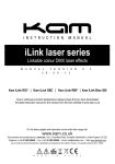
Powercan15W Low profile multicolour LED stage lighting M A N U A L V E R S I O N 1 . 0 2 0 - 1 0 - 1 4 For the latest instruction manual updates and information on the entire Kam range visit: www.kam.co.uk Kam products are manufactured by: Lamba plc, Unit 1, Southfields Road, Dunstable, Bedfordshire, United Kingdom LU6 3EJ Telephone: (+44) (0)1582 690600 • Fax: (+44) (0)1582 690400 • Email: [email protected] • Web: www.lambaplc.com If this product is ever no longer functional please take it to a recycling plant for environmentally friendly disposal. Due to continuous product development, specifications and appearance are subject to change. © Copyright Lamba plc. E&OE. Thank you for purchasing this Kam product, we are sure that it will serve you for many years to come. To optimise it’s performance, please read these instructions carefully to familiarise yourself with the basic operations of the unit. Please retain them for future reference.This unit has been tested at the factory before being shipped to you. To prevent or reduce the risk of electrical shock or fire, do not expose the unit to rain or moisture. To prevent a fire hazard, do not expose the unit to any naked flame sources. Unplug this apparatus during lightning storms or if it is unlikely to be used for long periods of time. When installing the unit, please ensure you leave enough space around the unit for ventilation. Slots and openings in the unit are provided for ventilation to ensure reliable operation of the product and to protect it from overheating. To prevent fire hazard, the openings should never be blocked or covered. The unit is powered by the mains, always handle the power cable by the plug. Never pull out the plug by pulling on the cable. Never touch the power cable when your hands are wet as this could cause an electric shock. Do not tie a knot in the cable. The power cable should be placed such that it is not likely to be stepped on. A damaged power cable can cause a fire or give you an electrical shock. Check the power cord periodicaly, if you ever find that it is damaged, replace it before using the unit again. Contact your retailer for a replacement. The voltage of the available power supply differs according to country or region. Be sure that the power supply voltage of the area where this unit is to be used meets the requirements of the unit. The lightning flash symbol inside a triangle is to alert the user to the presence high voltage within the unit’s enclosure that may be of sufficient power to constitute a risk of electrical shock to persons. Caution: to prevent the risk of electric shock, do not attempt to open the unit. No user-serviceable parts inside. Refer all servicing to qualified service personnel. The exclamation mark inside a triangle is intended to alert the user to the presence of important operating and maintenance instructions in the literature accompanying the appliance. Please read and pay attention to all laser safety warning sticker labels on the unit. Select the installation location of your unit carefully. Avoid placing it in direct sunlight or locations subject to vibration and excessive dust. Do not use the unit where there are extremes in temperature (below 41ºF / 5ºC or exceeding 95ºF / 35ºC). Unpacking and safety Please unpack your new product carefully. Your new product should reach you in perfect condition. Please check that no damage has occurred during transit. If any damage is found, do not operate your unit. Please contact the retailer you purchased it from immediately. If there is any damage to the mains cable do not use the device. Always disconnect the unit from the mains supply when carrying out any cleaning of the unit. Manufacturer declarations In compliance with the following requirements: RoHS Directive (2002/95/EU) and WEEE Directive (2002/96/EU). If this product is ever no longer functional please take it to a recycling plant for environmentally friendly disposal. CE declaration of conformity R&TTE Directive (1999/5/EU), EMC Directive (2004/108/EU), Low Voltage Directive (2006/95/EU). The declarations are available on application from [email protected] Before putting the devices into operation, please observe the respective country-specific regulations. Overhead rigging Important - the installation must be carried out by qualified service personal only. Improper installation can result in serious injuries and /or damage to property. Overhead rigging required extensive experience. Working load limits should be respected, certified installation materials should be used, the installed unit should be inspected regularly for safety. l Make sure the area below the installation place is free from unwanted persons during rigging, de-rigging and servicing. l Locate the unit in a well ventilated spot, far away from any flammable materials and/or liquids. The fixture must be fixed at least 50cm from surrounding walls l The device should be installed out of reach of people and outside of areas where persons may walk by or be seated. l Before rigging make sure that the installation area can hold minimum point load of 10 times the device`s weight. l The device should be well fixed; a free swinging mounting is dangerous. l Do not cover any ventilation opening as this may result in overheating Before first time use, the unit should be inspected for safety. Inspection the unit regularly every year. AC power The unit is supplied with a power plug appropriate to its voltage. Should any other connections be required they must be carried out with the following configuration: Cable (EU) Cable (US) Pin International Brown Black Live L Light blue White Neutral N Yellow/green Green Earth DMX-512 connection If you are using a standard DMX controller, you can connect the DMX output of the controller directly to the DMX input of the first unit in a DMX chain. If you wish to connect a DMX controller with other XLR outputs you will need to use adapter cables. DMX output 1 = Shield 2 = Signal (-) 3 = Signal (+) DMX input Connect the DMX output of the first unit in a DMX chain with the DMX input of the next unit in the chain. Always connect the the output of one unit with the input of the next unit until all units are connected. If you use a controller with 5 pin DMX connection you will need to use a 5 pin to 3 pin adapter. Caution at the unit, the DMX cable has to be terminated with a terminator. Solder a 120 Ohm resistor between Signal (-) and Signal (+) into a 3-pin XLR connector and plug this into the DMX output of the last unit in the chain. Features i r y DMX OUT POWER OUT q e FUNCTION SETTING w Menu MIC Enter DMX IN POWER IN t u i Number Feature Function 1 Function setting LED Displays the current operating mode. 2 Function buttons Menu buttons to control the operating mode of the laser. 3 Microphone Mic for Sound-to-Light operation. 4 DMX output 3 pin XLR connector for DMX512 output communication. 5 DMX input 3 pin XLR connector for DMX512 input communication. 6 Power supply output Mains supply output for linking power to other units. 7 Power supply input Attach the mains cable here. Built-in fuse. 8 Cooling vents Do not cover. Function setting Using the four function buttons on the rear of the unit you can set the operating mode of the Powercan. Press the Menu button to display the different functions (see table below for a description of the functions). Use the Up or Down arrow buttons to make your selection. When you have chosen your desired mode, press the Enter button to confirm the change. Menu display Addr CHNd Function DMX address setting. This is changed using the Up or Down arrow buttons (1-512). 3CH - press the Enter button to choose 3 channel DMX operation. 7CH - press the Enter button to choose 7 channel DMX operation. rEd - press the Enter button / 0-255 red dimmer. NAnu GrEE - press the Enter button / 0-255 green dimmer. bLUE - press the Enter button / 0-255 blue dimmer. SHOU SH1 - SH7. Built-in shows. COLO CO1 - CO7. Manual colour selection. SPEE Auto speed setting from 01-99. Auto Auto mode. Soun Sound-to-Light mode. Press the Enter button to choose the sensitivity of the microphone (S01-S10). Temp The LED output power will reduce when the unit’s temperature increases towards 50°C. Ve1.0 Software version Ve1.0 DMX operation DMX channel Value Function 3 channel 7 channel - CH1 0-255 Dimmer CH1 CH2 0-255 Red dimmer CH2 CH3 0-255 Green dimmer CH3 CH4 0-255 Blue dimmer - CH5 0-255 Strobe 0-10 Disabled - CH6 - CH7 11-240 Single effect built-in program in Auto mode 241-250 Built-in program in Sound-to-Light mode 251-255 Mixed effect built-in programs in Auto mode 0-255 Auto speed DMX address setting When controlling the unit (or units) with a DMX controller, each one must be set with a specific DMX address. You can choose to set all units with the same DMX address or you can set every unit with its own DMX address. If all units are set with the same DMX address all units will be synchronised and operate in the same way, you cannot control each unit separately. If you set each unit with a different DMX address, they will receive the DMX signal from their own DMX address. You will now be able to control each unit individually. The DMX address that you set for each unit must be determined by the number of channels. This unit has 3 or 7 channels, therefore if you choose the 3 channel mode, you should set the starting address of the first unit to 1, the second unit must then be set to 4 (3+1), the third unit must be set to 7 (3+4) and so on. If you choose the 7 channel mode, you should set the starting address of the first unit to 1, the second unit must then be set to 8 (7+1), the third unit must be set to 15 (7+8) and so on. Product specification Mains input Beam angle AC100~240V, 50/60Hz DMX512 Auto Sound-to-Light Master/Slave 25° Light source 5 x 3w RGB 3-in-1 LEDs Rated power 20w Protection rating IP20 Operating temperature 10~40° DMX512 connections 3 pins XLR male/female DMX512 channels 3/7 Dimensions (WxDxH) 214.4 x 100.3 x 211.68mm (inc bracket) Nett weight 0.8Kg Control modes