1
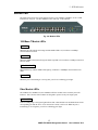
SNMP-FSH2602G
24+2 SNMP/Web Switch
24 x 10/100Base-TX Ports
Optional Gigabit/100BaseFX modules
SNMP, WEB, Telnet, Console Port Configurations
MIB II, Bridge MIB, RMON ons
User’s Manual
Trademarks
All rights reserved.
AirLive Logo is an registered trademarks of OvisLink Corp, Taiwan. Other product
names and company names are trademarks or registered trademarks of their respective
owners.
FCC Warning
This equipment has been tested and found to comply with the requirements for a Class A
digital device, pursuant to Part 15 of the FCC Rules. These requirements are designed for
reasonable protection against harmful interference when the equipment operating in a
commercial environment. This equipment can generate and radiate electromagnetic energy
and, if not installed and used in accordance with this guide, may cause significant
interference with radio communication. Operation of this equipment in a residential area is
likely to cause interference to household appliances, in which case the user will be required
to amend at his or her own expense.
CE Mark Warning
This is a Class A product. In a domestic environment, this product may cause radio
interference, in which case the user may be required to take adequate preventive measures.
Disclaimer
Contents in this manual are subject to changes without prior notice.
About this User’s Manual
This User’s Manual aims at helping users to know the key features of
SNMP-FSH2602G Management Switch and to install it in a Local Area
Network (LAN).
Chief Editor: Dr. Albert Yeh
Table of Contents
Table of Contents
TABLE OF CONTENTS ........................................................................................I
1
PRODUCT OVERVIEW ........................................................................1
Introduction....................................................................................................................... 1
Guide to the Chapters....................................................................................................... 1
Quick Setup ....................................................................................................................... 2
Power-On the switch....................................................................................................... 2
Ports and Indicators......................................................................................................... 2
Switch’s default IP address............................................................................................. 2
Console Port Information................................................................................................ 3
User’s Name and Password ............................................................................................ 3
LED Table....................................................................................................................... 3
2
INSTALLATION OF THE SWITCH.......................................................4
Installation Procedures..................................................................................................... 4
Unpack the Package.......................................................................................................... 5
Hardware Overview.......................................................................................................... 6
Front Panel ...................................................................................................................... 6
The Rear & Side Panel.................................................................................................... 6
Module Installation........................................................................................................... 7
Module Type................................................................................................................... 8
i
SNMP-FSH2602G Management Switch
User’s Manual V2.0
Table of Contents
Installation Site Preparation............................................................................................ 9
Rack Mounting.................................................................................................................. 9
Desktop Installation ........................................................................................................ 10
Cabling Requirements .................................................................................................... 11
For 100BASE-TX and 1000Base-T ports..................................................................... 11
Auto MDI/MDI-X function .......................................................................................... 11
Making your own UTP/STP cable................................................................................ 11
Connecting to Power....................................................................................................... 12
3
LED INDICATORS..............................................................................13
Comprehensive LEDs ..................................................................................................... 13
System LEDs.................................................................................................................... 13
FAN1 LED.................................................................................................................... 14
FAN2 LED.................................................................................................................... 14
Station Port LEDs for Port 1 ~ 24 ................................................................................. 14
Link/Act LED ............................................................................................................... 14
100M ............................................................................................................................. 14
Module LED .................................................................................................................... 15
1000Base-T Module LEDs ........................................................................................... 15
Fiber Module LEDs ...................................................................................................... 15
LED Table........................................................................................................................ 16
4
WEB MANAGEMENT...........................................................................17
In-Band and Out-of-Band Management....................................................................... 17
Setup your computer for Web management ................................................................ 17
The Concept of Subnet.................................................................................................. 17
ii
SNMP-FSH2602G Management Switch
User’s Manual V2.0
Table of Contents
Configure your computer’s IP ...................................................................................... 17
Remote Management ...................................................................................................... 19
Direct Connection to Internet........................................................................................ 19
Connect through Broadband Router ............................................................................. 20
Get into the Web Management...................................................................................... 20
Menu Bar ...................................................................................................................... 21
Top Switch Image. ........................................................................................................ 21
Port Status ....................................................................................................................... 21
All Port Status ............................................................................................................... 21
Single port status........................................................................................................... 22
Port Statistics................................................................................................................... 23
Administrator.................................................................................................................. 24
IP Address (Administrator menu) .......................................................................................... 24
Switch Setting (Administrator menu)..................................................................................... 25
Basic settings ................................................................................................................ 25
Module Info settings ..................................................................................................... 25
Advanced settings ......................................................................................................... 26
MAC Address Age-out Time........................................................................................ 26
Max bridge transit delay bound control .......................................................................... 26
Broadcast Storm Filter ................................................................................................ 26
Priority Queue Service settings (Administrator Menu -> Switch Settings->Advanced) ........................ 27
802.1p Priority ........................................................................................................ 27
QoS policy: High Priority Levels .............................................................................. 27
Collisions Retry Forever .......................................................................................... 27
802.1x Protocol ....................................................................................................... 27
Console Port Information (Administrator menu) ................................................................. 28
Port Controls (Administrator menu) ...................................................................................... 28
Ingress and Egress Control ............................................................................................ 29
Trunking (Administrator menu) ............................................................................................. 31
Aggregator setting......................................................................................................... 31
Aggregator Information ................................................................................................ 32
State Activity ................................................................................................................ 33
Filter Database (Administrator menu) ................................................................................... 34
IGMP Snooping ............................................................................................................ 34
Static MAC Address ..................................................................................................... 34
iii
SNMP-FSH2602G Management Switch
User’s Manual V2.0
Table of Contents
MAC filtering................................................................................................................ 35
VLAN configuration (Administrator menu) .......................................................................... 36
Port-based VLAN ......................................................................................................... 36
802.1Q Tag-based VLAN............................................................................................. 36
802.1v Protocol-based VLAN ...................................................................................... 37
GVRP (Generic Attribute Registration Protocol) ......................................................... 37
Configuring Port Based VLAN .................................................................................... 37
Configuring 802.1Q and 802.1v VLAN ....................................................................... 38
Spanning Tree (Administrator menu) .................................................................................... 41
Setting Spanning Tree................................................................................................... 41
Port Sniffer (Administrator menu) ......................................................................................... 43
SNMP/Trap Manager (Administrator menu) ....................................................................... 43
Security Manager (Administrator menu) .............................................................................. 44
Introduction to 802.1x Authentication Protocol .......................................................... 45
802.1x Configuration (Administrator menu) ......................................................................... 46
System Configuration ................................................................................................... 46
Per Port Configuration .................................................................................................. 47
Misc Configuration ....................................................................................................... 47
TFTP Update Firmware................................................................................................. 48
TFTP Restore Configuration......................................................................................... 48
TFTP Backup Configuration......................................................................................... 49
Reset System .................................................................................................................... 49
Reboot .............................................................................................................................. 49
5
TERMINAL MANAGEMENT ................................................................50
In-Band and Out-of-Band Management....................................................................... 50
Configure for Telnet management ................................................................................ 50
The Concept of Subnet.................................................................................................. 50
Configure your computer’s IP ...................................................................................... 50
Remote Management .................................................................................................... 52
Telnet to the switch....................................................................................................... 53
iv
SNMP-FSH2602G Management Switch
User’s Manual V2.0
Table of Contents
Console Port Management ............................................................................................. 54
Making RS-232 Cable Connection to the Host PC....................................................... 54
Using Windows HyperTerminal ................................................................................... 55
Run Windows HyperTerminal utility ........................................................................... 55
Main Menu ...................................................................................................................... 58
Hot Keys........................................................................................................................... 58
Switch Configuration...................................................................................................... 59
Port Configuration ........................................................................................................ 59
Trunk Configuration ...................................................................................................... 60
VLAN Configuration ...................................................................................................... 61
VLAN Configure .......................................................................................................... 62
Create a VLAN Group .................................................................................................. 63
Create 802.1Q VLAN ................................................................................................... 63
Edit / Delete a VLAN Group ........................................................................................ 64
Groups Sorted Mode ..................................................................................................... 65
Misc Configuration ......................................................................................................... 67
MAC Age Interval ........................................................................................................ 67
Broadcast Storm Filtering ............................................................................................. 68
Max bridge transmit delay bound ................................................................................. 68
Port Security.................................................................................................................. 69
Collision s Retry Forever .............................................................................................. 70
Administration Configuration ....................................................................................... 70
Change Username ......................................................................................................... 71
Change Password .......................................................................................................... 71
Device Information ....................................................................................................... 72
IP Configuration............................................................................................................ 72
Port Mirror Configuration ........................................................................................ 73
Priority Configuration.................................................................................................... 74
Port Static Priority......................................................................................................... 74
802.1p Priority Configuration....................................................................................... 75
MAC Address Configuration......................................................................................... 76
Static MAC Address ..................................................................................................... 76
Filtering MAC Address................................................................................................. 79
Protocol Related Configuration..................................................................................... 81
STP Spanning Tree Protocol........................................................................................ 82
SNMP............................................................................................................................ 84
Trap Managers .............................................................................................................. 87
v
SNMP-FSH2602G Management Switch
User’s Manual V2.0
Table of Contents
GVRP............................................................................................................................ 90
IGMP............................................................................................................................. 90
LACP (Link Aggregation Control Protocol) .............................................................. 91
802.1x Protocol ............................................................................................................. 94
Status and Counters........................................................................................................ 97
Port Status ..................................................................................................................... 97
Port Counters ................................................................................................................ 98
System Information....................................................................................................... 98
Reboot Switch.................................................................................................................. 99
Default........................................................................................................................... 99
Restart ........................................................................................................................... 99
TFTP Update Firmware............................................................................................... 100
TFTP Update Firmware .............................................................................................. 100
Restore Configure File................................................................................................ 101
Backup Configure File................................................................................................ 101
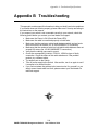
APPENDIX A PRODUCT SPECIFICATIONS ................................................103
APPENDIX B TROUBLESHOOTING.............................................................106
vi
SNMP-FSH2602G Management Switch
User’s Manual V2.0
Table of Contents
Figures
Fig. 2-1 Package Contents .............................................................................................. 5
Fig. 2-2 Front Panel ........................................................................................................ 6
Fig. 2-3 Rear & Side Panel ............................................................................................. 6
Fig. 2-4 Fastening the brackets on the switch................................................................. 9
Fig. 2-5 Attaching the Switch to a 19-inch rack ........................................................... 10
Fig. 2-6 Desktop installation......................................................................................... 10
Fig 2-9 Connecting the Switch to power outlet ............................................................ 12
Fig. 3-1 Front-panel LED indicators............................................................................ 13
Fig. 3-2 System LEDs.................................................................................................. 13
Fig. 3-3 Stantion Port LEDs......................................................................................... 14
Fig. 3-4 Module LEDs ................................................................................................. 15
Figure 4-1 Manual IP setting ........................................................................................ 18
Figure 4-2 Remote Management through direct Internet ............................................ 19
Figure 4-3 Remote Management through Broadband Router...................................... 20
Figure 4-2 Main Web Management Screen .................................................................. 21
Figure 4-3 All Port Status ............................................................................................ 22
Figure 4-4 Single Port Status ....................................................................................... 23
Figure 4-5 Port Stastics................................................................................................ 23
Figure 4-6 IP Configuration......................................................................................... 24
Figure 4-7 Switch Settings........................................................................................... 25
Figure 4-8 Module Info................................................................................................ 25
Figure 4-9 Advance Switch Settings............................................................................ 26
Figure 4-10 802.1p Priority Settings............................................................................ 27
Figure 4-11 Port Control Settings ................................................................................ 28
Figure 4-12 Trunking................................................................................................... 31
Figure 4-13 Trunking State Activity............................................................................ 33
Figure 4-14 IGMP Snooping ....................................................................................... 34
Figure 4-15 Static MAC address.................................................................................. 35
Figure 4-16 MAC filtering........................................................................................... 35
Figure 4-16 Enable VLAN configuration .................................................................... 36
Figre 4-17 Configure Port-Based VLAN..................................................................... 37
Figure 4-18 Configure 802.1Q/V VLAN.................................................................... 38
Figure 4-19 Set Spanning Tree .................................................................................... 42
Figure 4-20 Span Tree Port Parameter......................................................................... 42
Figre 4-21 Port Sniffer ................................................................................................. 43
Figure 5-1 Manual IP setting ........................................................................................ 51
Figure 5-2 Remote Management through direct Internet ............................................ 52
Figure 5-3 Remote Management through Broadband Router...................................... 53
Fig. 5-4 RS-232 Cable .................................................................................................. 54
Fig. 5-5 Console Port .................................................................................................... 55
Fig. 6-3 RS-232 Cable .................................................................................................. 55
vii
SNMP-FSH2602G Management Switch
User’s Manual V2.0
Table of Contents
Tables
Table 2-1 Module Specification Table ........................................................................... 8
Table 2-2 Cabling type for 10/100BASE-TX and 1000Base-T.................................... 11
Table 3-1 LED Table .................................................................................................... 16
Table 4-1 IGMP Snooping Messages .......................................................................... 34
Table 4-2 Span Tree Setting Parameters...................................................................... 42
viii
SNMP-FSH2602G Management Switch
User’s Manual V2.0
1 Product Overview
1
Product Overview
Introduction
The SNMP-FSH2602G features 24 Fast Ethernet ports with auto MDI/MDI-X function to eliminate
the need for cross-over cables. The single module slot can accept either single or dual-port modules
in 1000Base-T/-SX/-LX, 100Base-FX, or Dual-Mini-GBIC-Adapter specifications. All this power
is cooled by the dual fans with fan status LEDs on the front panel. Furthermore, the port's status
indicators are built adjacent to each port for fast viewing. All ports and status display are on the
front for easy access.
Phenomenal Power
The SNMP-FSH2602G is compliant with RFC1213 (RMON groups 1, 2, 3, 9), RFC1493 (Bridge
MIB), and RFC1643(Ether-Like MIB) SNMP standards. It features a full array of management
function including Spanning Tree, IGMP Snooping, LACP Trunking, 802.1Q Port-Based VLAN,
802.1p Priority, Access and Security control, GVRP Automatic VLAN Assignment, 802.1v
Protocol Based VLAN, RMON, and even the latest 802.1x authentication protocol.
SNMP for Everyone
All management functions can be configured through WEB browser, SNMP Management software,
Telnet, or the dedicated Console Port. The intuitive WEB interface is especially designed to allow
simple and speedy configurations even for the most advanced functions. Now, users can truly enjoy
the benefit of SNMP management without fear of being intimidated by its complexity. At any time,
users can click on the “help” icon for setup instruction inside the web management.
This user’s manual will help you to uncover most functions of the SNMP-FSH2602G with
step-by-step instructions presented by high quality illustrations. Thank you for choosing
OvisLink’s product.
Guide to the Chapters
Chapter 1:
Introduction and Quick Setup guide. All the essential information including IP Address and
Password information are in the Quick Setup section.
Chapter 2:
Detail installation instruction including module information and how to make Cat. 5 cable
Chapter 3: LED indicators
Chapter 4: Detail information on Web management Including how to setup remote
management.
Chapter 5: Detail instructions on Telnet and Console management.
1
SNMP-FSH2602G Management Switch
User’s Manual V2.0
1 Product Overview
Quick Setup
This section provides the essential information for experienced users to operate the switch
immediately. For detailed installation instruction, please see chapter 2 for more information.
Power-On the switch
The 24+2G Switch has a built-in power supply to operate with 90 ~ 260V AC, 50 ~ 60Hz power
source.
The AC power cord connector is located at the rear of the unit and the On/Off switch is next to
the connector.
After the Switch is powered on, it will perform “self-diagnostic” test. This process takes about
100 seconds to complete. During this process, the “DIAG” LED will blink and the Switch will
not response to any configuration program and all the connections to the Switch will not be
available. When the processed is completed, the “DIAG” LED will stay solid green.
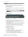
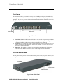
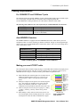
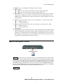
Ports and Indicators
DIAG LED
Console Port
Station Ports
Module Slot
The DIAG LED indicator will blink for 100 seconds during power-up to indicate the process of
diagnostic test. The switch will function only after the process is completed.
For management through smart console, a RS-232 cable should be used to connect the console
port with the computer’s COM port.
For management through Web browser or telnet, please make sure your PC is connected to any
of the 24 station ports.
To install a module, first make sure the switch’s power is off. Then unscrew the module slot
faceplate. Insert the module in place and turn the thumbscrews on the module to secure it.
There are 2 LEDs on the sides of each RJ-45 station port. The left LED indicates the
Link/Action Status. The right LED indicates whether the connection is in 100Mbps mode.
Switch’s default IP address
The Default IP configuration for the switch is:
IP Address:
192.168.223.100
Subnet Mask:
255.255.248.0
Gateway:
192.168.223.254
For Web and Telnet management, please set your computer’s IP address to the same subnet as
the switch (for example, IP: 192.168.223.101, Subnet Mask: 255.255.248.0).
After setting up the computer’s IP properly, please enter the switch’s IP address
“192.168.223.100 in Web browser or Telnet program to manage the switch.
If users can’t find the switch at the default IP address, please connect the switch to the console
port. Use the console port management to change the switch’s IP configuration.
2
SNMP-FSH2602G Management Switch
User’s Manual V2.0
1 Product Overview
Console Port Information
Please use a serial cable to connect between the console port of the switch and the COM port of
the computer.
Use a terminal program such as Window’s Hyperterminal
Open a new session and select the right COM port. Then enter the connection information as
followed:
Bits Rate per Second = 9600
Data Bits = 8
Parity = None
Stop Bit = 1
Flow Control = None
Please “enter” key to get into the smart console
Please note the smart console will not work during the 100second Power-On test.
User’s Name and Password
The Default User’s name and Password is as followed
User’s Name: admin
Password: 123
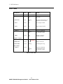
LED Table
LED indicator
Color
Status
Meaning
System LEDs
Power LED
● Green
ON
OFF
Power ON
Power OFF
DIAG LED
● Red
Blinking
ON
Performing Self-Diagnostic Test
Diagnostic Test is successful
FAN1
● RED
ON
Left Cooling Fan failed
FAN2
● RED
ON
Right Cooling Fan failed
● Green
ON
Blinking
OFF
Connection Established
Transmitting/Receiving
No connection is made
● Green
ON
OFF
100 Mbps Connection
10 Mbps Connection
● Orange
ON
Middle LED
● Green
ON
10Mbps Connectiont
Bottom LED
● Green
Blinking
Transmitting/Receiving
Station Port LEDs
Link/Act
100M
1000Base-T Module
Top LED
1000Mbps
100Mbps Connection
3
SNMP-FSH2602G Management Switch
User’s Manual V2.0
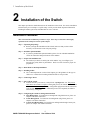
2 Installation of the Switch
2
Installation of the Switch
This chapter provides the detailed instructions for installation of the switch. For concise installation
instruction, the previous chapter’s “Quick Setup” section provides all the important information
including IP address, password, and LED table for user’s reference.
Installation Procedures
This section lists the installation procedures in steps. Each step’s instruction is thoroughly
explained in the subsequent sections of this chapter.
Step 1: Unpacking the package
Before you begin the installation of the Switch, make sure that you have all the
necessary accessories that come with your package
Step 2: Install the optional module
If you have purchased the optional module, please view the “Module Installation”
section for instruction and specifications of the modules.
Step 3: Prepare the installation site
The location you choose to install your switch and the way you configure your
network may greatly affect its performance. Please view this section for proper site
preparation
Step 4: Rack Mount or Desktop Installation
Step 5: Installing Cables
The “Cable Requirement” section of this chapter gives the guidance for the type of
cable to use. Instruction for making UTP/STP cables is also provided.
Step 6: Connecting to Power
Step 7: Power-On the switch.:
After the Switch is powered on, it will perform “self-diagnostic” test. This process
takes about 100 seconds to complete. During this process, the “DIAG” LED will blink
and the Switch will not response to any configuration program and all the connections
to the Switch will not be available. When the processed is completed, the “DIAG”
LED will stay solid green.
Step 8: Configuring the switch for management functions
Web Management: for instruction on management using Web browser, please see
Chapter 4 for further instruction.
Telnet Management: for instruction on management using Telnet, please see
Chapter 5 for further instruction.
Console Port Management: for instruction on management through console port,
please see Chapter 5 for further instruction.
4
SNMP-FSH2602G Management Switch
User’s Manual V2.0
2 Installation of the Switch
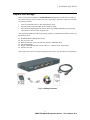
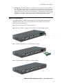
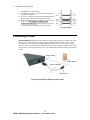
Unpack the Package
Before you begin the installation of SNMP-FSH2602G Management Switch, make sure that you
have all the necessary accessories that come with your package. Follow the steps below to unpack
your package contents:
1.
2.
3.
Clear out an adequate space to unpack the package carton.
Open the package carton and take out the contents carefully.
Put back all the shipping materials such as plastic bag, padding and linings into the package
carton and save them for future transport need.
After unpacking and taking out the entire package contents, you should check whether you have got
the following items:
⌧
⌧
⌧
⌧
⌧
⌧
SNMP-FSH2602G Management Switch
One AC power cord
Rack-mounting kit (screws and mounting brackets) and Rubber Pads
Quick Install Guide
Support CD-ROM (The PDF version of this User’s Manual can be found within)
One RS-232 Cable
If any of these above items is missing or damaged, please contact your local dealer for replacement.
Fig. 2-1 Package Contents
5
SNMP-FSH2602G Management Switch
User’s Manual V2.0
2 Installation of the Switch
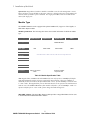
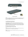
Hardware Overview
Front Panel
The front panel is where you can find the twenty-four 10/100Mbps station ports, the module slot,
console port, and the LED indicators. For the technical specifications of the ports, please refer to
Appendix A, Product Specifications for detailed information. For detailed explanation of the LED
lights, please refer to chapter 3 “LED Indicators”.
Station Ports
Power LED
DIAG LED
Console Port
Module Slot
Fig. 2-2 Front Panel
DIAG LED: The DIAG LED indicator will blink for 100 seconds during power-up to indicate
the process of diagnostic test. The switch will function only after the power-on diagnostic test
is completed. The DIAG LED will stay solid green after the test is completed.
Console Port: The console port is where you can connect the switch (via a RS-232 cable) to a
computer for smart console management. Please refer to chapter 5 “Console Port and Telnet
management” for more information.
Module Slot: The module slot is where you can install the optional modules for the switch.
Please refer to the “Module Installation” section of this chapter for more information.
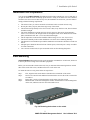
The Rear & Side Panel
The rear panel and side panel is where you can locate the power switch, AC power connector, and
cooling fans.
Cooling FAN
Power Switch
Power Connector
Fig. 2-3 Rear & Side Panel
6
SNMP-FSH2602G Management Switch
User’s Manual V2.0
2 Installation of the Switch
Cooling Fans : The SNMP-FSH2602G is equipped with 2 cooling fans located on the sides of
the switch. When facing front, the left cooling fan is designated as FAN 1 and the right cooling
fan is designated as FAN2. When a fan has failed, the fan status LED on the front panel will
light-up red to indicate a failure of the corresponding fan. Cooling fans are essential to keep the
switch from over-heating. Therefore, please make sure that the fan openings are not blocked
and there is at least 10cm (4 inch) of space on the sides to allow proper air circulation.
Module Installation
The SNMP-FSH2602G is equipped with a module slot for optional Gigabit, 100Base-FX, or
mini-GBIC-adapter modules. If you have purchased any of the modules, please follow the
instruction below for installation.
Step 1: Please make sure the power of the switch is off
Step 2: Please use a Philip’s screwdriver to remove the screws on the module faceplate
Step3: Insert the module into the slot until the module is in place.
Step 4: Turn the thumbscrews clockwise to secure the module
7
SNMP-FSH2602G Management Switch
User’s Manual V2.0
2 Installation of the Switch
Special Note: Regardless of whether a module is installed or not, the web management’s switch
image still shows a 2-port module on the panel. However, clicking on the ports of the module will
show the status of whether a port is installed. For single-port module, Port-25 will indicate the
status of the single port.
Module Type
The SNMP-FSH2602G can be equipped with optional 100Base-FX, Copper or Fiber Gigabit, or
Mini-GBIC adapter module.
Module Specification: The following table shows the essential information for different module
type:
Module Type
1000Base-T
Gigabit Copper
1000Base-SX
Gigabit Fiber
1000Base-LX
Gigabit Fiber
100Base-FX
Fiber
Cable Type
Cat. 5 UTP/STP
multi-mode Fiber
single mode or
multi-mode Fiber
multi-mode Fiber
10/100/1000 Mbps
1000 Mbps
1000 Mbps
100 Mbps
N/A
850nm Short
Wave Laser
1300nm Long
Wave Laser
850nm Short Wave
Laser
RJ-45
SC
SC
SC
Speed
Laser Type
Connector Type
Link Distance
(Full Duplex)
Cat 5 Cable
Note: MMF stands for Multi-mode Fiber, SMF stands for Single Mode Fiber
100 m
Unable to Use
Unable to Use
Unable to Use
62.5um MMF
Unable to Use
275 m
550 m
2 km
50um MMF
Unable to Use
550 m
550 m
2 km
10um SMF
Unable to Use
Unable to Use
5 km
Unable to Use
Unable to Use
Unable to Use
10 km or greater*
Unable to Use
9um SMF
Special Note
Recommend using
Category 5E cable or
better
Higher power
transceiver available
for special order
Table 2-1 Module Specification Table
Note: Gigabit Fiber (1000Base-SX and 1000Base-LX) can only operate in 1000Mbps full duplex
mode (the half duplex mode is no longer supported for most chipsets). There are commonly 2
standards for the switch to detect the operational mode. One is “forced 1000Mbps” mode, the other
is “Auto” mode. The Gigabit Fiber ports on both sides must be set to operate in the same detection
mode to work. The SNMP-FSH2602G’s fiber module is default to “forced 1000Mbps” mode. To
operate with fiber port in “auto” mode, please change the mode through web
Mini-GBIC Adapter: The mini-GBIC adapter module provides 2 empty Mini-GBIC slots for users
to install industrial standard Mini-GBIC modules.
8
SNMP-FSH2602G Management Switch
User’s Manual V2.0
2 Installation of the Switch
Installation Site Preparation
You can mount SNMP-FSH2602G Fast Ethernet Switch either on desktop or on a 19-inch rack. If
you plan to mount the switch on desktop, please choose a steady, level surface in a well-ventilated
area that is free from excessive dust. In any case, the installation site chosen for your switch has to
comply with the following requirements:
•
•
•
•
•
•
•
•
•
The surface where you want to mount the switch must be able to sustain at least 2.5kg.
Do not place heavy objects (more than 3kg) on top of the switch.
The location must preferably be free from excessive dust, away from heat vent, hot-air exhaust
and direct sunlight.
The switch should not be placed near large electric motors or other strong electromagnetic
sources. As a reference, the strength of the electromagnetic field on site should not exceed the
(RFC) standards for IEC 801-3, Level 2(3V/M) field strength.
The air temperature in the location should be within a range of 32 to 122 °F (0 to 55°C).
The relative humidity in the location should not exceed 95% non-condensing humidity.
The distance between the RJ-45 port and the standard network interface should not exceed 100
meters.
Adequate space should be allowed in front of all the ports, so that each port is easily accessible
for cable connections.
Leave at least 10cm(4 inch) of space around the switch to allow heating dissipation
Rack Mounting
SNMP-FSH2602G Management Switch can be mounted on a standard size 19-inch rack, which can
in turn be placed in a wiring closet with other equipments.
Before you can mount the switch on the rack, first you must attach the mounting brackets on both
sides of the switch with screws, and then mount it as a unit on the rack.
To mount the unit on a rack, please follow the steps below:
Step 1.
Step 2.
Step 3.
Step 4.
First, align the holes on the bracket with the holes on both side of the switch.
Insert screws into the holes and then fasten the bracket on one side of the switch with a
screwdriver.
Repeat Step 1 and 2 to fasten the bracket on the other side of the switch.
Mount the unit on the rack and align the notches on both brackets with mounting holes
on the rack, and then secure the unit with suitable screws.
Fig. 2-4 Fastening the brackets on the switch
9
SNMP-FSH2602G Management Switch
User’s Manual V2.0
2 Installation of the Switch
Fig. 2-5 Attaching the Switch to a 19-inch rack
Desktop Installation
SNMP-FSH2602G Management Switch has four rubber pads attached on each corner of its
underside. These pads serve as cushioning against vibration and prevent the switch from sliding off
its position. They also allow adequate ventilation space when you place the switch on top of another
device.
Fig. 2-6 Desktop installation
•
•
•
The location you choose to install your switch and the way you configure your network
may greatly affect its performance. Please see the previous section for “installation site”
preparation.
Do not place more than 3kg(6.6lbs) of weight on the top of the switch.
Leave at least 10cm (4 inch) of space around the switch to allow proper heating dissipation.
10
SNMP-FSH2602G Management Switch
User’s Manual V2.0
2 Installation of the Switch
Cabling Requirements
For 100BASE-TX and 1000Base-T ports
The 24 RJ-45 station ports and the 1000Base-T ports of the optional Gigabit-Copper module require
Cat. 5 twisted-pair UTP/STP cable for connection. When configuring within the
10/100/1000BASE-T cabling architecture, the cable distance should be within 100m.
The following table summarizes the cable requirement for 10/100/1000BASE-TX connection:
10BASE-T
100BASE-TX
1000BASE-T
100 ohm Category 3, 4, 5 UTP/STP cable
100 ohm Category 5 UTP/STP cable
100 ohm Category 5 UTP/STP cable or better
(CAT 5E recommended)
Auto MDI/MDI-X function
The SNMP-FSH2602G is equipped with Auto-MDI/MDI-X function, which allows you to use
straight-thru cable even when connecting to another switch/hub. Simply use the straight-through
cable for all types of 10/100/1000BASE-TX connections, either to a PC or to a networking device
such as other hub or switch.
Connection
Specification
Interface
Cable to Use
To an end station
To a hub/switch
Maximum Distance
10 /100Base-TX and 1000Base-T
Ports
RJ-45
Straight-through twisted-pair cable
Straight-through twisted-pair cable
100 meters
Table 2-2 Cabling type for 10/100BASE-TX and 1000Base-T
Making your own UTP/STP cable
The twisted-pair cable provided an eight-pin plug at each end that mate with the twisted-pair port on
the adapter and with a RJ-45 wall jack. If you are marking your own interface cables to use as
dedicated network wiring or as extension cables, please follow the guideline below:
Each UTP/STP cable contains eight wires in either 568A or
568B color scheme (please see Fig 2-7). The wires are
twisted in pairs to reduce cross talk and various signal
noises.
Each pairs composed of one positive wire and one negative
wire. The positive are marked by stripe color while the
negative are marked by solid color. A pair of wires is
composed of one stripe and one solid wire of the same color.
There are four pairs of wires, they are in group of {1 and 2},
{3 and 6},{4 and 5},{7 and 8}. Please see Fig 2-8 for
diagram.
When making a cable, make sure the correct pairs of wire
are twisted together before inserting into the jack. Incorrect
twisted pair will cause the cable to malfunction or signal
Fig 2-7 Twisted Pair
Color Scheme
11
SNMP-FSH2602G Management Switch
User’s Manual V2.0
2 Installation of the Switch
degradation over short distance.
A straight-thru cable have jacks on both end following
the same color scheme.
A cross-over cable have jacks on both end following the
opposite color scheme (one 568A and one 568B)
While 10/100Base-TX only use the first 2 pairs of wires
(1+2, 3+6). The 1000Base-T Gigabit Copper
connection uses all 4 pairs. Please make sure all 4 pairs
are twisted and insert into the jack in correct order.
Fig 2-8 Pair Wires
Connecting to Power
SNMP-FSH2602G management switch features a universal auto-select power supply unit, which
allows a power connection to a wide range of input voltages from 90 to 260VAC @ 50 ~ 60Hz.
To establish its power connection, simply plug the female end of the power cord into the power
connector on the rear of the switch and the male end of the power cord into a suitable power outlet.
Once you have correctly plugged in the power, you can then turn on the Power Switch to activate the
switch.
Power Switch
Power Outlet
Power Connector
Fig 2-9 Connecting the Switch to power outlet
12
SNMP-FSH2602G Management Switch
User’s Manual V2.0
3 LED Indicators
3
LED Indicators
Before connecting any network device to SNMP-FSH2602G Management Switch, you should take
a few minutes to look over this chapter and get familiar with the front panel LED indicators of your
Switch.
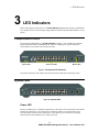
Comprehensive LEDs
The front-panel LED indicators of SNMP-FSH2602G comprise 3 sets of LEDs: System Status
LEDs, Station Port LEDs, and Module LEDs. Each set of LEDs gives specific information
concerning the system status or the station port status:
System LEDs
Station Port LEDs
Module LEDs
Fig. 3-1 Front-panel LED indicators
The specific function of each LED will be described in full details in the following sections:
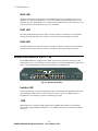
System LEDs
Fig. 3-2 System LEDs
Power LED
The Power LED will give a solid green light when you turn on the Switch, and will be off when the
Switch being turned off. You can simply check the Power LED to see if the Switch is being
activated. Before turning on the Switch, please verify that the power cord has been properly
connected to the Switch and the power outlet on the wall.
13
SNMP-FSH2602G Management Switch
User’s Manual V2.0
3 LED Indicators
DIAG LED
The DIAG LED indicator will blink for 100 seconds during power-up to indicate the process of
diagnostic test. During the Diagnostic test, the switch will not function and all the ports are not
available. Once the self-diagnostic test is completed, the DIAG LED will remain solid green. The
switch will function normally after the process is completed.
FAN1 LED
The FAN1 LED indicates the current status of the left cooling fan. When the fan is functioning
normally, the LED will remain off. If there is a fan failure, the LED will light up solid red.
FAN2 LED
The FAN2 LED indicates the current status of the right cooling fan. When the fan is functioning
normally, the LED will remain off. If there is a fan failure, the LED will light up solid red.
Station Port LEDs for Port 1 ~ 24
The SNMP-FSH2602G is equipped with 2 LEDs on the sides of each RJ-45 station port. This
design allows users to view the status of each port quickly. The left LED indicates the Link/Action
Status. The right LED indicates whether the connection is in 100Mbps mode
100M
Link/ACT
Fig. 3-3 Stantion Port LEDs
Link/Act LED
Link/Act LED giving a solid green light indicates that a data link has been established between the
corresponding port and the device. If no connection is made, it will be off. While the port is
transmitting or receiving data, you will see a blinking green light.
100M
100M LED giving a solid green light indicates that a 100Mbps data link has been established
between the corresponding port and the device. If a 10Mbps connection or no connection is made, it
will be off.
14
SNMP-FSH2602G Management Switch
User’s Manual V2.0
3 LED Indicators
Module LED
The Figure below shows the switch equipped with a 2-port 1000Base-T Modules. It has 3 LED
indicators for each port. The fiber Modules comes with only 1 LED indicator.
Fig. 3-4 Module LEDs
1000Base-T Module LEDs
TOP LED
When the top LED remain solid orange and the middle LED is off, it indicates a 100Mbps
connection has been made
Middle LED
When the middle LED remain solid green and the top LED is off, it indicates a 10Mbps connection
has been made.
TOP + Middle LED
When both the top and the middle LEDs light up, it indicates a 1000Mbps connection has been
made.
Bottom LED
While the port is transmitting or receiving data, you will see a blinking green light.
Fiber Module LEDs
The 100Base-FX, 1000Base-SX, and 1000Base-LX fiber modules comes with only one LED
indicator. This is because fiber modules are designed to operate in only one single speed.
Link/Act LED
Link/Act LED giving a solid green light indicates that a data link has been established between the
corresponding port and the device. If no connection is made, it will be off. While the port is
transmitting or receiving data, you will see a blinking green light.
15
SNMP-FSH2602G Management Switch
User’s Manual V2.0
3 LED Indicators
LED Table
LED indicator
Color
Status
Meaning
System LEDs
Power LED
● Green
ON
OFF
Power ON
Power OFF
DIAG LED
● Red
Blinking
ON
Performing Self-Diagnostic Test
Diagnostic Test is successful
FAN1
● RED
ON
Left Cooling Fan failed
FAN2
● RED
ON
Right Cooling Fan failed
● Green
ON
Blinking
OFF
Connection Established
Transmitting/Receiving
No connection is made
● Green
ON
OFF
100 Mbps Connection
10 Mbps Connection
● Orange
ON
Middle LED
● Green
ON
10Mbps Connectiont
Bottom LED
● Green
Blinking
Transmitting/Receiving
Fiber Modules
Link/Act
● Green
ON
Blinking
OFF
Connection Established
Transmitting/Receiving
No connection is made
Station Port LEDs
Link/Act
100M
1000Base-T Module
Top LED
1000Mbps
100Mbps Connection
Table 3-1 LED Table
16
SNMP-FSH2602G Management Switch
User’s Manual V2.0
4 Web Management
4
Web Management
The SNMP-FSH2602G switch supports in-band management through web browser. In this session,
you will learn how to access the switch’s powerful management functions through the web browser.
You will also learn how to manage the switch remotely through Internet. Please note that the current
firmware requires use of Internet Explorer for web configuration. For operation system that does
not support Internet Explorer, please go to chapter 5 for management through Telnet.
In-Band and Out-of-Band Management
In-Band and Out-of-Band managements are the two distinct methods for switch management.
In-Band management that includes Web, Telnet, and SNMP allows users to configure the switch
through the Ethernet network. By connecting the switch through a router or directly to Internet, user
can even manage the switch remotely.
Out-of-Band management means managing the switch outside of the switch’s Ethernet network.
Console Port management is the most common type of out-of-band management. Out-of-Band
management requires the switch to be physically attached to a computer through a RS-232, USB, or
Parallel port. It has the distinct security advantage and it can serve as a backup when In-Band
management function fails. For console port management, please see chapter 5 for more details.
Setup your computer for Web management
The Concept of Subnet
Under the TCP/IP environment, network devices must be on the same subnet in order to see each
other. This means before you can configure the switch through web browser, your must set your
computer to the same subnet as the switch. For two network devices to be on the same subnet, they
must have the following 2 criteria
:
Their IP address must be on the same subnet. For example, if one IP address is
192.168.0.1. The other’s IP address must be 192.168.0.x (x is any number between 2
and 254) for Class C subnet. To find out the IP address information for your computer.
Under WinNT/2000/XP, please open Command Line window and type “ipconfig”.
Under Win9x, please run “winipcfg”.
They must have the same subnet mask. For example, if one machine is
255.255.255.0. The other machine must also set to the same 255.255.255.0 mask.
Configure your computer’s IP
Before accessing the switch through web browse, please follow the instruction below to configure
your computer’s IP to the same subnet as the switch. If your switch’s IP has not been changed, it
should have the following factory default value:
17
SNMP-FSH2602G Management Switch
User’s Manual V2.0
4 Web Management
The switch’s Default IP
IP Address:
192.168.223.100
Subnet Mask:
255.255.248.0
Gateway:
192.168.223.254
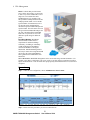
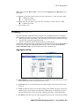
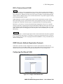
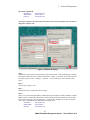
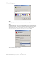
Now if your computer’s IP is not in the same subnet as the switch, please follow the steps below to
change the computer’s IP:
STEP 3
STEP 4
STEP 2
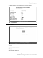
STEP 1
Figure 4-1 Manual IP setting
Step 1:
Double click on the network connection status icon on the task bar. This should bring up a window
showing the status of the current network connection. If there is no network status icon on the task
bar, please go to the “Start -> Settings -> Network -> Local Connection” of the task bar’s Start
menu.
Step 2:
Clock on the “property” icon.
Step 3:
Double click on the “Internet Protocol (TCP/IP)
Step 4:
Click on “Use the following IP address” button and enter the computer’s address manually. This IP
address must be on the same subnet as the switch but different from the switch’s IP. Please make
sure the IP is not used by other network device. If the switch’s IP address is of factory’s default
value. We recommend enter the following for computer’s IP:
IP Address:
192.168.223.101
Subnet Mask:
255.255.248.0
Gateway:
192.168.223.254
18
SNMP-FSH2602G Management Switch
User’s Manual V2.0
4 Web Management
Click “Okay” after finish entering the IP.
*Note: an alternative method is to change the switch’s IP to the same subnet as the computer.
Please use console-port management to change switch’s IP.
*Note2: If IP address of the switch is lost, please use console port management to find the switch’s
IP address.
*Note3: The SNMP-FSH2602G has DHCP client ability. This allows DHCP server (or router) to
assign IP automatically. However, we do not recommend turning on the DHCP client because the
DHCP server assign the IP randomly. The DHCP client should be used only when connecting
directly to Cable Modem (for remote management) whose service provider uses DHCP for IP
assignment.
Now, you will be able to access the switch by typing in the switch’s IP address on the web browser.
Remote Management
In this section, you will learn how to setup your computer and the router for remote web
management. Remote management allows MIS to manage a switch from outside of the switch’s IP
domain or from Internet. Depending on the type of Internet connection you have, there are two ways
to setup the switch to be available through Internet.
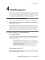
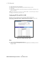
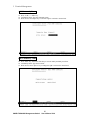
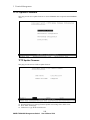
Direct Connection to Internet
Remote PC
Figure 4-2 Remote Management through direct Internet
If you have a fixed IP xDSL account or cable modem account, and there is no router in the network,
you can connect your switch directly to Internet via xDSL modem/Cable Modem. However, this
method is not recommended as the LAN will be directly exposed to the Internet.
Fixed IP: If your ISP has assigned you a fixed IP. Please go to the Switch’s IP configuration and
enter the IP address, Subnet Mask, and Gateway information offered by your ISP. If your ADSL
connection is PPPoE or PPTP type, you have to connect through a router for remote management.
Cable Modem: If your Cable service provider uses DHCP for IP assignment, please turn on the
DHCP function under IP configuration. Make sure there is no DHCP server in the network. Then
the Cable provider will assign the switch with a IP and Gateway. Go to the console port
management to find out what IP has been assigned to the switch.
When the configuration is finished, the Remote PC can access the switch by typing the switch’s IP
address on the web browser.
19
SNMP-FSH2602G Management Switch
User’s Manual V2.0
4 Web Management
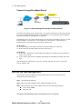
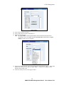
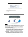
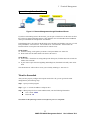
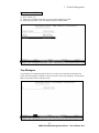
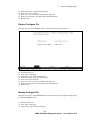
Connect through Broadband Router
201.100.1.5
192.168.0.254
Switch IP: 192.168.0.200
Remote PC
Figure 4-3 Remote Management through Broadband Router
If you have an IP sharing router in the network, you can open a virtual server on the router to allow
the switch to be managed through Internet. This method is more recommended as the broadband
router provide natural fire wall protector from hackers.
In the diagram above, the router has the WAN(given by the ISP) port IP address “201.100.1.5” and
LAN port address “192.168.0.254”. The switch’s IP is “192.168.0.200”. Please follow the
instruction below to setup the router and switch for remote access:
On the Switch
On the IP setting, set the gateway to Router’s LAN port address 192.168.0.254
Please make sure the subnet mask is the same as the router’s.
On the Router
Go to router’s Virtual Server setting and open the Web port (TCP Port 80) to the switch’s IP
address 192.168.0.200
If your router require enter the beginning and ending Port (from PortX to PortX), enter 80 for
both.
Now the Remote PC will be able to access your switch by entering “201.100.1.5” in the Web
browser’s address field.
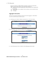
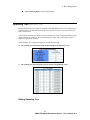
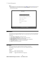
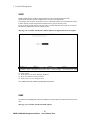
Get into the Web Management
After you have properly configure the computer and switch’s IP, you can get into the web
management by the following steps:
Step 1: Open the Internet Explorer
Step 2: Enter the switch’s IP address in the Address field and press enter.
Step 3: When prompt for User’s name and Password, enter the following information:
User’s Name: admin
Password: 123
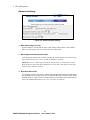
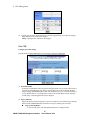
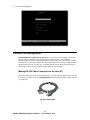
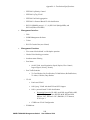
You should see the following welcome screen after the process is completed:
20
SNMP-FSH2602G Management Switch
User’s Manual V2.0
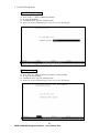
4 Web Management
Figure 4-2 Main Web Management Screen
Menu Bar
On the left side of the screen is the Menu bar where you and click to configure management
functions. Most configuration functions are under the “Administrator” menu. We will explain the
menu items in the remaining section of this chapter.
Top Switch Image.
The switch’s image on the upper portion of the screen gives the quick overview of the port
connection status. When a port is plugged in, the switch’s image will show a “plug” on the
corresponding port. Click on a port will show the quick port status. Please note that the switch’s
image shows a 2-port 1000Base-TX module even when there is no module installed. However,
clicking on the module port state will show whether the port is installed. If only 1-port module is
installed, Port-25 will show the status of the single module port.
Port Status
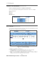
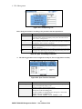
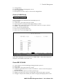
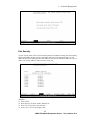
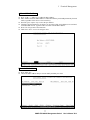
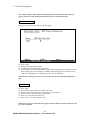
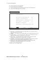
All Port Status
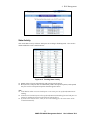
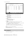
Click on “Port Status” of the left menu bar will bring up the general status for all the ports and
modules.
21
SNMP-FSH2602G Management Switch
User’s Manual V2.0
4 Web Management
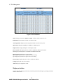
Figure 4-3 All Port Status
State: Display port statuses: disable or enable. “Unlink” will be treated as “off ”.
Link Status: Down means “No Link”, UP means “Link”.
Auto Negotiation: Display the auto negotiation mode: auto/force/nway-force.
Speed status: Display 1000Mbps or 100Mbps or 10Mbps speed
Duplex status: Display full-duplex or half-duplex mode.
Flow Control: Full: Display the flow control is enabled or disabled in full mode.
Half: Display the backpressure is enabled or disabled in half mode.
Rate Control: Display the rate control setting.
Ingr: Display the port effective ingress rate of user setting.
Egr: Display the port effective egress rate of user setting.
Port Security: Display the port security is enabled or disabled.
Config: Display the state of user setting.
Atual: Display the negotiation result.
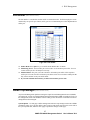
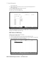
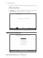
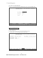
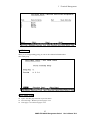
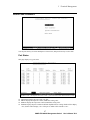
Single port status
User can also click the any port directly on the front panel of Home Page to get single port Status
which is shown below.
22
SNMP-FSH2602G Management Switch
User’s Manual V2.0
4 Web Management
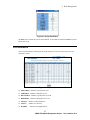
Figure 4-4 Single Port Status
The State shows whether the port has been installed. If no module is installed, the State of Port 25
and 26 will be off.
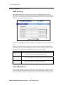
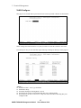
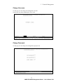
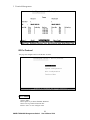
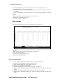
Port Statistics
Click on the Port Statistic will bring up the traffic statistics for all ports, click on the reset will
refresh the counter.
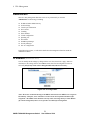
Figure 4-5 Port Stastics
TXGoodPKT – Number of good packets sent
TXBadPKT – Number of bad packets sent
RXGoodPKT – Number of good packets received
RXBadPKT – Number of bad packets received
TXAbort – Number of Aborted Packets
Collison
DropPKT
- Number of Collisions
- Number of Dropped Packets
23
SNMP-FSH2602G Management Switch
User’s Manual V2.0
4 Web Management
Administrator
There are many management functions can be set or performed if you click the
Administrator on Home Page, including:
IP address/Subnet Mask/Gateway
Switch settings
Console port information
Port controls
Trunking
Filter database
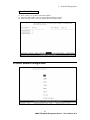
VLAN configuration
Spanning tree
Port Sniffer
SNMP/Trap Manager
Security Manager
802.1x Configuration
In the following sessions, we will talk in detail about the management functions under the
Administrator menu.
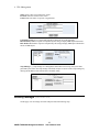
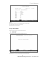
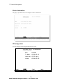
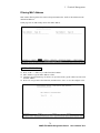
IP Address (Administrator menu)
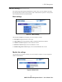
User can modify the IP Settings by filling with the new value, then clicks “apply” button to
confirm(save) his setting, then he must reboot switch, then new IP configuration Value are
activated. [note] If any of the value is changed in this field, reboot is necessary.
Figure 4-6 IP Configuration
Note3: We do not recommend turning on the DHCP client because the DHCP server assign the
IP randomly. Therefore, users will need to use the Console Port to find the IP address after
assignment. The DHCP client should be used only when connecting directly to Cable Modem
(for remote management) whose service provider uses DHCP for IP assignment.
24
SNMP-FSH2602G Management Switch
User’s Manual V2.0
4 Web Management
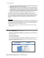
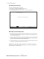
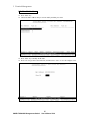
Switch Setting (Administrator menu)
The switch setting menu under the Administrator’s menu is where you can configure auto-aging
time, Broadcast Storm Control, 802.1p Priority, and to enable the 802.1x protocol. It also provide
basic information about the switch and module.
Basic settings
Figure 4-7 Switch Settings
All information in Basic are all read only, user can’t modify its contents.
Description: Display the name of device type.
MAC Address: The unique hardware address assigned by manufacturer (default)
Firmware Version: Display the switch’s firmware version.
Hardware Version: Display the switch’s Hardware version.
Default config value version: Display write to default EEPROM value version.
Module Info settings
All information in this field are read only, user can’t modify its contents, it is only to display the
module card information.
Figure 4-8 Module Info
25
SNMP-FSH2602G Management Switch
User’s Manual V2.0
4 Web Management
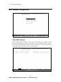
Advanced settings
Figure 4-9 Advance Switch Settings
MAC Address Age-out Time
Type the number of seconds that an inactive MAC address remains in the switch's address
table. The valid range is 300~765 seconds. Default is 300 seconds.
Max bridge transit delay bound control
Limit the packets queuing time in switch. If enable, the packets queued exceed will be drop.
These valid values are 1sec, 2 sec, 4 sec and off. Default is 1 seconds.
NOTE: Make sure of “Max bridge transit delay bound control” is enabled before enable
Delay Bound, because Enable Delay Bound must be work under “Max bridge transit delay
bound control is enabled” situation.
Broadcast Storm Filter
To configure broadcast storm control, enable it and set the upper threshold for individual ports.
The threshold is the percentage of the port's total bandwidth used by broadcast traffic. When
broadcast traffic for a port rises above the threshold you set, broadcast storm control becomes
active. The valid threshold value are 5%, 10%, 15%, 20%, 25% and off.
26
SNMP-FSH2602G Management Switch
User’s Manual V2.0
4 Web Management
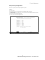
Priority Queue Service settings
(Administrator Menu -> Switch Settings->Advanced)
“The Priority Queue Service settings” is where you can configure the 802.1p Priority and QoS
settings. This is also the place where users can enable or disable the 802.1x authentication protocol.
You can find this settings in the Administrator->Switch Settings ->Advanced menu.
Figure 4-10 802.1p Priority Settings
802.1p Priority
First Come First Service: The sequence of packets sent is depending on arrive orders.
All High before Low: The high priority packets sent before low priority packets.
WRR: Weighted Round Robin. Select the preference given to packets in the switch's
high-priority queue. These options represent the number of high priority packets sent before
one low priority packet is sent. For example, 5 High:2 Low means that the switch sends 5
high-priority packets before sending 2 low- priority packets.
Enable Delay Bound: Limit the low priority packets queuing time in switch. Default Max
Delay Time is 255ms. If the low priority packet stays in switch exceed Max Delay Time, it
will be sent. The valid range is 1-255ms.
QoS policy: High Priority Levels
0~7 priority level can map to high or low queue.
Collisions Retry Forever
Disable – In half duplex, collision-retry maximum is 48 times and packet will be dropped if
collision still happen.
Enable – In half duplex, if happen collision will retry forever.
802.1x Protocol
Enable or disable 802.1x protocol.
27
SNMP-FSH2602G Management Switch
User’s Manual V2.0
4 Web Management
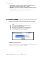
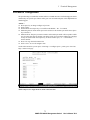
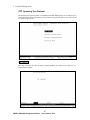
Console Port Information (Administrator menu)
Console is a standard UART interface to communicate with Serial Port.
User can use windows HyperTerminal program to link the switch. Connect To -> Configure:
Bits per seconds: 9600
Data bits: 8
Parity: none
Stop Bits: 1
Flow control: none
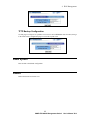
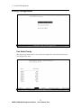
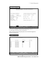
Port Controls (Administrator menu)
User may modify or change mode operation in this page. Please select a port under the “Port” field
and modify the port configuration in the subsequent field.
Figure 4-11 Port Control Settings
State: User can disable or enable this port.
Auto Negotiation: User can set auto negotiation mode is Auto, Nway (specify the
speed/duplex on this port and enable auto-negotiation), Force of per port.
Speed: User can set 100Mbps or 10Mbps speed on Port1~Port24; set 1000Mbps, 100Mbps or
10Mbps speed on Port25~Port26 (depend on module card mode).
28
SNMP-FSH2602G Management Switch
User’s Manual V2.0
4 Web Management
Duplex: User can set full-duplex or half-duplex mode of per port.
Flows control:
Full: User can set flow control function is enable or disable in full mode.
Half: User can set backpressure is enable or disable in half mode.
Rate Control: port1 ~ port 24, supports by-port ingress and egress rate control. For example,
assume port 1 is 10Mbps, users can set it’s effective egress rate at 1Mbps and ingress rate at
500Kbps. Device will perform flow control or backpressure to confine the ingress rate to meet
the specified rate.
Ingress: Type the port effective ingress rate. The valid range is 0 ~ 1000. The unit is 100K.
0: disable rate control.
1 ~ 1000: valid rate value
Egress: Type the port effective egress rate. The valid range is 0~1000. The unit is 100K.
0: disable rate control.
1 ~ 1000: valid rate value.
Port Priority:
Port Security: A port in security mode will be “locked” without permission of address learning.
Only the incoming packets with MAC already existing in the address table can be forwarded
normally. User can disable the port from learning any new MAC addresses, then use the static
MAC addresses screen to define a list of MAC addresses that can use the secure port. Enter the
settings, then click Apply button to change on this page.
Ingress and Egress Control
Function : Ingress and Egress control allow users to set the maximum speed for which a certain
port can operate. Ingress means the data rate coming into the port, Egress means the data rate going
out of the port. For example, if a port’s Ingress rate is set to 1000K and Egress rate is set to 100K.
That means the device connected to this port is limited to 1000Kbps receiving (downstream) speed
and 100Kbps sending speed (upstream). This type of control is called “bandwidth management.”
Separate bandwidth management for incoming and outgoing traffic is important because broadband
connection such as ADSL has different upstream and downstream speed.
Application
29
SNMP-FSH2602G Management Switch
User’s Manual V2.0
4 Web Management
Hotel: For hotels that provide internet
service to the guest rooms, it is necessary
to limit every room’s bandwidth so not a
single user can consume the entire
broadband speed. For example if the
hotel purchase a 8Mbps downstream and
1Mbps upstream ADSL service and the
typical number of simultaneous users is
10, then the switch should limit the
downstream speed to 800K and upstream
speed to 100K. This will ensure each user
will get sufficient bandwidth and prevent
one user consuming all the bandwidth.
Hotel can even provide services with
difference speed ratings for different
prices,.
Broadband Building: Broadband
connection has become almost a
requirement for modern buildings.
Commonly, a building or community
would rent high-speed broadband
connection and share it among the
households. Bandwidth management is
necessary to ensure not a single household
will occupy the entire bandwidth and
hence guarantee the bandwidth of each
household.
Server Protection: Bandwidth management can be used to discourage unwanted intruders. For
example, a port that is connected to a ftp server can be set to allow Egress at maximum speed but
Ingress at minimum rate. This will allow other people quickly download from the server, but restrict
on upload.
How to Setup
Step 1: Under the web configuration, choose Administrator->Port Control
Step 2: Please select the port where you want to control the rate
30
SNMP-FSH2602G Management Switch
User’s Manual V2.0
4 Web Management
Step 3: Under the field “Rate Control”, enter values in the Ingr(ingress) and Egr(egress) field
accordingly:
Ingress: Type the port effective ingress rate. The valid range is 0 ~ 1000. The unit is 100K.
0: disable rate control.
1 ~ 1000: valid rate value
Egress: Type the port effective egress rate. The valid range is 0~1000. The unit is 100K.
0: disable rate control.
1 ~ 1000: valid rate value.
Trunking (Administrator menu)
The Link Aggregation Control Protocol (LACP) provides a standardized means for exchanging
information between Partner Systems on a link to allow their Link Aggregation Control instances to:
1.
Reaching agreement on the identity of the Link Aggregation Group to which the link belongs
2.
Move the link to that Link Aggregation Group
3.
Enable its transmission and reception functions in an orderly manner.
In conclusion, Link aggregation lets you group up to eight consecutive ports into a single dedicated
connection. This feature can expand bandwidth to a device on the network. LACP operation
requires full-duplex mode, more detail information refers to IEEE 802.3ad
Aggregator setting
Figure 4-12 Trunking
System Priority: A value used to identify the active LACP. The switch with the lowest value
has the highest priority and is selected as the active LACP.
Group ID: There are seven trunk groups to provided configure. Choose the "group id" and
click "Get".
LACP: If enable, the group is LACP static trunking group. If disable, the group is local static
trunking group. All ports support LACP dynamic trunking group. If connecting to the device
that also supports LACP, the LACP dynamic trunking group will be created automatically.
Work ports: Allow max four ports can be aggregated at the same time. If LACP static trunking
31
SNMP-FSH2602G Management Switch
User’s Manual V2.0
4 Web Management
group, the exceed ports is standby and able to aggregate if work ports fail. If local static
trunking group, the number must be as same as the group member ports.
Select the ports to join the trunking group. Allow max four ports can be aggregated at
the same time.
If LACP enable, you can configure LACP Active/Passive status in each port on State
Activity page.
Click Apply.
Aggregator Information
Clicking on the Aggregator Information will show the state of the aggregator. Three different
screen can be shown to indicate the different status:
111...
If following screen is shown, it indicates no group is active. LACP is not working.
222...
If the following screen is shown, This indicate static Trunking groups has been made.
333...
If the following page is shown, it indicates LACP trunking group has been made.
32
SNMP-FSH2602G Management Switch
User’s Manual V2.0
4 Web Management
State Activity
Click on the State Activity will show which ports are working in Trunking mode. User can also
enable and disable LACP control from here.
Figure 4-13 Trunking State Activity
Active (select): The port automatically sends LACP protocol packets.
N/A (no select): The port does not automatically sends LACP protocol packets, and responds
only if it receives LACP protocol packets from the opposite device.
Note:
A link that has either two active LACP ports or one active port can perform dynamic LACP
trunking.
A link has two N/A LACP ports will not perform dynamic LACP trunking because both ports are
waiting for and LACP protocol packet from the opposite device.
If you are active LACP’s actor, when you are select trunking port, the active status will be
created automatically.
33
SNMP-FSH2602G Management Switch
User’s Manual V2.0
4 Web Management
Filter Database (Administrator menu)
IGMP Snooping
The SNMP-FSH2602G switch supports multicast IP, one can enable IGMP protocol on web
management’s switch setting advanced page, then display the IGMP snooping information in this
page, you can view difference multicast group, VID and member port in here, IP multicast addresses
range from 224.0.0.0 through 239.255.255.255.
Figure 4-14 IGMP Snooping
The Internet Group Management Protocol (IGMP) is an internal protocol of the Internet Protocol (IP)
suite.
IP manages multicast traffic by using switches, routers, and hosts that support IGMP. Enabling
IGMP allows the ports to detect IGMP queries and report packets and manage IP multicast traffic
through the switch. IGMP have three fundamental types of message as follows:
Message
Query
Description
A message sent from the queries (IGMP router or switch) asking for
a response from each host belonging multicast group.
Report
A message sent by a host to the queries to indicate that the host wants
to be or is a member of a given group indicated in the report message.
Leave Group
A message sent by a host to the queries to indicate that the host has
quit being a member of a specific multicast group.
Table 4-1 IGMP Snooping Messages
Static MAC Address
When you add a static MAC address, it remains in the switch's address table, regardless of whether
the device is physically connected to the switch. This saves the switch from having to re-learn a
device's MAC address when the disconnected or powered-off device is active on the network again.
34
SNMP-FSH2602G Management Switch
User’s Manual V2.0
4 Web Management
Figure 4-15 Static MAC address
At the main menu, click administrator Filter Database Static MAC Address.
In the MAC address box, enter the MAC address to and from which the port should
permanently forward traffic, regardless of the device’s network activity.
In the Port Number box, enter a port number.
If tag-based (IEEE 802.1Q) VLANs are set up on the switch, static addresses are associated
with individual VLANs. Type the VID (tag-based VLANs) to associate with the MAC address.
Click the Add.
MAC filtering
MAC address filtering allows the switch to drop unwanted traffic. Traffic is filtered based on the
destination addresses.
Figure 4-16 MAC filtering
35
SNMP-FSH2602G Management Switch
User’s Manual V2.0
4 Web Management
In the MAC Address box, enter the MAC address that wants to filter.
If tag-based (802.1Q) VLAN are set up on the switch, in the VLAN ID box, type the VID to
associate with the MAC address.
Click the Add.
Choose the MAC address that you want to delete and then click the Delete.
VLAN configuration (Administrator menu)
A Virtual LAN (VLAN) is a logical network grouping that limits the broadcast domain. It allows
you to isolate network traffic so only members of the VLAN receive traffic from the same VLAN
members. Basically, creating a VLAN from a switch is logically equivalent of reconnecting a group
of network devices to another Layer 2 switch. However, all the network devices are still plug into
the same switch physically.
The SNMP-FSH2602G switch supports port-based, 802.1Q (tagged-based) and protocol-base
VLAN in web management page. In the default configuration, VLAN support is disabled. You can
enable the VLAN function by choosing “Port Based VLAN” or “802.1Q” VLAN.
Figure 4-16 Enable VLAN configuration
Port-based VLAN
In port-based VLAN, users group member ports into different VLAN groups. Packets can only be
broadcast among only members of the same VLAN group. However, overlapping ports between
different VLAN groups can be used for device sharing purpose. If the port-based VLAN enabled,
the VLAN-tagging is ignored.
802.1Q Tag-based VLAN
Tagged-based VLAN is an IEEE 802.1Q specification standard. Therefore, it is possible to create a
VLAN across devices from different switch venders. IEEE 802.1Q VLAN uses a technique to insert
a “tag” into the Ethernet frames. Tag contains a VLAN Identifier (VID) that indicates the VLAN
numbers. Since each packet carries the VLAN ID of its traffic domain, the VLAN groups are no
longer confined by the ports.
36
SNMP-FSH2602G Management Switch
User’s Manual V2.0
4 Web Management
802.1v Protocol-based VLAN
Function:
802.1v not only allows VLAN assignment by Port, but also by the layer3 protocol for which the
packet runs. For example, we can define VLAN group 1 as any packet with VID value of 1 and that
runs on IP protocol. With 802.1Q TAG VLAN, the switch can support VLAN grouping through
multiple switches, adding the 802.v protocol VLAN classification, it is possible to group VLAN by
protocol through multiple switches
SNMP-FSH2602G switch will support protocol-based VLAN classification by means of both
built-in knowledge of layer 2 packet formats used by selected popular protocols, such as Novell IPX
and AppleTalk’s EtherTalk, and some degree of programmable protocol matching capability.
IEEE 802.1v provides user to classify the packet through untagged port. There are two possible
strategies of the 802.1v supporting: Port-based VLAN and Port-and-Protocol-based VLAN. We can
support both Port-based VLAN and Port-and-Protocol-based VLAN with our product. User set the
VID to mark the packet from untagged port. Then, the packet can be scheduled by the way of the
IEEE 802.1q.
Application:
Office and Enterprise: OvisLink support protocol base VLAN classification in IP, IPX, AppleTalk
protocols and many other formats. It is possible to setup VLAN groups based on layer-3 protocol,
so far example, users in the office using Apple Macintosh and IBM PC can be put automatically in
different VLAN groups.
GVRP (Generic Attribute Registration Protocol)
GVRP allows automatic VLAN configuration between the switch and nodes. If the switch is
connected to a device with GVRP enabled, you can send a GVRP request using the VID of a VLAN
defined on the switch, the switch will automatically add that device to the existing VLAN.
Configuring Port Based VLAN
Figre 4-17 Configure Port-Based VLAN
37
SNMP-FSH2602G Management Switch
User’s Manual V2.0
4 Web Management
Click Add to create a new VLAN group.
Enter the VLAN name, group ID and select the members for the new VLAN.
Click Apply.
If there are many groups that over the limit of one page, you can click the “Next Page” to view
other VLAN groups.
NOTE: If the trunk groups exist, you can see it (ex: TRK1, TRK2…) in select menu of ports, and you
can configure it is the member of the VLAN or not.
Configuring 802.1Q and 802.1v VLAN
This page, user can create Tag-based VLAN, and enable or disable GVRP protocol.
There are 4093 VLAN groups to provide configure. Enable 802.1Q VLAN, the all ports on the
switch belong to default VLAN, VID is 1. The default VLAN can’t be deleted.
Figure 4-18 Configure 802.1Q/V VLAN
Basic
Create a VLAN and add tagged member ports to it.
From the main menu, click Administrator VLAN configuration, click Add then you will see
the page as follow.
38
SNMP-FSH2602G Management Switch
User’s Manual V2.0
4 Web Management
Type a name for the new VLAN.
Type a VID (between 2-4094). The default is 1.
Choose the protocol type.
We support 802.1v with the implementation of Port-and-Protocol-based VLAN
classification. User can combine the field “Protocol Vlan” and the field of the port
number to form a new VLAN group.
From the Available ports box, select ports to add to the switch and click “Add >>”. If the trunk
groups exist, you can see it in here (ex: TRK1, TRK2…), and you can configure it is the
member of the VLAN or not.
Click Next. Then you can view the page as follow:
39
SNMP-FSH2602G Management Switch
User’s Manual V2.0
4 Web Management
Uses this page to set the outgoing frames are VLAN-Tagged frames or no. Then click Apply.
Tag: outgoing frames with VLAN-Tagged.
Untag: outgoing frames without VLAN-Tagged.
Port VID
Configure port VID settings
From the main Tag-based (IEEE 802.1Q) VLAN page, click Port VID Settings.
Port VID (PVID)
Set the port VLAN ID that will be assigned to untagged traffic on a given port. This feature is
useful for accommodating devices that you want to participate in the VLAN but that don’t
support tagging. SNMP-FSH2602G switch each port allows user to set one PVID, the range is
1~255, default PVID is 1. The PVID must as same as the VLAN ID that the port belong to
VLAN group, or the untagged traffic will be dropped.
Ingress Filtering
Ingress filtering lets frames belonging to a specific VLAN to be forwarded if the port belongs
to that VLAN. SNMP-FSH2602G switch have two ingress filtering rule as follows:
Ingress Filtering Rule 1:
A forward only packet with VID matching this port’s configured VID.
40
SNMP-FSH2602G Management Switch
User’s Manual V2.0
4 Web Management
Ingress Filtering Rule 2: Drop Untagged Frame.
Spanning Tree (Administrator menu)
The Spanning-Tree Protocol (STP) is a standardized method (IEEE 802.1D) for avoiding loops in
switched networks. Enable STP to ensure that only one path at a time is active between any two
nodes on the network.
You can enable Spanning-Tree Protocol on web management’s switch setting advanced item, select
enable Spanning-Tree protocol. We recommend that you enable STP on all switches ensures a
single active path on the network.
On the Spanning Tree configuration page are explained as following:
The spanning tree information about the Root Bridge in the following screen.
The spanning tree status about the switch is shown in the following screen.
Setting Spanning Tree
41
SNMP-FSH2602G Management Switch
User’s Manual V2.0
4 Web Management
Figure 4-19 Set Spanning Tree
Please change the Parameter according to the parameter table description below:
Parameter
Priority
Max Age
Hello Time
Forward Delay
time
Description
You can change priority value, A value used to identify the root bridge. The
bridge with lowest value has the highest priority and is selected as the root.
Enter a number 1 through 65535.
You can change Max Age value, The number of second bridge waits without
receiving Spanning-Tree Protocol configuration messages before attempting a
reconfiguration. Enter a number 6 through 40.
You can change Hello time value, the number of seconds among the
transmission of Spanning-Tree Protocol configuration messages. Enter a
number 1 through 10.
You can change forward delay time, The number of seconds a port waits before
changing from its Spanning-Tree Protocol learning and listening states to the
forwarding state. Enter a number 4 through 30.
Table 4-2 Span Tree Setting Parameters
The following parameter can be configured on each port, click set Apply button to modify
Figure 4-20 Span Tree Port Parameter
Parameter
Port Priority
Path Cost
Description
You can make it more or less likely to become the root port, the
rage is 0-255,default setting is 128
the lowest number has the highest priority.
Specifies the path cost of the port that switch uses to determine
which port are the forwarding ports
the lowest number is forwarding ports, the rage is 1-65535 and
default value base on IEEE802.1D
10Mb/s = 50-600 100Mb/s = 10-60 1000Mb/s = 3-10
42
SNMP-FSH2602G Management Switch
User’s Manual V2.0
4 Web Management
Port Sniffer (Administrator menu)
The Port Sniffer is a method for monitor traffic in switched networks. Traffic through ports can be
monitored by one specific port. That is, traffic goes in or out monitored ports will be duplicated into
sniffer port.
Figre 4-21 Port Sniffer
Sniffer Mode: Press Space key to set sniffer mode: Disable \Rx \Tx \Both.
Monitoring Port: It’ means sniffer port can be used to see all monitors port traffic. You can
connect sniffer port to LAN analyzer or netxray.
Monitored Port: The ports you want to monitor. All monitor port traffic will be copied to
sniffer port. You can select max 25 monitor ports in the switch. User can choose which port that
they want to monitor in only one sniffer mode.
If you want to disable the function, you must select monitor port to none.
SNMP/Trap Manager (Administrator menu)
Any Network Management platform running the simple Network Management Protocol (SNMP)
can manage the switch, provided the Management Information Base (MIB) is installed correctly on
the management station. The SNMP is a Protocol that governs the transfer of information between
management station and agent.
System Options: Use this page to define management stations as trap managers and to enter SNMP
community strings. User can also define a name, location, and contact person for the switch. Fill in
the system options data, and then click Apply to update the changes on this page.
43
SNMP-FSH2602G Management Switch
User’s Manual V2.0
4 Web Management
Name: Enter a name to be used for the switch.
Location: Enter the location of the switch.
Contact: Enter the name of a person or organization.
Community strings serve as passwords and can be entered as one of the following:
RO: Read only. Enables requests accompanied by this string to display MIB-object information.
RW: Read write. Enables requests accompanied by this string to display MIB-object information
and to set MIB objects.
Trap Manager :A trap manager is a management station that receives traps, the system alerts
generated by the switch. If no trap manager is defined, no traps are issued. Create a trap manager by
entering the IP address of the station and a community string.
Security Manager (Administrator menu)
On this page, user can change user name and password with following steps.
44
SNMP-FSH2602G Management Switch
User’s Manual V2.0
4 Web Management
User name: Type the new user name.
Password: Type the new password.
Reconfirm password: Retype the new password.
Click Apply.
Introduction to 802.1x Authentication Protocol
Function:
The 802.1x protocol allow authentication and authorization information to be embedded
inside the Ethernet frame through EAP(extended authentication protocol). This allows each
packet to be check for authentication without the need of opening tunnel through PPP protocol.
Because of this capability, 802.1x is particular suitable for wireless and broadband service
provider for authentication and accounting implementation. To setup a successful 802.1x
environment, 3 elements are needed:
Supplicant: The supplicant typically means a PC or mobile device that need the
wireless or broadband access. For WinXP, the 802.1x protocol is already supported in
the OS level. The network adapter’s driver should automatically add authentication
information into the Ethernet frame. On the diagram above, the PC on part 1 wants to
access Internet service through the switch, it will need to get authorized by the
authentication server on port 11 in order to gain access.
Authenticator: The authenticator is the device between the client and the Radius
server. It is typically an AP or switch. When a client needs to access certain service, the
authenticator will forward the request to the authentication server and wait for the
45
SNMP-FSH2602G Management Switch
User’s Manual V2.0
4 Web Management
authentication server to approve or deny service to the supplicant. Once authenticated,
supplicant can gain access through the authenticator.
Authentication Server: The 802.1x authentication server is typically the Radius server.
The Radius server will utilize a server port and an account port for authentication and
accounting purpose. These allow the server to keep track of the supplicant’s usage and
grant access based on the accounting information. The Radius server will analyze the
supplicant’s authentication information and decide what level of service the supplicant is
allowed. Then, it will pass this information to the authenticator for execution.
The SNMP-FSH2602G has full 802.1x authenticator capability. Therefore, even if your
Access Point is not 802.1x ready, the switch can still provide the function if the AP is
connected to the switch. The switch provides both server and accounting port to the Radius
server. It also allows users to define traffic for certain ports to be fully authorized or never
authorized. Its implementation is far more complete than most APs or switches in the
industry.
Application
Hotspot provider: Wireless ISP installs Access Point in airport, café, and many public areas.
They charge customer based on the usage. 802.1x gives service provider a feasible way for
authentication. With the SNMP-FSH2602G switch, the APs do not have to support 802.1x.
The authenticator function will be handled by the switch.
Hotel: Hotel can charge their customer base on usage of internet service through the
802.1x protocol.
802.1x Configuration (Administrator menu)
Before you can set up the 802.1x configuration, you have to enable the 802.1x control by going to
“Administrator -> Switch Settings -> Advanced” to enable the 802.1x protocol. The option is on
the bottom of the page.
System Configuration
802.1x makes use of the physical access characteristics of IEEE802 LAN infrastructures in order to
provide a means of authenticating and authorizing devices attached to a LAN port that has
point-to-point connection characteristics, and of preventing access to that port in cases in which the
authentication and authorization process fails.
46
SNMP-FSH2602G Management Switch
User’s Manual V2.0
4 Web Management
Radius Server IP Address: the IP address of the authentication server.
Server Port: The UDP port number used by the authentication server to authenticate.
Accounting Port: The UDP port number used by the authentication server to retrieve
accounting information.
Shared Key: A key shared between this switch and authentication server.
NAS, Identifier: A string used to identify this switch.
Per Port Configuration
In this page, you can select the specific port and configure the Authorization State.
Each port can select four kinds of Authorization State:
Fu:Force the specific port to be unauthorized.
Fa:Force the specific port to be authorized.
Au:The state of the specific port was determined by the outcome of the authentication.
No:The specific port didn't support 802.1x function.
Misc Configuration
In this page, you can change the default configuration for the 802.1x standard:
Quiet Period: Used to define periods of time during which it will not attempt to acquire a
supplicant(Default time is 60 seconds).
Tx Period: Used to determine when an EAPOL PDU is to be transmitted (Default value is 30
seconds).
Supplicant Timeout: Used to determine timeout conditions in the exchanges between the
supplicant and authentication server(Default value is 30 seconds).
47
SNMP-FSH2602G Management Switch
User’s Manual V2.0
4 Web Management
Server Timeout: Used to determine timeout conditions in the exchanges between the
authenticator and authentication server(Default value is 30 seconds).
ReAuthMax:Used to determine the number of reauthentication attempts that are permitted
before the specific port becomes unauthorized(Default value is 2 times).
Reauth Period: used to determine a nonzero number of seconds between periodic
reauthentication of the supplications(Default value is 3600 seconds).
TFTP Update Firmware
The following menu options provide some system control functions to allow a user to update
firmware and remote boot switch system:
Install TFTP program(such as Turbo98, or Cisco TFTP) on a computer connected to the
switch.
Copy updated firmware image. bin into TFTP server’s directory.
Find out what is the computer’s IP address.
In web management select administrator—TFTP update firmware.
Enter the computer IP address into the “TFPT Server IP Address” field
Download new image.bin file by pressing <update firmware>.
After update finished, press <reboot> to restart switch.
TFTP Restore Configuration
Use this page to set ftp server address. You can restore EEPROM value from here, but you must put
back image in ftp server, switch will download back flash image.
48
SNMP-FSH2602G Management Switch
User’s Manual V2.0
4 Web Management
TFTP Backup Configuration
Use this page to set tftp server ip address. You can save current EEPROM value from here, then go
to the TFTP restore configuration page to restore the eeprom value.
Reset System
Reset Switch to the default configuration
Reboot
Reboot the Switch in software reset
49
SNMP-FSH2602G Management Switch
User’s Manual V2.0
5 Terminal Management
5
Terminal Management
The SNMP-FSH2602G switch supports terminal management through Telnet or Console Port.
Console Port management allows out-of-band management and serve as a backup when Web/Telnet
management fails. For station that does not have Internet Explorer, users can use Telnet for in-band
management. You will also learn how to manage the switch remotely through Internet on telnet.
In-Band and Out-of-Band Management
In-Band and Out-of-Band managements are the two distinct methods for switch management.
In-Band management that includes Web, Telnet, and SNMP allows users to configure the switch
through the Ethernet network. By connecting the switch through a router or directly to Internet, user
can even manage the switch remotely.
Out-of-Band management means managing the switch outside of the switch’s Ethernet network.
Console Port management is the most common type of out-of-band management. Out-of-Band
management requires the switch to be physically attached to a computer through a RS-232, USB, or
Parallel port. It has the distinct security advantage and it can serve as a backup when In-Band
management function fails.
Configure for Telnet management
The Concept of Subnet
Under the TCP/IP environment, network devices must be on the same subnet in order to see each
other. This means before you can configure the switch through telnet, your must set your computer
to the same subnet as the switch. For two network devices to be on the same subnet, they must have
the following 2 criteria
:
Their IP address must be on the same subnet. For example, if one IP address is
192.168.0.1. The other’s IP address must be 192.168.0.x (x is any number between 2
and 254) for Class C subnet. To find out the IP address information for your computer.
Under WinNT/2000/XP, please open Command Line window and type “ipconfig”.
Under Win9x, please run “winipcfg”.
They must have the same subnet mask. For example, if one machine is
255.255.255.0. The other machine must also set to the same 255.255.255.0 mask.
Configure your computer’s IP
Before accessing the switch through telnet, please follow the instruction below to configure your
computer’s IP to the same subnet as the switch. If your switch’s IP has not been changed, it should
have the following factory default value:
50
SNMP-FSH2602G Management Switch
User’s Manual V2.0
5 Terminal Management
The switch’s Default IP
IP Address:
192.168.223.100
Subnet Mask:
255.255.248.0
Gateway:
192.168.223.254
Now if your computer’s IP is not in the same subnet as the switch, please follow the steps below to
change the computer’s IP:
STEP 3
STEP 4
STEP 2
STEP 1
Figure 5-1 Manual IP setting
Step 1:
Double click on the network connection status icon on the task bar. This should bring up a window
showing the status of the current network connection. If there is no network status icon on the task
bar, please go to the “Start -> Settings -> Network -> Local Connection” of the task bar’s Start
menu.
Step 2:
Clock on the “property” icon.
Step 3:
Double click on the “Internet Protocol (TCP/IP)
Step 4:
Click on “Use the following IP address” button and enter the computer’s address manually. This IP
address must be on the same subnet as the switch but different from the switch’s IP. Please make
sure the IP is not used by other network device. If the switch’s IP address is of factory’s default
value. We recommend enter the following for computer’s IP:
IP Address:
192.168.223.101
Subnet Mask:
255.255.248.0
Gateway:
192.168.223.254
51
SNMP-FSH2602G Management Switch
User’s Manual V2.0
5 Terminal Management
Click “Okay” after finish entering the IP.
*Note: an alternative method is to change the switch’s IP to the same subnet as the computer.
Please use console-port management to change switch’s IP.
*Note2: If IP address of the switch is lost, please use console port management to find the switch’s
IP address.
*Note3: The SNMP-FSH2602G has DHCP client ability. This allows DHCP server (or router) to
assign IP automatically. However, we do not recommend turning on the DHCP client because the
DHCP server assign the IP randomly. The DHCP client should be used only when connecting
directly to Cable Modem (for remote management) whose service provider uses DHCP for IP
assignment.
Now, you will be able to access the switch by typing in the switch’s IP address through telnet.
Remote Management
In this section, you will learn how to setup your computer and the router for remote telnet
management. Remote management allows MIS to manage a switch from outside of the switch’s IP
domain or from Internet. Depending on the type of Internet connection you have, there are two ways
to setup the switch to be available through Internet.
Direct Connection to Internet
Remote PC
Figure 5-2 Remote Management through direct Internet
If you have a fixed IP xDSL account or cable modem account, and there is no router in the network,
you can connect your switch directly to Internet via xDSL modem/Cable Modem. However, this
method is not recommended as the LAN will be directly exposed to the Internet.
Fixed IP: If your ISP has assigned you a fixed IP. Please go to the Switch’s IP configuration and
enter the IP address, Subnet Mask, and Gateway information offered by your ISP. If your ADSL
connection is PPPoE or PPTP type, you have to connect through a router for remote management.
Cable Modem: If your Cable service provider uses DHCP for IP assignment, please turn on the
DHCP function under IP configuration. Make sure there is no DHCP server in the network. Then
the Cable provider will assign the switch with a IP and Gateway. Go to the console port
management to find out what IP has been assigned to the switch.
When the configuration is finished, the Remote PC can access the switch by typing the switch’s IP
address on the Telnet.
52
SNMP-FSH2602G Management Switch
User’s Manual V2.0
5 Terminal Management
Connect through Broadband Router
201.100.1.5
192.168.0.254
Switch IP: 192.168.0.200
Remote PC
Figure 5-3 Remote Management through Broadband Router
If you have an IP sharing router in the network, you can open a virtual server on the router to allow
the switch to be managed through Internet. This method is more recommended as the broadband
router provide natural fire wall protector from hackers.
In the diagram above, the router has the WAN(given by the ISP) port IP address “201.100.1.5” and
LAN port address “192.168.0.254”. The switch’s IP is “192.168.0.200”. Please follow the
instruction below to setup the router and switch for remote access:
On the Switch
On the IP setting, set the gateway to Router’s LAN port address 192.168.0.254
Please make sure the subnet mask is the same as the router’s.
On the Router
Go to router’s Virtual Server setting and open the Telnet port (TCP Port 80) to the switch’s IP
address 192.168.0.200
If your router require enter the beginning and ending Port (from PortX to PortX), enter 80 for
both.
Now the Remote PC will be able to access your switch by telneting to “201.100.1.5”.
Telnet to the switch
After you have properly configure the computer and switch’s IP, you can get into the telnet
management by the following steps:
Step 1: Open your telnet program
Step 2: type “o <switch’s IP address> and press enter
Step 3: When prompt for User’s name and Password, enter the following information:
User’s Name: admin
Password: 123
You should see the following welcome screen after the process is completed:
53
SNMP-FSH2602G Management Switch
User’s Manual V2.0
5 Terminal Management
Console Port Management
SNMP-FSH2602G Gigabit Ethernet Switch offers you a secure way to configure your Switch
through a RS-232 cable that connects its console port and the host PC. Using Windows
HyperTerminal (on Windows 95/98/NT/2000/XP) or utilities such as Telix or Procomm (on DOS
environment), you can easily configure the Switch f. But before you can actually configure the smart
management functions by your host PC, you should establish a proper RS-232 cable connection
between the console port of your switch and the COM port of your host PC.
Making RS-232 Cable Connection to the Host PC
The way to make a RS-232 cable connection is simple. Just prepare a proper RS-232 cable and, with
it, connect the console port of your SNMP-FSH2602G and the COM port (either COM1or COM2)
of your host PC.
Fig. 5-4 RS-232 Cable
54
SNMP-FSH2602G Management Switch
User’s Manual V2.0
5 Terminal Management
Fig. 5-5 Console Port
Fig. 6-3 RS-232 Cable
Note:
After you have established a RS-232 cable connection between SNMP-FSH2602G and your host
PC, if your SNMP-FSH2602G or the host PC is not powered on, you should power them up
before you can configure smart console functions.
Using Windows HyperTerminal
After you have properly established a RS-232 cable connection between the console port of
SNMP-FSH2602G and the host PC. You can now begin configuring station ports for the smart
console functions. Generally, you can use Windows HyperTerminal (on Windows 95/98/2000) or
utilities such as Telix or Procomm (on DOS environment) to access the Switch and perform smart
configuration. In the following section, we will offer you a configuration example using Windows
HyperTerminal on Windows 95/98/2000 platform.
Run Windows HyperTerminal utility
Step 1:
After the RS-232 connection is properly made, you should then run Windows HyperTerminal by
accessing Start menu/Accessory/Communication/HyperTerminal.
Step 2:
The HyperTerminal window appears with a dialog box to prompt you to enter a name and choose an
icon for the connection.
55
SNMP-FSH2602G Management Switch
User’s Manual V2.0
5 Terminal Management
SNMP-FSH2602G
Step 3:
Ether any name you would like to have for this connection (in this example, we use
SNMP-FSH2602G as name for the connection) and choose an icon. Click OK.
Step 4:
The Connect to dialog box appear. Since the HyperTerminal connection is made through console
port instead of a phoneline, you need only to configure the Connect using: drop-down combo box
(that means the settings of the rest of the combo box or list boxes can simply be ignored).
Choose the COM port that your RS-232 is connected to (in this case, it is COM2).
SNMP-FSH2602G
After you select the COM port, click OK.
56
SNMP-FSH2602G Management Switch
User’s Manual V2.0
5 Terminal Management
Step 5:
The COM port properties dialog box (in this case, COM1 Properties dialog box) appears.
Configure the various port settings such as followings:
Bits per second: 9600
Data bits: 8
Parity: None
Stop bits: 1
Flow Control: None
Click OK.
Step 6:
Press <Enter> when the blank screen appears
57
SNMP-FSH2602G Management Switch
User’s Manual V2.0
5 Terminal Management
Step 7:
When prompted for User’s name and password. Enter “admin” as username and “123” as password.
After the host PC has successfully connected to SNMP-FSH2602G, you will see the Switch
Setup Main Menu appears.
Main Menu
Once getting into the terminal management main screen, the Telnet and Console Port management
will share the same configuration method. There are six items on the main screen of the terminal
management.
Switch Static Configuration: Configure the switch.
Protocol Related Configuration: Configure the protocol function.
Status and Counters: Show the status of the switch.
Reboot Switch: Restart the system or reset switch to default configuration.
TFTP Update Firmware: Use TFTP to download image.
Logout: Exit the menu line program.
Hot Keys
There are numerous hotkey sequences listed near the bottom of each menu.
These hotkeys can help you quickly access the various configuration functions
of your switch.
Functions:
• TAB
Move cursor to the next item
• BACKSPACE Move cursor to the prior item
• ENTER
Toggle selected item to next configuration
58
SNMP-FSH2602G Management Switch
User’s Manual V2.0
5 Terminal Management
Switch Configuration
<Control Key>
You can press the key of Tab or Backspace to choose item, and press Enter key to select item
The action menu line as follow provided in later configure page.
Actions->
<Quit>: Exit the page of port configuration and return to previous menu.
<Edit>: Configure all items. Finished configure press
Ctrl+A:
Back to action menu line.
<Save>: Save all configure value.
<Previous Page>: Return to previous page to configure.
<Next page>:
Go to the next page to configure it.
Port Configuration
This page can change every port status.
Press Space key to change configures of per item.
59
SNMP-FSH2602G Management Switch
User’s Manual V2.0
5 Terminal Management
InRate (100K/unit):
User can set input rate control, per unit is 100K. The valid range is 0~1000.
0: disable rate control.
1~1000: valid rate value.
OutRate (100K/unit):
User can set output rate control, per unit is 100K. The valid range is 0~1000.
0: disable rate control.
1~1000: valid rate value.
Enabled:
User can disable or enable this port control.
“Yes” that mean the port is enable.
“No” that mean the port is disable.
Auto:
User can set auto negotiation mode is “Auto”, “Nway_Force”, “Force” of per port.
Spd/Dpx:
User can set “100Mbps” or “10Mbps” speed on port 1~port 24,
set “1000Mbps”, “100Mbps” or “10Mbps” speed on port25~port26 (depend on module
card mode), and set “full-duplex” or “half-duplex” mode.
Flow Control:
Full: User can set full flow control function (pause) as enable or disable.
Half: User can set half flow control function (backpressure) as enable or disable.
NOTE:
Pressing <Save> only can save one page configuration.
If the static trunk groups exist, you can see it (ex: TRK1, TRK2…) after port 26, and you can
configure all of the items as above.
Trunk Configuration
This page can create max seven trunk groups. User can arbitrarily select up to four ports from port
1~port 26 to build a trunking group.
60
SNMP-FSH2602G Management Switch
User’s Manual V2.0
5 Terminal Management
Actions->
Select <Edit> on actions menu
Press space key to configure the member port of trunk group. Besides, you have to set “Static”
or “LACP” for the corresponding trunk group of TRK1~TRK7 item.
“Static” – the normal trunk.
“LACP” – this trunk group have link aggregation control protocol.
Press Ctrl+A to go back action menu line
Select <Save> to save all configure value.
If the item of TRK1~TRK7 is set “Disable”, it’s mean the trunk group is deleted.
All ports in the same static trunk group will be treated as single port. So when you setting
VLAN members and Port configuration they will be toggled on or off simultaneously.
NOTE: If VLAN group exist, all of the members of static trunk group must be in same VLAN
group.
VLAN Configuration
61
SNMP-FSH2602G Management Switch
User’s Manual V2.0
5 Terminal Management
VLAN Configure
This page can set VLAN mode to port-based VLAN or 802.1Q VLAN or disable VLAN function.
NOTE: Change the VLAN mode for every time, user have to restart the switch for valid value.
If set 802.1Q VLAN, you can set PVID, ingress filtering 1 and ingress filtering 2 in this page too.
Actions->
PVID (Port VID: 1~255): Type the PVID.
NonMember Drop:
It matches that Ingress Filtering Rule 1 on web.
Forwarding only packets with VID matching this port’s configured VID.
Press Space key to choose “forward” or “drop” the frame that VID not matching this port’s
configured VID.
62
SNMP-FSH2602G Management Switch
User’s Manual V2.0
5 Terminal Management
UnTagged Drop:
It matches that Ingress Filtering Rule 2 on web.
Drop untagged frame.
Press Space key to choose “drop” or “forward” the untagged frame.
Create a VLAN Group
Create Port-Based VLAN
Create a port-based VLAN and add member/nonmember ports to it.
Select <Edit>.
VLAN Name: Type a name for the new VLAN.
Grp ID: Type the VLAN group ID. The group ID rang is 1~4094.
Member: Press <Space> key to choose VLAN member. There are two types to selected:
Member:the port is member port.
No:the port is NOT member port.
Press Ctrl+A go back action menu line.
Select <Save> to save all configure value.
NOTE: If the trunk groups exist, you can see it (ex: TRK1, TRK2…) after port26, and you can
configure it is the member of the VLAN or not.
Create 802.1Q VLAN
Create an 802.1Q VLAN and add tagged /untagged member ports to it.
Select <Edit>.
VLAN Name: Type a name for the new VLAN.
VLAN ID: Type a VID (between 1~4094). The default is 1. There are 256 VLAN groups to
provided configure.
Protocol VLAN: Press Space key to choose protocols type.
Member: Press Space key to choose VLAN member. There are three types to selected:
UnTagged:this port is the member port of this VLAN group and outgoing frames are NO
63
SNMP-FSH2602G Management Switch
User’s Manual V2.0
5 Terminal Management
VLAN-Tagged frames.
Tagged:this port is the member port of this VLAN group and outgoing frames are
VLAN-Tagged frames.
NO:The port is NOT member of this VLAN group.
Press Ctrl+A go back action menu line.
Select <Save> to save all configure value.
NOTE: If the trunk groups exist, you can see it (ex: TRK1, TRK2…) after port 26, and you can
configure it is the member of the VLAN or not.
Edit / Delete a VLAN Group
In this page, user can edit or delete a VLAN group.
Press <Edit> or <Delete> item.
Choose the VLAN group that you want to edit or delete and then press enter.
User can modify the protocol VLAN item and the member ports are tagged or un-tagged and
remove some member ports from this VLAN group.
After edit VLAN, press <Save> key to save all configures value.
64
SNMP-FSH2602G Management Switch
User’s Manual V2.0
5 Terminal Management
NOTE:
When pressing <Enter> once will complete deletion on delete mode.
The VLAN Name and VLAN ID cannot modify.
The default VLAN can’t be deleted.
Groups Sorted Mode
In this page, user can select VLAN groups sorted mode:
sorted by name
sorted by VID.
The Edit/Delete a VLAN group page will display the result.
In the Edit/Delete a VLAN Group page, the result of sorted by name.
65
SNMP-FSH2602G Management Switch
User’s Manual V2.0
5 Terminal Management
In the Edit/Delete a VLAN Group page, the result of sorted by VID.
66
SNMP-FSH2602G Management Switch
User’s Manual V2.0
5 Terminal Management
Misc Configuration
MAC Age Interval
Type the number of seconds that an inactive MAC address remains in the switch’s address table.
The valid range is 300~765 seconds. Default is 300 seconds.
67
SNMP-FSH2602G Management Switch
User’s Manual V2.0
5 Terminal Management
Broadcast Storm Filtering
This page is configuring broadcast storm control.
Press <Edit> to configure the broadcast storm filter mode.
Press Space key to choose the threshold value.
The valid threshold value is 5%, 10%, 15%, 20%, 25% and NO. Default is 5%.
Max bridge transmit delay bound
Max bridge transmit delay bound: Limit the packets queuing time in switch. If enabled, the
packets queued exceed will be drop. Press Space key to set the time. Those valid values are 1sec,
2sec, 4sec and off. Default is off.
Low Queue Delay Bound: Limit the low priority packets queuing time in switch. If enabled, the
low priority packet stays in switch exceed Low Queue Max Delay Time, it will be sent. Press
Space key to enable or disable this function. Default is disable.
Low Queue Max Delay Time: To set the time that low priority packets queuing in switch. The
valid range is 1~255ms. Default Max Delay Time is 255ms.
NOTE: Make sure “Max bridge transit delay bound control” is enabled before enabling Low
Queue Delay Bound, because Low Queue Delay Bound must be work under “Max bridge transit
delay bound control” is enabled situation.
68
SNMP-FSH2602G Management Switch
User’s Manual V2.0
5 Terminal Management
Port Security
A port in security mode will be “locked” without permission of address learning. Only the incoming
packets with SMAC already existing in the address table can be forwarded normally. User can
disable the port from learning any new MAC addresses, then use the static MAC addresses screen to
define a list of MAC addresses that can use the secure port.
Actions->
Select <Edit>.
Press Space key to choose enable / disable item.
Press Ctrl+A to go back action menu line.
Select <Save> to save all configure value.
69
SNMP-FSH2602G Management Switch
User’s Manual V2.0
5 Terminal Management
You can press <Next Page> to configure port9 ~ port26, press <Previous Page> return to last
page.
Collision s Retry Forever
Collisions Retry Forever: Disable – In half duplex, if happen collision will retry 48 times and
then drop frame.
Enable – In half duplex, if happen collision will retry forever (Default).
Administration Configuration
70
SNMP-FSH2602G Management Switch
User’s Manual V2.0
5 Terminal Management
Change Username
Use this page; user can change web management user name.
Type the new user name, and then press <Save> item.
Change Password
Use this page; user can change web management login password.
71
SNMP-FSH2602G Management Switch
User’s Manual V2.0
5 Terminal Management
Device Information
This page is provided to the user to configure the device information.
IP Configuration
User can configure the IP setting and fill in the new value.
72
SNMP-FSH2602G Management Switch
User’s Manual V2.0
5 Terminal Management
Port Mirror Configuration
The port mirroring is a method for monitor traffic in switched networks. Traffic through ports can be
monitored by one specific port. That is traffic goes in or out monitored ports will be duplicated into
monitoring port.
Actions->
Press Space key to change configure of per item.
Select <Edit>.
Sniffer Mode: Press Space key to set sniffer mode Disable、Rx、Tx or Both.
Monitoring Port: It means sniffer port can be used to see all monitors port traffic. Press Space
key to choose it.
Monitored Port: The ports you want to monitor. All monitor port traffic will be copied to sniffer
port. You can select max 25 monitor ports in the switch. User can choose which port to monitor
in only one sniffer mode. Press Space key to choose member port, “V” – is the member, “—“ –
not the member.
Press Ctrl+A go back action menu line
Select <Save> to save all configure value.
On the action menu line you can press <Next Page> to configure port9 ~ port26, press <Previous
Page> return to last page.
NOTE: Only has one sniffer mode in switch at the same time.
73
SNMP-FSH2602G Management Switch
User’s Manual V2.0
5 Terminal Management
Priority Configuration
Port Static Priority
This static priority based on port, if you set the port is high priority, income frame from this port
always high priority frame.
74
SNMP-FSH2602G Management Switch
User’s Manual V2.0
5 Terminal Management
802.1p Priority Configuration
There are 0~7-priority level can map to high or low queue.
Actions->
Select <Edit>.
Press Space key to select the priority level mapping to high or low queue.
High/Low Queue Service Ration H:L: User can select the ratio of high priority packets and low
priority packets.
Press Ctrl+A go back action menu line.
Select <Save> to save all configure value.
75
SNMP-FSH2602G Management Switch
User’s Manual V2.0
5 Terminal Management
MAC Address Configuration
Static MAC Address
When you add a static MAC address, it remains in the switch's address table, regardless of whether
the device is physically connected to the switch. This saves the switch from having to re-learn a
device's MAC address when the disconnected or powered-off device is active on the network again.
In this page user can add / modify / delete a static MAC address.
76
SNMP-FSH2602G Management Switch
User’s Manual V2.0
5 Terminal Management
Add static MAC address
Press <Add> --> <Edit> key to add static MAC address.
MAC Address: Enter the MAC address to and from which the port should permanently forward
traffic, regardless of the device’s network activity.
Port num: press <Space> key to select the port number.
Vlan ID: If tag-based (802.1Q) VLAN are set up on the switch, static addresses are associated
with individual VLANs. Type the VID to associate with the MAC address.
Press Ctrl+A to go back action menu line.
Then select <Save> to save all configure value.
Edit static MAC address
Press <Edit> key.
Choose the MAC address that you want to modify and then press enter.
77
SNMP-FSH2602G Management Switch
User’s Manual V2.0
5 Terminal Management
Press <Edit> key to modify all the items.
Press Ctrl +A to go back action menu line, and then select <Save> to save all configure value.
Delete static MAC address
Press <Delete> key.
Choose the MAC address that you want to delete and then press enter.
Pressing <Enter> once will complete deletion on delete mode.
78
SNMP-FSH2602G Management Switch
User’s Manual V2.0
5 Terminal Management
Filtering MAC Address
MAC address filtering allows the switch to drop unwanted traffic. Traffic is filtered based on the
destination addresses.
In this page user can add /modify /delete filter MAC address.
Add filter MAC address
Press <Add> --> <Edit> key to add a filter MAC address.
MAC Address: Type the MAC address to filter.
Vlan ID: If tag-based (802.1Q) VLAN are set up on the switch, type the VID to associate with
the MAC address.
Press Ctrl+A to go back action menu line, and then select <Save> to save all configure value.
79
SNMP-FSH2602G Management Switch
User’s Manual V2.0
5 Terminal Management
Edit filter MAC address
Press <Edit> key.
Choose the MAC address that you want to modify and then press enter.
Press <Edit> key to modify all the items.
Press Ctrl+A to go back action menu line, and then select <Save> to save all configure value.
80
SNMP-FSH2602G Management Switch
User’s Manual V2.0
5 Terminal Management
Delete filter MAC address
Press <Delete> key to delete a filter MAC address.
Choose the MAC address that you want to delete and then press enter.
When pressing <Enter> once will complete deletion on delete mode.
Protocol Related Configuration
81
SNMP-FSH2602G Management Switch
User’s Manual V2.0
5 Terminal Management
STP Spanning Tree Protocol
The Spanning-Tree Protocol (STP) is a standardized method (IEEE 802.1D) for avoiding loops in
switched networks. When STP enabled, to ensure that only one path at a time is active between any
two nodes on the network.
STP Enable
This page is show the users how to enable or disable Spanning Tree function. Press Space key to
select enable or disable.
82
SNMP-FSH2602G Management Switch
User’s Manual V2.0
5 Terminal Management
STP System Configuration
You can view spanning tree information about the Root Bridge on the left.
On the right, user can set new value for STP parameter.
NOTE: All about the parameter description please see the sections Web configuration’s
explanation of Spanning Tree.
Perport Configuration
83
SNMP-FSH2602G Management Switch
User’s Manual V2.0
5 Terminal Management
PortState: Display spanning tree status about the switch for per port is forwarding or blocking.
Select <Edit>.
PathCost: Specifies the path cost of the port that switch uses to determine which port are the
forwarding ports.
Priority: This means priority port, you can make it more or less likely to become the root port.
Press Ctrl +A back to action menu line.
Select <Save> to save all configure value.
On the action menu line you can press <Next Page> to configure port9 ~ port26, press
<Previous Page> return to last page.
NOTE: All about the parameter description please see the sections Web configuration’s
explanation of Spanning Tree.
SNMP
Any Network Management running the simple Network Management Protocol (SNMP) can be
management the switch.
Use this page to define management stations as trap managers and to enter SNMP community
strings. User can also define a name, location, and contact person for the switch.
System Options
Press <Edit>.
System Name: Type a name to be used for the switch.
System Contact: Type the name of contact person or organization.
System Location: Type the location of the switch.
Press Ctrl+A go back action menu line.
Press <Save> to save the configure value.
84
SNMP-FSH2602G Management Switch
User’s Manual V2.0
5 Terminal Management
Community Strings
Use this page to Add/ Edit/ Delete SNMP community strings.
Community Name: The name of current strings.
Write Access: Enable the rights is read only or read-write.
Restricted: Read only, enables requests accompanied by this string to display MIB-object
information.
Unrestricted: Read write, enables requests accompanied by this string to display MIB-object
information and to set MIB objects.
85
SNMP-FSH2602G Management Switch
User’s Manual V2.0
5 Terminal Management
Add Community Name
Press <Add> --> <Edit> key.
Community Name: Type the community name.
Write Access: Press Space key to select the right is restricted or unrestricted.
Edit Community Name
Press <Edit> key, choose the item that you want to modify and then press Enter.
Community Name: Type the new name.
Write Access: Press <Space> key to change the right is restricted or unrestricted.
86
SNMP-FSH2602G Management Switch
User’s Manual V2.0
5 Terminal Management
Delete Community Name
Press <Delete> key.
Choose the community name that you want to delete and then press enter.
When pressing <Enter> once will complete deletion on delete mode.
Trap Managers
A trap manager is a management station that receives traps, the system alerts generated by the
switch. If no trap manager is defined, no traps are issued. Create a trap manager by entering the IP
address of the station and a community string.
87
SNMP-FSH2602G Management Switch
User’s Manual V2.0
5 Terminal Management
Add SNMP trap manager
Press <Add> --> <Edit> to add the trap manager.
IP: Type the IP address.
Community Name: Type the community name.
Press Ctrl +A go to actions line, press <Save> key to save all configure.
Edit trap managers
Press <Edit> key, and then choose the item that you want to modify.
IP: Type the new IP address
Community Name: Type the community name.
Press Ctrl +A go to actions line, press <Save> key to save all configure.
88
SNMP-FSH2602G Management Switch
User’s Manual V2.0
5 Terminal Management
Delete trap manager
Press <Delete> key.
Choose the trap manager that you want to delete and then press enter.
When pressing <Enter> once will complete deletion on delete mode.
89
SNMP-FSH2602G Management Switch
User’s Manual V2.0
5 Terminal Management
GVRP
GVRP (GARP [Generic Attribute Registration Protocol] VLAN Registration Protocol)
GVRP allows automatic VLAN configuration between the switch and nodes.
For example, if the switch is connected to a device with GVRP enabled, you can enable this setting
to allow dynamic VLAN configuration information to be processed by the switch.
If a device sends a GVRP request using the VID of a VLAN defined on the switch, the switch will
automatically add that device to the existing VLAN.
This page you can enable / disable the GVRP (GARP VLAN Registration Protocol) support.
Select <Edit>.
Press Space key to choose Enabled / Disabled.
Press Ctrl+A back to action menu line.
Select <Save> to save configure value.
Note: GVRP must also be enabled on participating network nodes.
IGMP
The Internet Group Management Protocol (IGMP) is an internal protocol of the Internet Protocol (IP)
suite.
This page you can enable / disable the IGMP support.
90
SNMP-FSH2602G Management Switch
User’s Manual V2.0
5 Terminal Management
Select <Edit>.
Press Space key to choose Enabled / Disabled.
Press Ctrl+A go back action menu line.
Select <Save> to save configure value.
LACP (Link Aggregation Control Protocol)
This page can configure and view all the LACP status.
91
SNMP-FSH2602G Management Switch
User’s Manual V2.0
5 Terminal Management
Note: All ports support LACP dynamic trunking group. If connecting to the device that also
supports LACP, the LACP dynamic trunking group will be created automatically.
Working Port Setting
This page can set the actually work ports in trunk group.
Select <Edit>.
Group: Display the trunk group ID.
LACP: Display the trunk group’s LACP status.
LACP Work Port Num: The max number of ports can be aggregated at the same time. If LACP
static trunking group, the exceed ports is standby and able to aggregate if work ports fail. If
local static trunking group, the number must be the same as group ports.
NOTE: Before set this page, you have to set trunk group on the page of Trunk Configuration
first.
State Activity
Press <Edit>.
System Name: Type a name to be used for the switch.
System Contact: Type the name of contact person or organization.
System Location: Type the location of the switch.
Press Ctrl+A go back action menu line.
Press <Save> to save the configure value.
NOTE: If user set LACP mode in the trunk group, all of the member ports of this trunk group will
set "Active" automatic.
92
SNMP-FSH2602G Management Switch
User’s Manual V2.0
5 Terminal Management
LACP Status
When you’re setting trunking group, you can see the relational information here.
Static trunk group
LACP trunk group
<Quit>: Exit this page and return to previous menu.
<Previous Page>: Return to previous page to view.
<Next page>: Go to the next page to view.
93
SNMP-FSH2602G Management Switch
User’s Manual V2.0
5 Terminal Management
802.1x Protocol
This page can configure and view all the 802.1x status.
802.1x Enable
1.Select <Edit>.
2.Press Space key to choose Enabled / Disabled.
3.Press Ctrl+A go back action menu line.
4.Select <Save> to save configure value.
94
SNMP-FSH2602G Management Switch
User’s Manual V2.0
5 Terminal Management
802.1x System Configuration
1.
2.
3.
4.
5.
6.
7.
Press <Edit>.
Radius Server IP Address: the IP address of the authentication server.
Shared Key: A key shared between this switch and authentication server.
NAS, Identifier: A string used to identify this switch.
Server Port: The UDP port number used by the authentication server to authenticate.
6.Accounting Port: The UDP port number used by the authentication server to retrieve
accounting information.
Press Ctrl+A go back action menu line.
Press <Save> to save configure value.
Note:
95
SNMP-FSH2602G Management Switch
User’s Manual V2.0
5 Terminal Management
Fu:Force the specific port to be unauthorized.
Fa:Force the specific port to be authorized.
Au:The state of the specific port was determined by the outcome of the authentication.
No:The specific port didn't support 802.1x function.
802.1x Misc Configuration
Quiet Period: Used to define periods of time during which it will not attempt to acquire a
supplicant(Default time is 60 seconds).
Tx Period: Used to determine when an EAPOL PDU is to be transmitted (Default value is 30
seconds).
Supplicant Timeout: Used to determine timeout conditions in the exchanges between the
supplicant and authentication server(Default value is 30 seconds).
Server Timeout: Used to determine timeout conditions in the exchanges between the
authenticator and authentication server(Default value is 30 seconds).
ReAuthMax:Used to determine the number of reauthentication attempts that are permitted
before the specific port becomes unauthorized(Default value is 2 times).
Reauth Period: used to determine a nonzero number of seconds between periodic
reauthentication of the supplications(Default value is 3600 seconds).
Press Ctrl+A go back action menu line.
Press <Save> to save configure value.
96
SNMP-FSH2602G Management Switch
User’s Manual V2.0
5 Terminal Management
Status and Counters
You can press the key of Tab or Backspace to choose item, and press Enter key to select item.
Port Status
This page display every port status
Link Status: Display the port is link or no link.
InRate: Display the input rate control (100K/unit) setting value.
OutRate: Display the output rate control (100K/unit) setting value.
Enabled: Display the port is enabled or disable depended on user setting. Enable will be display
“Yes”, disable will be display “No”. If the port is unlink will be treated as “No”.
97
SNMP-FSH2602G Management Switch
User’s Manual V2.0
5 Terminal Management
Auto: Display the port is link on which Nway mode: Auto , Nway_Force , Force.
Spd/Dpx: Display the port speed and duplex.
FlowCtrl: In auto / Nway force mode, display the flow control status is enable or not after
negotiation.
In force mode, display the flow control status is enable or disable depending on user setting.
Actions
<Quit>: Exit the page of port status, and return to previous menu.
<Previous Page>: Display previous page.
<Next page>: Display next page.
Port Counters
The following information provides a view of the current status of the unit.
Actions->
<Quit>: Exit the page of port status, and return to previous menu.
<Reset All>: Set all count to 0.
<Previous Page>: Display previous page.
<Next page>: Display next page.
System Information
MAC Address: The unique hardware address assigned by manufacturer.
Firmware Version: Display the switch’s firmware version.
ASIC Version: Display the switch’s Hardware version.
PCBA version: Display the board number.
Serial number: Display the serial number assigned by manufacturer.
Module 1 Type: Display the module 1 type :1000Tx or 100Fx ext. Depend on module card
mode.
Module 1 information: Display the information saved in eeprom of module1.
Module 2 Type: Display the module 2 type :1000Tx or 100Fx ext. Depend on module card
mode.
98
SNMP-FSH2602G Management Switch
User’s Manual V2.0
5 Terminal Management
Module 2 information: Display the information saved in eeprom of module2.
Reboot Switch
Default
Reset switch to default configuration.
Restart
Reboot the switch in software reset.
99
SNMP-FSH2602G Management Switch
User’s Manual V2.0
5 Terminal Management
TFTP Update Firmware
This page provide user to update firmware or restore EEPROM value or upload current EEPROM
value.
TFTP Update Firmware
This page provides user use TFTP to update firmware.
Start the TFTP server, and copy firmware update version image file to TFTP server.
Press <Edit> on this page.
TFTP Server: Type the IP of TFTP server.
100
SNMP-FSH2602G Management Switch
User’s Manual V2.0
5 Terminal Management
Remote File Name: Type the image file name.
Press Ctrl+A go to action line.
Press <Save> key, it will start to download the image file.
When save successfully, the image file download finished too.
Restart switch.
Restore Configure File
This page user can restore EEPROM value, save image file before, form TFTP server.
Start the TFTP server.
Press <Edit> on this page.
TFTP Server: Type the IP of TFTP server.
Remote File Name: Type the image file name.
Press Ctrl+A go to action line.
Press <Save> key, it will start to download the image file.
When save successfully, the image file download finished too.
Restart switch.
Backup Configure File
This page user can save current EEPROM value to image file. Then go to the update configure page
to restore the EEPROM value.
Start the TFTP server.
Press <Edit> on this page.
TFTP Server: Type the IP of TFTP server.
101
SNMP-FSH2602G Management Switch
User’s Manual V2.0
5 Terminal Management
Remote File Name: Type the image file name.
Press Ctrl+A go to action line.
Press <Save> key, it will start to upload the image file.
When save successfully, the image file upload finished too.
Restart switch.
102
SNMP-FSH2602G Management Switch
User’s Manual V2.0
Appendix A Product Specifications
SNMP-FSH2602G Management Switch
Appendix A Product Specifications
•
Hardware
o
24 x 10/100Base-TX Nway, auto-sensing ports
o
Auto MDI/MDI-X to eliminate needs for cross-over cabling
o
Single Module Slot for optional
1-port or 2-port 1000Base-T(copper), 1000Base-SX(Fiber),
1000Base-LX(Fiber) Gigabit modules
1-port or 2-port 100Base-FX Fiber Modules
2-slot Mini-GBIC module
o
RS-232 Console Port for out-of-band management
o
3M bit packet buffer and 1M bit control buffer
o
Up to 14K MAC entries and 4K VLAN entries
o
Dual fans for extra cooling
o
LEDs:
Power, Diag, FAN1, FAN2
Port LEDs (LINK/ACT on the left, 100M on the right) built adjacent
to the sides of each port
o
•
19" inch rack mountable
Standard Compliance
o
IEEE 802.3 10BaseT Ethernet
o
IEEE 802.3u 100BaseTX Fast Ethernet
o
IEEE 802.3ab 1000Base-T Gigabit Ethernet over Cat.5 cable
o
IEEE 802.3z 1000BaseSX/LX Fiber Gigabit Ethernet
o
IEEE 802.3x flow control
o
IEEE 802.1d Spanning Tree
103
SNMP-FSH2602G Management Switch
User’s Manual V2.0
Appendix A Production Specifications
•
•
o
IEEE 802.1p Priority Control
o
IEEE 802.1q Tag VLAN
o
IEEE 802.3ad Link Aggregation
o
IEEE 802.1v Protocol Based VLAN classification
o
RFC1213(RMON groups 1, 2, 3, 9), RFC1493 (Bridge MIB), and
RFC1643(Ether-Like MIB)
Management Interface
o
Web
o
SNMP Management Software
o
Telnet
o
RS-232 Console Port (out of band)
Management Functions
o
Flow control for both half- or full-duplex operation
o
Head-of-Line blocking prevention
o
broadcast storm filtering
o
Port Status
On/Off, Link, Auto Negotiation, Speed, Duplex, Flow Control,
Ingress/Egress, Priority, Security
o
Port Traffic Statistics
Tx Good Packets, Rx Good Packets, Tx Bad Packets, Rx Bad Packets,
Tx Abort, Collision, Drop Packets
o
VLAN
Port-based VLAN
802.1Q tag- VLAN with both IVL and SVL Support
802.1v protocol-based VLAN classification
Supporting Protocols: IP, ARP, AppleTalk, AppleTalk AARP,
Novell IPX, Banyan Vines, DECnet MOP, DECnet DPR,
DECnet, LAT, DECnet LAVC, IBM SNA, X.75 Internet,
X.25 Layer 3
GVRP Auto VLAN Configuration
o
IP Multicast
104
SNMP-FSH2602G Management Switch
User’s Manual V2.0
Appendix A Product Specifications
o
IGMP
o
Support 802.1p 2-level priority queuing
o
Port-Trunking
flexible load distribution control and fail-over functions
Provide 7 trunk groups of up to 4 member ports within 26 ports
LACP Trunking
o
Ingress port security mode
o
RMON group 1,2,3,9
o
Auto Aging Control
o
Port Sniffer Function
o
MAC Address Control
Static MAC Address list to speed up MAC Address learning
Filter MAC Address List to drop traffic from certain stations
•
•
o
SNMP Trap Manager
o
Security Manager
o
Firmware update through TFTP or Xmodem
Power
o
Built-in Power Supply
o
Input: 90-260VAC, 50/60Hz
o
Consumption: 36 Watts max.
Dimension
440mm (W) X 184mm (D) X 44mm (H)
o
•
Weight
o
•
2 KG
Regulation
o
FCC Part 15 Class A
o
CE mark, Class A
105
SNMP-FSH2602G Management Switch
User’s Manual V2.0
Appendix A Production Specifications
Appendix B Troubleshooting
This appendix contains specific information to help you identify and solve problems.
If your switch does not function properly, please make sure it is set up according to
the instructions on the manual.
If you suspect your switch is not connected correctly to your network, check the
following points before you contact your local dealer for support.
•
•
•
•
•
•
•
•
•
Make sure the Power is ON (Check the Power LED).
Make sure the cable is connected properly on both ends.
Make sure that the maximum cable length between switch and end node
does not exceed 100 meters (for 10/100/1000BASE-TX connection).
Make sure that the maximum switch-to-hub/switch cable distance does not
exceed 100 meters (for 10/100/1000BASE-TX connection).
Verify that the cabling type used is correct.
Check the corresponding Link/Act, FDX/Col, 100M for signs of faulty
connection. Check the status of the cable attachment. If the problem
persists, try a different cable.
Try another port on the Switch.
Turn off power supply to the Switch. After a while, turn it on again to see if
it resumes to its normal function.
If you find out where the problem is but cannot solve it by yourself, or you
simply cannot locate what is at fault, please contact your local dealer for
technical support.
106
SNMP-FSH2602G Management Switch
User’s Manual V2.0